Connected Communities Infrastructure - General Solution Design Guide
Bias-Free Language
The documentation set for this product strives to use bias-free language. For the purposes of this documentation set, bias-free is defined as language that does not imply discrimination based on age, disability, gender, racial identity, ethnic identity, sexual orientation, socioeconomic status, and intersectionality. Exceptions may be present in the documentation due to language that is hardcoded in the user interfaces of the product software, language used based on RFP documentation, or language that is used by a referenced third-party product. Learn more about how Cisco is using Inclusive Language.
- Updated:
- November 8, 2021
Chapter: Connected Communities Infrastructure - General Solution Design Guide
- Scope of CCI Release 2.1
- References
- Document Organization
- Solution Overview
- Solution Architecture
- Solution Components
- CCI Switched Ethernet Access Network (PoPs)
- CCI Remote Point-of-Presence Design
- Ultra Reliable Wireless Backhaul
- CCI Wi-Fi Access Network
- CCI Wireless IoT Devices Networks
- Shared Network Services
- Conclusions
- Acronyms and Initialisms
Connected Communities Infrastructure General Solution Design Guide
Modernizing the technology landscape of our cities, communities, and roadways is critical. Efforts toward digital transformation will form the basis for future sustainability, economic strength, operational efficiency, improved livability, public safety, and general appeal for new investment and talent. These efforts can be complex and challenging. What we need is a different approach to address the growing number of connected services, systems, devices, and their volumes of data. Overwhelming options for connecting new technologies make decision-making more difficult and present risks that often seem greater than the reward. This approach will require a strategic and unified consideration of the broad needs across organizational goals and the evolving nature of the underlying technology solutions.
Typically, multiple connectivity solutions are traditionally created as separate and isolated networks. This leads to duplication of infrastructure and effort and cost, inefficient management practices, and less assurance for security and resiliency. Traditional networking also commonly manages on a per-device basis, which takes time, creates unnecessary complexities, and heightens exposure to costly human errors.
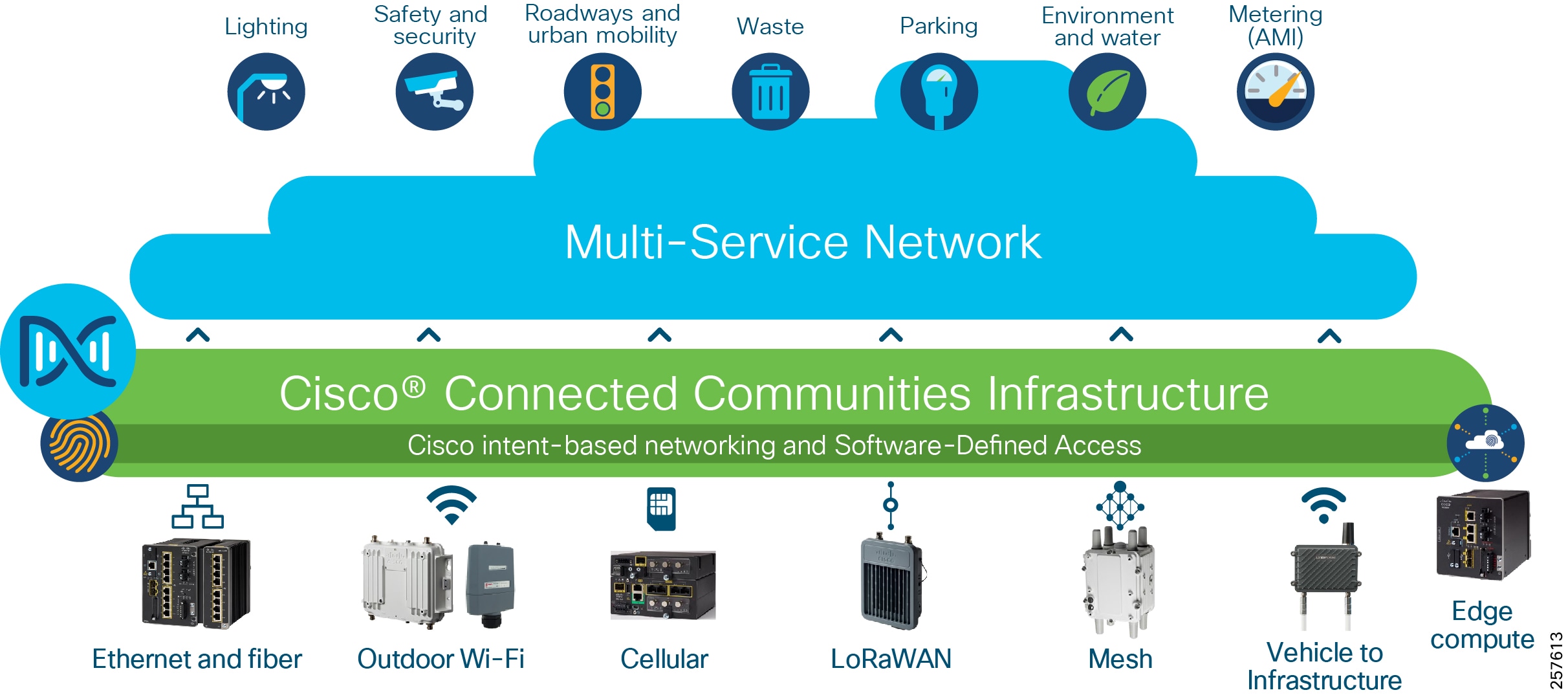
With Cisco Connected Communities Infrastructure (CCI), you can create a single, secure communications network to support all your needs that is simpler to deploy, manage and secure. Based on the market-defining Cisco Digital Network Architecture (Cisco DNA) and Intent-based Networking capabilities, this solution provides:
- A single, modular network with wired (fiber, Ethernet), wireless (Wi-Fi, cellular, and V2X) and Internet of Things (IoT) communications (LoRaWAN and Wi-SUN mesh) connectivity options for unmatched deployment flexibility
- Cisco Software-Defined Access (SD-Access) to virtually segment and secure your network across departments and services, each with its own policies, control, and management as needed
- Cisco DNA Center for network automation with unified management of communications policy and security that significantly lowers operational costs; Cisco DNA Center also provides assistance in security compliance, which is becoming a significant challenge for our customers to prove
- Highly reliable outdoor and ruggedized networking equipment with simplified zero-touch in-street and roadway deployment options
For additional overview materials, presentations, blogs and links to other higher-level information on Cisco’s Connected Communities Infrastructure solution please see: http://cisco.com/go/cci
Scope of CCI Release 2.1
This Design Guide provides network architecture and design guidance for the planning and subsequent implementation of a Cisco Connected Communities Infrastructure solution. In addition to this Design Guide, there are Connected Communities Infrastructure Cities Solution Design Guide, Connected Communities Infrastructure Roadways Solution Design Guide, Connected Communities Infrastructure Rail Solution Design Guide is and also a Connected Communities Infrastructure Implementation Guide that provides more specific implementation and configuration guidance and examples also exists.
For Release 2.1 of the CCI CVD, the horizontal scope covers all the access technologies listed in Cisco Connected Communities Infrastructure.
This Release 2.1 supersedes and replaces the CCI Release 2.0 Design Guide.
New capabilities in CCI Release 2.1
- Cisco Ultra Reliable Wireless Backhaul (CURWB) for CCI backhaul and wireless access networks
- Enhanced Ethernet Access Ring & Provisioning
–![]() IE-3300 10G Access Ring in CCI PoPs
IE-3300 10G Access Ring in CCI PoPs
–![]() Daisy Chaining Automation of Extended and Policy Extended Nodes using Cisco DNA Center
Daisy Chaining Automation of Extended and Policy Extended Nodes using Cisco DNA Center
–![]() REP Ring Automation using Cisco DNA Center
REP Ring Automation using Cisco DNA Center
–![]() CyberVision Sensor deployment on IE-3400, IE-3300 10G and IR-1101 Platform
CyberVision Sensor deployment on IE-3400, IE-3300 10G and IR-1101 Platform
–![]() OT Device and Protocols (DNP3 and MODBUS) Flow Detection using Cisco Cyber Vision Center
OT Device and Protocols (DNP3 and MODBUS) Flow Detection using Cisco Cyber Vision Center
- Enhanced End-to-End QoS design on IE3400 and IE3300 10G
- Enhanced Remote Point-of-Presence (RPoP) Management design
–![]() IR-1800 as RPoP gateway with multi-service and macro-segmentation at RPoP
IR-1800 as RPoP gateway with multi-service and macro-segmentation at RPoP
–![]() RPoP Management Design using Cisco DNA Center and Cisco IoT Operations Dashboard (IoTOD)
RPoP Management Design using Cisco DNA Center and Cisco IoT Operations Dashboard (IoTOD)
References
For associated deployment and implementation guides, related Design Guides, and white papers, see the following pages:
- Cisco Connected Communities Infrastructure - Cities Solution: www.cisco.com/c/en/us/td/docs/solutions/Verticals/CCI/CCI/DG/Cities/cci-dg/cci-dg.html
- Cisco Cities and Communities Infrastructure - Roadways Solution: www.cisco.com/c/en/us/td/docs/solutions/Verticals/CCI/CCI/DG/Roadways/cci-dg_roadways/cci-dg_roadways.html
- Cisco Connected Communities Infrastructure - Rail Solution: www.cisco.com/c/en/us/td/docs/solutions/Verticals/CCI/CCI/DG/Rail/cci-dg_rail/cci-dg_rail.html
- Cisco Cities and Communities: https://cisco.com/go/smartconnectedcommunities
- Cisco Connected Roadways: https://cisco.com/go/connectedroadways
- Cisco Connected Community Infrastructure Design Guides: https://www.cisco.com/go/designzone
- Cisco IoT Solutions Design Guides: https://www.cisco.com/go/iotcvd
Customers and partners with an appropriate Cisco Account (CCO account) can access additional CCI sales collaterals and technical presentations via the CCI Sales Connect hub: https://salesconnect.cisco.com/#/program/PAGE-15434.
Document Organization
The following table describes the chapters in this document:
Solution Overview
This chapter includes the following major topics:
Cisco Connected Communities Infrastructure
The Cisco CCI Cisco Validated Design (CVD) is a network for Campus/Metropolitan area/Geographic region/Roadways. It delivers an Intent-based Networking solution by leveraging Cisco's Software-defined Access (SD-Access) with the Cisco DNA Center management and Identity Services Engine (ISE), along with ruggedized edge hardware, to enable a scalable, segmented, and secure set of services to be deployed:
- Overlay network(s) for segmentation and policy enforcement
- Underlay network for basic IP forwarding and connectivity
- Access to the Overlay Fabric via Industrial Ethernet (IE) switches as Extended Nodes (EN) and Policy Extended Nodes (PEN)
- Services delivered are a mix of standard enterprise and IoT specialized
- Deployable in modules
- Incorporating multiple access technologies, specifically:
–![]() Wired Ethernet including Fiber, Copper, Copper with PoE, and Copper via CURWB
Wired Ethernet including Fiber, Copper, Copper with PoE, and Copper via CURWB
–![]() Cisco Resilient Mesh (CR-Mesh) / Wi-SUN
Cisco Resilient Mesh (CR-Mesh) / Wi-SUN
–![]() Vehicle-to-Infrastructure (V2X)
Vehicle-to-Infrastructure (V2X)
–![]() Multiprotocol Label Switching (MPLS)
Multiprotocol Label Switching (MPLS)
CCI Network Architecture
The CCI Network Architecture is a horizontal architecture. Instead of being in support of a specific, limited vertical set of use cases, CCI facilitates many different use cases and verticals. Some of these you will find examples in Connected Communities Infrastructure Cities, Roadways, and Rail Solutions Design Guides, but in general, CCI is non-prescriptive as to what applications and use cases customers can achieve using CCI.
The CCI Network Architecture helps customers design a multi-service network that can be distributed over a large geographical area with a single policy plane, offers multiple access technologies, and is segmented end-to-end.
CCI Unique Selling Points
CCI leverages Cisco DNA Center to provide a next generation management experience: streamlining network device onboarding, providing security, and troubleshooting. In some use cases, additional management applications may also be used to provide a specialized management experience for example, Cisco Field Network Director (FND) or Actility ThingPark Enterprise.
CCI also leverages Cisco SD-Access and ISE with Scalable Group Tags (SGTs) to allow end-to-end network segmentation and policy control across multiple access technologies, various network devices, and physical locations. Cisco DNA Center and SD-Access together allow the customer to take an Intent-based Networking approach, which is to be concerned less with the IT networking and more with the operational technology/line-of-business (OT/LOB) requirements:
“I need to extend connectivity for smart parking to a different part of my city, but I want the existing policies to be used.” - CCI helps enable you to do this.
“I need to add a weather stations along my roadway, but they need to be segregated from the tolling infrastructure.” - CCI helps enable you to do this.
CCI gives you the end-to-end segmentation, made easy through Software-Defined Access, for provisioning, automation, and assurance at scale. Distributing IP subnets across a large geographical area is made simpler than ever before.
Solution Architecture
This chapter includes the following major topics:
- CCI Overall Network Architecture
- CCI Major Building Blocks
- CCI's Cisco Software-Defined Access Fabric
- Access Networks
CCI Overall Network Architecture
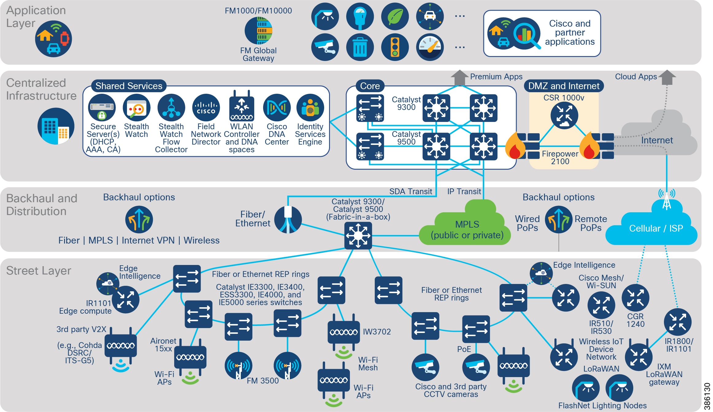
CCI comprises the building blocks shown in CCI Network Architecture and CCI PoP and RPoP.
Figure 2 CCI Network Architecture
CCI Modularity
The intent of this CVD is to provide the reader with the best infrastructure guidance for where they are today. Each layer of the CCI architecture is designed to be consumed in modules. The reader only needs to deploy the access technologies that are relevant for them and can add other network access technologies as needed.
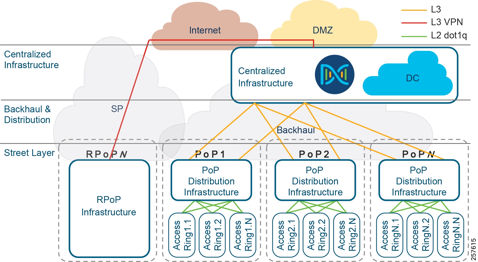
CCI brings intent-based networking out to fiber-connected locations (Points of Presence (PoPs)) and VPN-connected locations (Remote Points of Presence (RPoPs)); all of these locations connect back to some centralized infrastructure via a backhaul, which is where they also access the Internet.
Additional access technologies, such as Wi-Fi, LoRaWAN, CR-Mesh and V2X, can similarly be implemented in a modular approach and will leverage the connectivity provided by CCIs PoPs and RPoPs.
CCI Major Building Blocks
With reference to CCI Network Architecture and CCI PoP and RPoP, what follows is a detailed description of the major building blocks of which CCI is comprised, in terms of the functions, the quantities, the hardware, and interconnection between blocks.
Centralized Infrastructure
Qty 1 of Centralized Infrastructure:
Designs are based on a centralized infrastructure at a single physical site/location. CCI 2.1 works within the boundaries and design rules for SD-Access 2.2.3.3. For more information, please refer to the Cisco Validated Design Software-Defined Access Design Guide at the following URL:
The Centralized Infrastructure is comprised of:
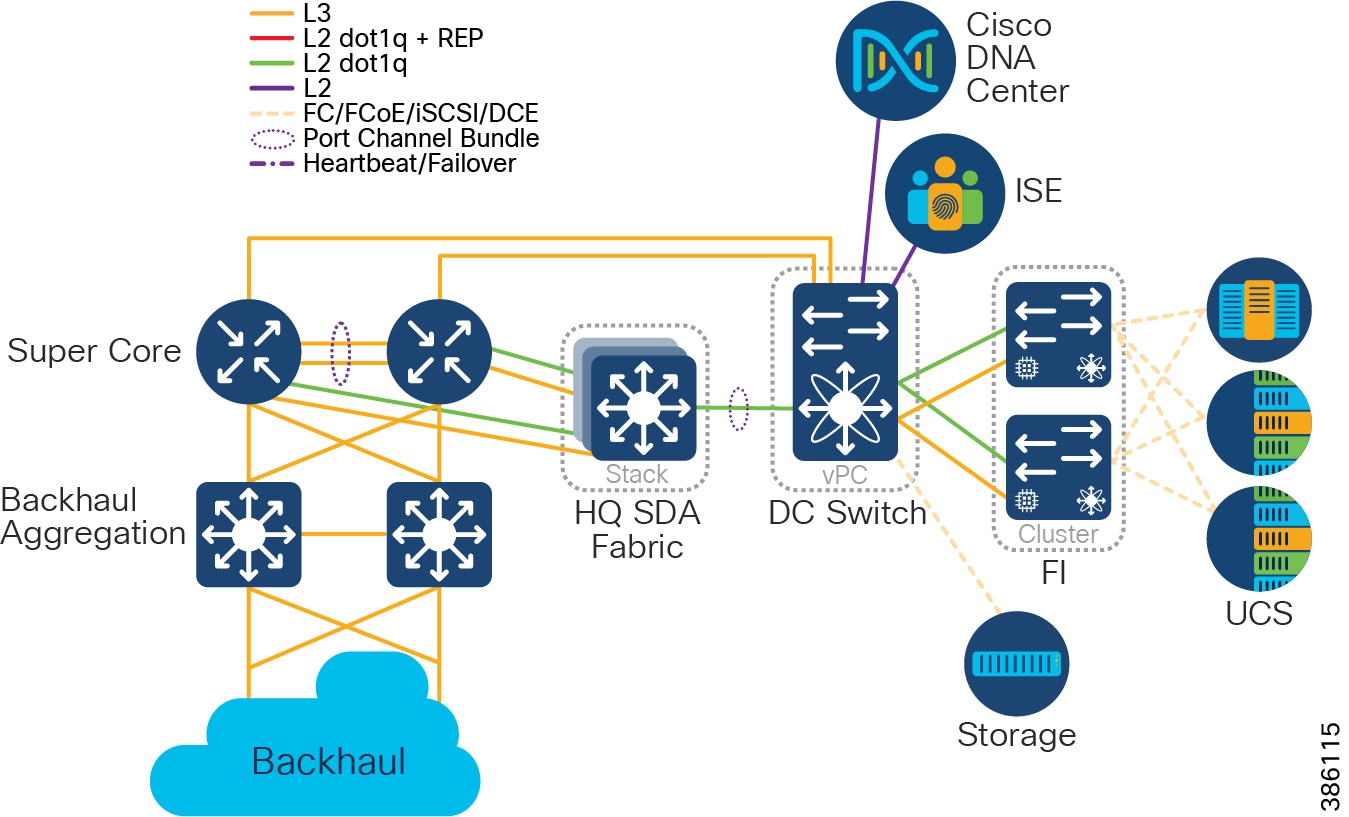
- Cisco UCS 6300 Series Fabric Interconnects (FI) (as resilient pair(s) to provide Data Communications Equipment (DCE) and management of Cisco Unified Computing System (UCS).
- Cisco Nexus 5600 converged DC switches to provide Fiber Channel (FC), Fiber Channel over Ethernet (FCoE), and IP.
- Cisco UCS B and C-series servers connected at a minimum of 10Gbps to FIs.
- Storage, connected at a minimum of 8Gbps to Nexus, via FC, FCoE, or Internet Small Computer Systems Interface (iSCSI).
Note: Application Layer may optionally be entirely delivered from the Public Cloud; if so, no on-premises Application Server infrastructure is required.
- Qty 1 of Super Core, which is comprised of a pair of suitably sized Layer 3 boxes, which provide resilient core and fusion routing capabilities; note that these may be switches even though they are routing.
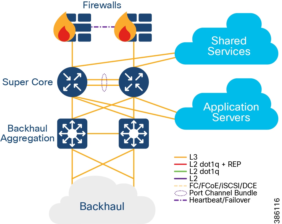
–![]() The Super Core connects to multiple components, and this should be as resilient ≥ 10Gbps L3 links:
The Super Core connects to multiple components, and this should be as resilient ≥ 10Gbps L3 links:
- Shared Services
- DMZ and Internet
- Application Servers
- Point of Presence (PoP) Backhaul
- Qty 1 of De-militarized Zone (DMZ) and Internet:
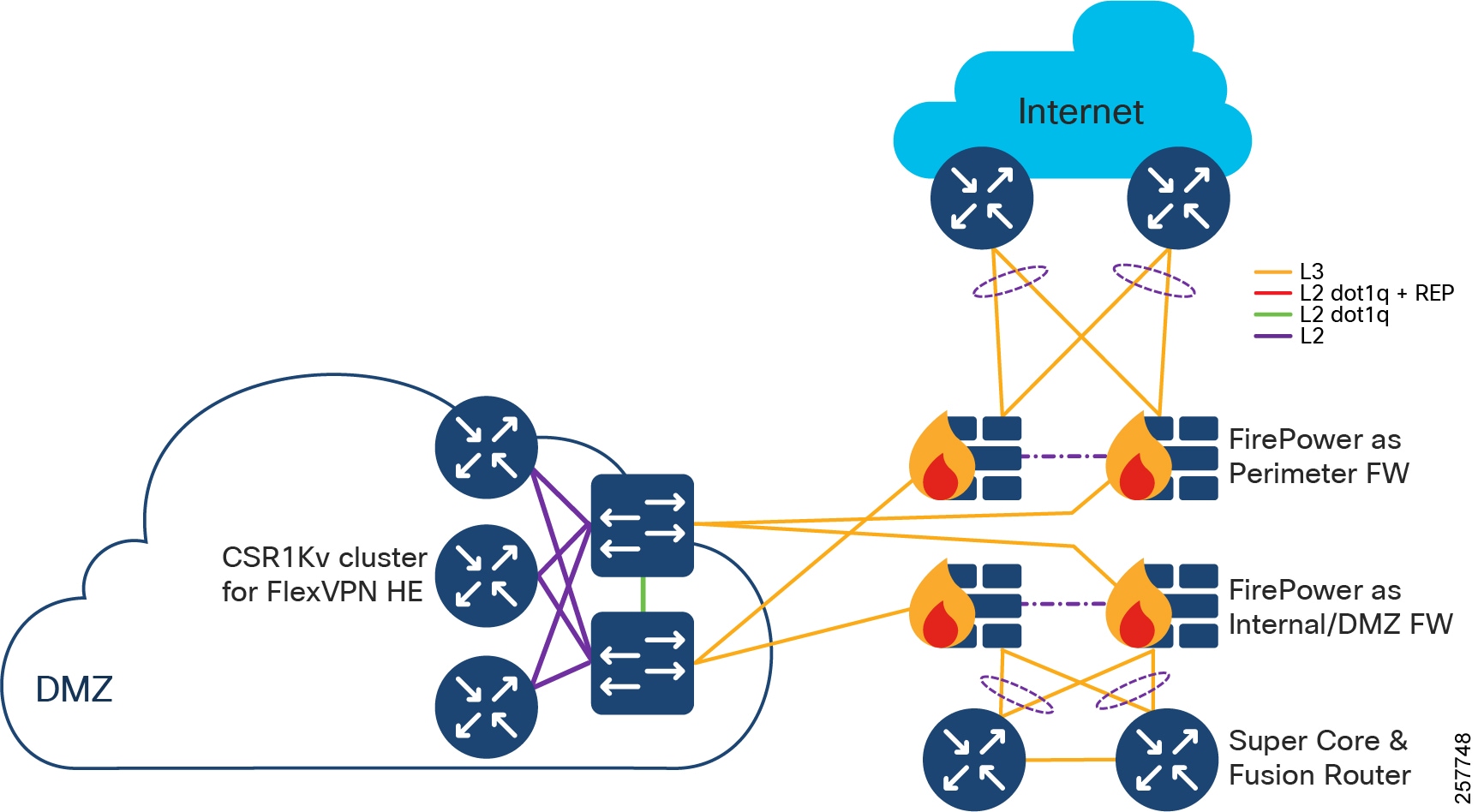
–![]() DMZ is comprised of resilient pairs/clusters of firewalls on both the Internet and DMZ sides, and also a resilient pair/cluster of IPSec headend routers for FlexVPN tunnel termination:
DMZ is comprised of resilient pairs/clusters of firewalls on both the Internet and DMZ sides, and also a resilient pair/cluster of IPSec headend routers for FlexVPN tunnel termination:
- DMZ can optionally contain other servers/appliances that are required by customer for various use cases.
–![]() Qty 1 of Internet connection:
Qty 1 of Internet connection:
- Internet should ideally connect from two different ISPs, or separate A and B connections from a single ISP.
- Qty 1 of Shared Services:
Point of Presence (PoP)
Qty ≤ 499 of Point(s) of Presence
PoPs are typically required, although in some deployments of CCI no PoPs may be required. Note that, a CCI deployment may consist entirely of Remote PoPs (RPoPs) if all-cellular connectivity is used for backhaul.
Points of Presence are comprised of:
–![]() Distribution Infrastructure is comprised of Cisco Catalyst 9000-series switches that are capable of being Fabric in a Box (FiaB); typically 2 x Catalyst 9300 in a physical stack or 2 x Catalyst 9500 switches in a virtual stack (n.b. only the non-High-performance variants of the Catalyst 9500 family are supported).
Distribution Infrastructure is comprised of Cisco Catalyst 9000-series switches that are capable of being Fabric in a Box (FiaB); typically 2 x Catalyst 9300 in a physical stack or 2 x Catalyst 9500 switches in a virtual stack (n.b. only the non-High-performance variants of the Catalyst 9500 family are supported).
–![]() Multi-chassis EtherChannel (MEC) is employed for downlinks to Extended Nodes (ENs) and Policy Extended Nodes (PENs)
Multi-chassis EtherChannel (MEC) is employed for downlinks to Extended Nodes (ENs) and Policy Extended Nodes (PENs)
–![]() Layer 3 P2P uplinks used for connection to the backhaul:
Layer 3 P2P uplinks used for connection to the backhaul:
- to PE routers, in the case of IP Transit (likely SP MPLS)
- to (likely) Catalyst 9500s, in the case of SD-Access Transit, over dark fiber (or equivalent)
- Qty ≥ 1 Access Rings, which are comprised of:
–![]() Qty 1<29 Cisco Industrial Ethernet (IE) switches as extended nodes or policy extended nodes; these switches are either end of a closed Resilient Ethernet Protocol (REP) ring, plus
Qty 1<29 Cisco Industrial Ethernet (IE) switches as extended nodes or policy extended nodes; these switches are either end of a closed Resilient Ethernet Protocol (REP) ring, plus
–![]() IE switches are connected together in a closed ring topology via fiber or copper Small Form-Factor Pluggables (SFP).
IE switches are connected together in a closed ring topology via fiber or copper Small Form-Factor Pluggables (SFP).
–![]() Extended nodes and/or Policy Extended Nodes are connected to uplink Catalyst 9300 stack or Catalyst C9500 StackWise Virtual switches via fiber or copper:
Extended nodes and/or Policy Extended Nodes are connected to uplink Catalyst 9300 stack or Catalyst C9500 StackWise Virtual switches via fiber or copper:
- A ring can be comprised uniformly of all IE-3300, Cisco Embedded Services 3300 Series switches (ESS 3300), IE-4000, or IE-5000 switches, or a mixture of these switches; each operating as an Extended Node
- A ring can alternatively be comprised exclusively of all IE-3400 switches, these operating as Policy Extended Nodes.
- Note: A mix PENs and ENs in the same access ring is not supported.
- Per Points of Presence, nodes of the ring are either daisy-chained Extended nodes or daisy-chained Policy Extended Nodes provisioned through Cisco DNA Center. Please note that it is not possible to mix PENs and ENs in the same access ring.
- SR or LR SFPs can be used, giving fiber distances of <100m to 70km, with RGD optics allowing deployment in the -40 degrees centigrade +85 degrees centigrade temperature range.
Note: Although the SFPs have this operating temperature range, the real-world operating temperature range will be determined by several factors, including the operating temperature range of the switches they are plugged into.
- Different segments of a ring can be different physical lengths/distances and fiber types.
- Qty 2 of 10 Gigabit Ethernet SFP per switch for a 10 Gbps ring:
–![]() Extended nodes connected to uplink Catalyst 9300 stack or Catalyst C9500 StackWise Virtual switches via 10G fiber:
Extended nodes connected to uplink Catalyst 9300 stack or Catalyst C9500 StackWise Virtual switches via 10G fiber:
Backhaul for Points of Presence
To connect the PoPs back to the Centralized Infrastructure, a Metropolitan Area Network (MAN) is used.
Figure 8 Backhaul for Points of Presence
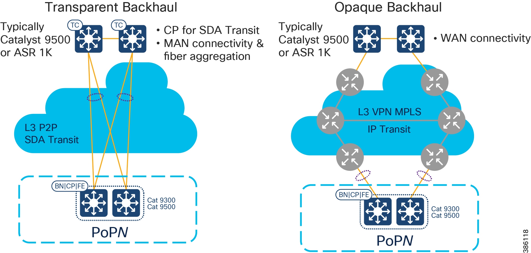
When deploying CCI, you may have access to dark fiber, in which case you can build your own MAN, which is a transparent backhaul entirely within the SD-Access fabric domain that uses SD-Access Transit. Alternatively, or additionally, an SP might be involved or you might have your own MPLS network; this is an opaque backhaul and the traffic must leave the SD-Access fabric domain on an IP Transit and come back into the SD-Access fabric domain at the far side.
Remote Point of Presence (RPoP)
- Qty ≤ 1000 of Remote Points-of-Presence (RPoPs); although in some deployments of CCI no RPoPs may be required.
- An RPoP is a Connected Grid Router (CGR) or Cisco Industrial Router (IR) and is typically connected to the Public Internet via a cellular connection (although any suitable connection can be used (such as xDSL or Ethernet), over which FlexVPN secure tunnels are established to the HE in the DMZ.
- The RPoP router may provide enough local LAN connectivity, or an additional Cisco Industrial Ethernet (IE) switch may be required.
CCI's Cisco Software-Defined Access Fabric
The SD-Access Fabric Network Layers of CCI
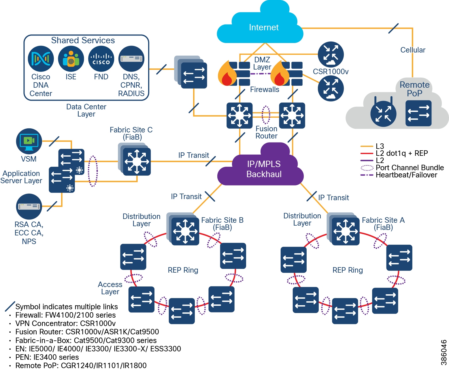
The CCI Network design based on the SD-Access framework follows the design principles and best practices associated with a hierarchical design by splitting the network into modular groups, as described in the Campus LAN and Wireless LAN Design Guide. The modular building blocks can be replicated, which makes it an optimal and scalable architecture. The network is a multi-tier architecture with access, distribution, core, data center, application server, DMZ, and Internet layers. The overall CCI network architecture with IP Transit is shown in CCI Network Diagram with IP Transit.
At the heart of the CCI network is the Cisco DNA Center with SD-Access, which is the single-pane-of-glass management and automation system. The CCI network spreads across a large geographical area, logically divided into several PoPs. Each PoP is designed as a fabric site.
Each fabric site (PoP) consists of the Fabric in a Box (FiaB), which is a consolidated fabric node. FiaB plays the role of a distribution layer by consolidating the access layer traffic and acting as the fabric site gateway to the core. The access layer consists of one or more REP rings of Cisco Industrial Ethernet Switches.
Multiple fabric sites across the city or along the roadway are interconnected by either SD-Access Transit or IP Transit to give a multi-site/distributed topology. A CCI Network deployment can have IP Transit or SD-Access Transit or both. The CCI Network Design with IP Transit illustrates a CCI Network design with only IP Transit, whereas The CCI Network Design having both SD-Access and IP Transit shows a CCI Network design with both SD-Access transit and IP-Transit.
A fusion router interconnects the fabric and all fabric sites with the shared services and Internet.
The application servers are hosted in an exclusive fabric site for end-to-end segmentation. The Internet breakout is centralized across all the fabric sites and passes through the firewall at the DMZ. The Cisco DNA Center needs to have Internet access for regular cloud updates. Important design considerations such as redundancy, load balancing, and fast convergence are to be ensured at every layer/critical node/critical link of the network. This will ensure uninterrupted service and optimal usage of the network resources.
Upcoming sections in this document elaborate each of these components. For more information, please refer to the Campus LAN and Wireless LAN Design Guide at the following URL:
The CCI Network Design with IP Transit
CCI Network Diagram with IP Transit shows the CCI Network design with IP Transit. Multiple network sites (PoP locations) are interconnected by an IP/MPLS backbone configured by SD-Access as IP Transit. IP Transit Network elaborates on IP Transit.
Figure 9 CCI Network Diagram with IP Transit
The CCI Network Design having both SD-Access and IP Transit
CCI Network Having Both SD-Access Transit and IP Transit shows the CCI Network design having both SD-Access and IP Transit. The network sites that have a campus like connectivity (high speed, low latency, and Jumbo MTU support) with Cisco DNA Center are interconnected with SD-Access Transit. The network sites that have a WAN like IP/MPLS backbone are interconnected with IP Transit. A core device called a Fusion Router interconnects shared services and Internet to all fabric sites in the network, regardless of their backhaul.
Figure 10 CCI Network Having Both SD-Access Transit and IP Transit

Underlay Network
In order to set up an SD-Access-managed network, all managed devices need to be connected with a routed underlay network, thus being IP reachable from the Cisco DNA Center. This underlay network can be configured manually or with the help of the Cisco DNA Center LAN Automation feature. Note that Cisco DNA Center LAN automation has a maximum limit of two hops from the configured seed devices and does not support Cisco Industrial Ethernet (IE) Switches. Because the CCI network has Cisco Industrial Ethernet (IE) switches and most CCI network deployments will have more than two hops, manual underlay configuration is recommended for CCI.
The SD-Access design recommendation is that the underlay should preferably be an IS-IS routed network. While other routing protocols can be used, IS-IS provides unique operational advantages such as neighbor establishment without IP protocol dependencies, peering capability using loopback addresses, and agnostic treatment of IPv4, IPv6, and non-IP traffic. It also deploys both a unicast and multicast routing configuration in the underlay, aiding traffic delivery efficiency for services built on top. However, other routing protocols such as Enhanced Interior Gateway Routing Protocol (EIGRP) and Open Shortest Path First (OSPF) can also be deployed, but these may require additional configuration.
Underlay connectivity spans across the fabrics, covering Fabric Border Node (BN), Fabric Control Plane (CP) node, Intermediate nodes, and Fabric Edges (FE). Underlay also connects the Cisco DNA Center, Cisco ISE, and the fusion router. However, all endpoint subnets are part of the overlay network.
Note: The underlay network for the SD Access fabric requires increased MTU to accommodate additional overlay fabric encapsulation header bytes. Hence, you must increase the default MTU to9100bytesto ensure that Ethernet jumbo frames can be transported without fragmentation inside the fabric.
Refer to the SD-Access Design and Deployment Guides for further underlay design and deployment details.
Overlay Network
An SD-Access fabric creates virtualized networks (VNs) on top of the physical underlay network, called overlay. These VNs can span the entire fabric and remain completely isolated from each other. The entire overlay traffic, including data plane and control plane, are contained fully within each VN. The boundaries for the fabric are the BN and FE nodes. BN is the ingress and egress point to the fabric, FE is the entry point for wired clients, and Fabric Wi-Fi AP is the entry point for Wi-Fi wireless clients.
The VNs are realized by virtual routing and forwarding (VRF) instances and each VN appears as a separate instance for connectivity to the external network. SD-Access overlay can be either Layer 2 overlay or Layer 3. For the CCI network, Layer 3 overlay is chosen as the default option. The Layer 3 overlay allows multiple IP networks as part of each VN. Overlapping IP address space across different Layer 3 overlays is not recommended in the CCI network for administrative convenience and to avoid the need for network address translation (NAT) for shared services that span across VNs.
Within the SD-Access fabric, the user and control data are encapsulated and transported using the overlay network. The encapsulation header carries the virtual network and SGT information, which is used for traffic segmentation within the overlay network.
Segmentation allows granular data plane isolation between groups of endpoints within a VN and allows simple-to-manage group-based policies for selective access. The SGTs also aid scalable deployment of policy avoiding cumbersome IP-based policies.
VNs provide macro-segmentation by isolation of both data and control plane, whereas segmentation with SGT provides micro-segmentation by selective separation of groups within a VN.
By default, no communication between VNs is possible. If communication is needed across VNs, a fusion router outside the fabric can be employed with appropriate “route-leaking” configuration for selective inter-VN traffic communication; however, communication within a VN (same or different SGT) is routed within the fabric.
Following the SD-Access design recommendations, minimizing the number of IP subnets is advised to simplify the Dynamic Host Configuration Protocol (DHCP) management. The IP subnets can be stretched across a fabric site without any flooding concerns, unlike large Layer 2 networks. IP subnets should be sized according to the services that they support across the fabric. However, based on the deployment needs of enabling optional broadcast feature, the subnet size can be limited. In this context, a “service” may be a use case: for example, how many IPv4 Closed Circuit Television (CCTV) cameras am I going to deploy across my entire city (now and into the future), and how many back-end servers in my DC do I need to support them?
Fabric Data Plane and Control Plane
This section provides a detailed explanation of how the fabric data and control plane work. All of this is automated by SDA and largely hidden from the administrator; therefore, this section can be skipped unless the reader wishes to go very deep.
Within the SD-Access fabric, SD-Access configures the overlay with fabric data plane by using Virtual Extensible LAN (VXLAN). RFC 7348 defines the use of VXLAN as a way to overlay a Layer 2 network on top of a Layer 3 network. VXLAN encapsulates and transports Layer 2 frames across the underlay using UDP/IP over Layer 3 overlay. Each overlay network is called a VXLAN segment and is identified by a VXLAN Network Identifier (VNI). The VXLAN header carries VNI and SGT needed for macro- and micro-segmentation. Each VN maps to a VNI, which, in turn, maps to a VRF in the Layer 3 overlay.
Along with VXLAN data plane, SD-Access uses Location/IP Separation Protocol (LISP) as control plane. From a data plane perspective, each VNI maps to a LISP Instance ID. LISP helps to resolve endpoint-to-location mapping. LISP does perform routing based on End Point Identifier (EID) and Routing Locator (RLOC) IP addresses. An EID could be either an endpoint IP address or MAC. An RLOC is part of underlay routing domain, which is typically the Loopback address of the FE node to which the EID is attached. The RLOC represents the physical location of the endpoint. The combination of EID and RLOC gives device ID and location; thus, the device can be reached even if it moves to a different location with no IP change. The RLOC interface is the only routable address that is required to establish connectivity between endpoints of the same or different subnets.
Within the SD-Access fabric, LISP provides control plane forwarding information; therefore, no other routing table is needed. To communicate external to the SD-Access fabric, at the border each VN maps to a VRF instance. Outside the fabric path, isolation techniques such as VRF-Lite or MPLS may be used to maintain the isolation between VRFs. EIDs can be redistributed into a routing protocol such as Border Gateway Protocol (BGP), EIGRP, or OSPF for use in extending the virtual networks.
To provide forwarding information, LISP map server, located on the CP node, maintains EID (host IP/MAC) to RLOC mapping in its map-server. The local node queries the control plane to fetch the destination EID route.
Fabric Border
Fabric Roles and Terminology depicts different fabric roles and terminology in Cisco SD-Access design. Fabric Border (BN) is the entry and exit gateway between the SD-Access fabric site and networks external to the fabric site. Depending on the types of outside networks it connects to, BN nodes can be configured in three different roles: Internal Border (IB), External Border (EB), and Anywhere Border (AB). The IB connects the fabric site to known areas internal to the organization such as the data center (DC) and application services. The EB connects a fabric site to a transit as an exit path for the fabric site to outside world, including other fabric sites and the Internet. AB, however, connects the fabric site to both internal and external locations of the organization. The aggregation point for the exiting traffic from the fabric should be planned as the border; traffic exiting the border and doubling back to the actual aggregation point results in sub-optimal routing. In CCI, each PoP site border is configured with EB role connecting to a transit site and HQ/DC fabric site border is configured with AB role to provide connectivity to internal and external locations.
Figure 11 Fabric Roles and Terminology
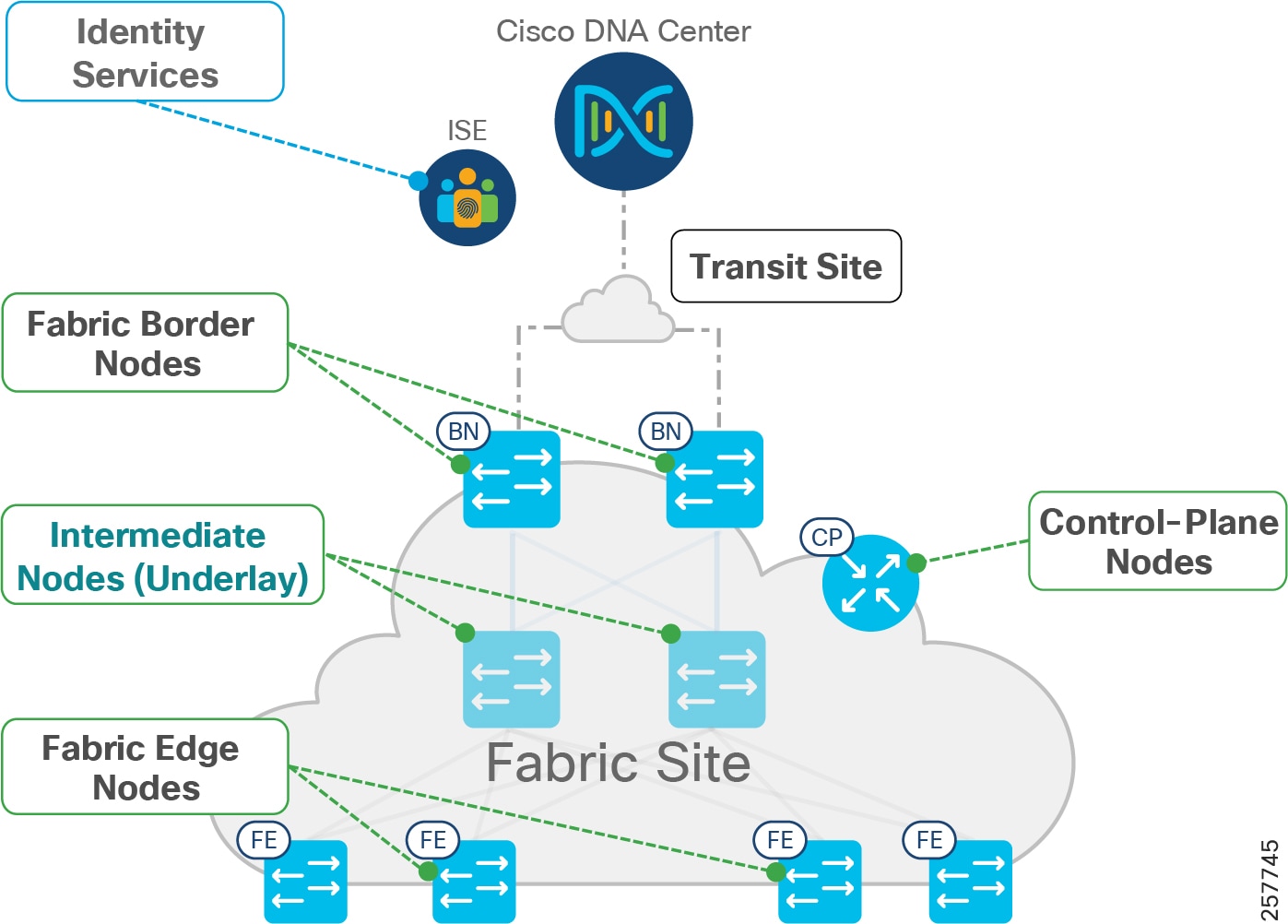
In general, the fabric BN is responsible for network virtualization interworking and SGT propagation from the fabric to the rest of the network. The specific functionality of the BN includes:
- Gateway for the fabric to reach the world outside the fabric
- Advertising EID subnets of the fabric to networks outside the fabric for them to communicate with the hosts of the fabric, via BGP
- Mapping LISP instances to VRF instances to preserve the virtualization
- Propagating SGT to the external network either by transporting tags using SGT Exchange Protocol (SXP) to Cisco TrustSec-aware devices or using inline tagging in the packet
The EID prefixes appear only on the routing tables at the border; throughout the rest of the fabric, the EID information is accessed using the fabric control plane (CP).
Fabric Edge
Fabric edge nodes (FEs) are access layer devices that provide Layer 3 network connectivity to end-hosts or clients addressed as endpoints. The fundamental functions of FE nodes include endpoint registration, mapping endpoints to virtual networks, and segmentation and application/QoS policy enforcement.
Endpoints are mapped to VN by assigning the endpoints to a VLAN associated to a LISP instance. This mapping of endpoints to VLANs can be done statically (in the Cisco DNA Center user interface) or dynamically (using 802.1X and MAB). Along with the VLAN, an SGT is also assigned, which is used to provide segmentation and policy enforcement at the FE node.
Once a new endpoint is detected by the FE node, it is added to a local host tracking database EID-Table. The FE node also issues a map-registration message to the LISP map-server on the control plane node to populate the Host Tracking Database (HTDB).
On receipt of a packet at the FE node, a search is made in its local host tracking database (LISP map-cache) to get the RLOC associated with the destination EID. In case of a miss, it queries the map-server on the control plane node to get the RLOC. In case of a failure to resolve the destination RLOC, the packet is sent to the default fabric border. The border forwards the traffic using its global routing table.
If the RLOC is obtained, the FE node uses the RLOC associated with the destination IP address to encapsulate the traffic with VXLAN headers. Similarly, VXLAN traffic received at a destination RLOC is de-encapsulated by the destination FE.
If traffic is received at the FE node for an endpoint not locally connected, a LISP solicit-map-request is sent to the sending FE node to trigger a new map request; this addresses the case where the endpoint may be present on a different FE switch.
Fabric-in-a-Box (FiaB)
For smaller fabric sites, such as a CCI PoP, all three fabric functions (Border, Control, and Edge) can be hosted in the same physical network device; this is known as “Fabric in a Box” (FiaB).
In the current release of CCI, the FiaB model is recommended based on the size of the network and size of the traffic to be supported from a fabric site. For size calculations, see CCI Network Access Layer Dimensioning.
Extended Nodes and Policy Extended Nodes
Extended Node
The SD-Access fabric can be extended with the help of extended nodes. Extended nodes are access layer Ruggedized Ethernet switches that are connected directly to the Fabric Edge/FiaB. The list of DNA Center 2.2.3-supported extended node devices used in CCI network include the Cisco IE4000 series, the Cisco IE5000 series switches the Cisco IE3300 series switches and the Cisco ESS3300 switches.
Cisco IE3400 series switches can be configured as Policy Extended Node (PEN) being a superset of Extended Node. Refer to the “ Policy Extended Node ” section below for more details on IE3400 switches role in CCI PoP. These Ruggedized Ethernet switches are connected to the Fabric Edge or FiaB in a daisy-chained linear, star, and ring topologies for Ethernet access network high availability. Refer to the section “Ethernet Access Network” in this document, for more details on Ethernet daisy-chained, linear, star and ring topologies design in CCI.
Extended nodes support VN based macro-segmentation in the Ethernet access ring. These devices do not natively support fabric technology. Therefore, policy enforcement for the traffic generated from the extended node devices is done by SD-Access at the Fabric Edge.
The daisy-chained ENs do all of the endpoint onboarding connected to its ports, but policy is applied only to traffic passing through the FE/FiaB nodes. The extended nodes support 802.1X or MAB based Closed Authentication for Host Onboarding in Cisco DNA Center Fabric provisioning.
The rationale for recommending ring topology with REP for Cisco Industrial Ethernet (IE) switches to provide Ethernet access is discussed in “Ethernet Access Network”. Both ends of REP ring are terminated at FE/FiaB, such that all Cisco Industrial Ethernet (IE) switches in the ring and FiaB are part of closed REP segment.
Policy Extended Node
Cisco DNA Center 2.2.3 also supports “Policy Extended Node” which is a construct at Ethernet access ring capable of doing group based micro-segmentation for improved Ethernet access ring security. Cisco IE3400 series switches support this functionality with Network Advantage and DNA Advantage licenses. IE3400 switches must have Network Advantage and DNA advantage licenses to operate as Policy Extended Node. The policy extended nodes are capable of doing Scalable Group Tag (SGT) based inline tagging and enforcing SGACL based security policies for device to device communication within a VN or domain.
Cisco TrustSec (CTS) architecture consists of authentication, authorization and services modules like guest access, device profiling etc., TrustSec is an umbrella term and it covers anything to do with endpoint’s identity, in terms of IEEE 802.1X (dot1x), profiling technologies, guest services, Scalable Group based Access (SGA) and MACSec (802.1AE). CTS simplifies the provisioning and management of secure access to network services and applications. Compared to access control mechanisms that are based on network topology, Cisco TrustSec defines policies using logical policy groupings, so secure access is consistently maintained even as resources are moved in mobile and virtualized networks.
CTS classification is done by Cisco ISE and policy enforcement is done on Cisco switching, routing, wireless LAN, and firewall products. By classifying traffic based on the contextual identity of the endpoint versus its IP address, Cisco TrustSec enables more flexible access controls for dynamic networking environments. At the point of network access, a Cisco TrustSec policy group called a Security Group Tag (SGT) is assigned to an endpoint, typically based on that endpoint’s user, device, and location attributes. The SGT denotes the endpoint’s access entitlements, and all traffic from the endpoint will carry the SGT information.
The PEN supports CTS and 802.1X or MAB based Closed Authentication for host onboarding along with dynamic VLAN and SGT attributes assignment for endpoints, in Cisco DNA Center Fabric provisioning. It requires the policy extended nodes to communicate with ISE to authenticate and authorize the endpoints for downloading the right VLANs and SGT attributes.
A feature comparison of Extended Node and Policy Extended Node is shown in Table 1.
Endpoints
The clients or user devices that connect to the Fabric Edge Node are called Endpoints; supported downstream switches are Extended Nodes or Policy Extended Nodes. In the case of CCI Network, wired and wireless clients connect directly or indirectly via APs or gateways to access switches that are either ENs or PENs. For uniformity in this document, we refer to all of the wired and wireless clients as “Endpoints.”
Transit Network
Fabric domain is a single fabric network entity consisting of one or more isolated and independent fabric sites. Multiple fabric sites can be connected with a transit network. Depending on the characteristics of the intermediate network interconnecting the fabric sites and Cisco DNA Center, the transit network can either be SD-Access Transit or IP Transit. Typically, an IP-based Transit connects a fabric site to an external network whereas SD-Access Transit connects one or more native fabric sites.
SD-Access Transit Network
The key consideration for using SD-Access transit is that the network between the fabric sites and the Cisco DNA Center should be created with campus-like connectivity. The connections should be high-bandwidth and low latency (less than 10ms) and should accommodate jumbo MTUs (9100 bytes). These are best suited when dark fiber is available between fabric sites. The larger MTU size is needed to accommodate an increase in packet size due to VXLAN encapsulation, therefore, avoiding fragmentation and reassembly.
An SD-Access Transit consists of a domain-wide control plane node dedicated to the transit functionality, connecting to a network that has connectivity to the native SD-Access (LISP, VXLAN, and CTS) fabric sites that are to be interconnected as part of the larger fabric domain. Aggregate/summary route information is populated by each of the borders connected to the SD-Access Transit control plane node using LISP.
SD-Access Transit carries SGT and VN information, with native SD-Access VXLAN encapsulation, inherently enabling policy and segmentation between fabric sites; in that way, segmentation is maintained across the fabric sites in a seamless manner.
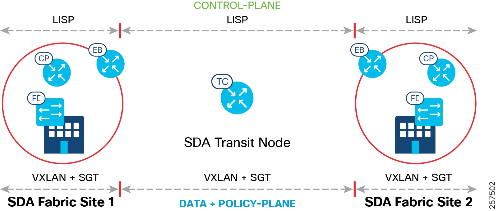
End-to-end configuration of SD-Access Transit is automated by the Cisco DNA Center. The control, data, and policy plane mapping across the SD-Access Transit is shown in SD-Access Transit Data, Control, and Policy Plane Mapping. Two SD-Access Transit Control (TC) plane nodes are required, but these are for control plane signaling only and do not have to be in the data plane path.
Note: SD-Access Transit Control Plane functionality can be co-located in the WAN aggregation or border routers or it can also be deployed in a separate pair of switches or routers in CCI deployments.
Figure 12 SD-Access Transit Data, Control, and Policy Plane Mapping
IP Transit Network
IP Transit is the choice when the fabric sites are connected using an IP network that doesn't comply to the desired network specification of SD-Access Transit, such as latency and MTU. This is often the choice when the fabric sites are connected via public WAN circuits.
Unlike SD-Access Transit, the configurations of intermediate nodes connecting fabric sites in IP-Transit are manual and not automated by Cisco DNA Center.
IP Transits offer IP connectivity without native SD-Access encapsulation and functionality, potentially requiring additional VRF and SGT mapping for stitching together the macro- and micro-segmentation needs between sites. Traffic between sites will use the existing control and data plane of the IP Transit area. Thus, the ability to extend segmentation across IP transit depends on the external network.
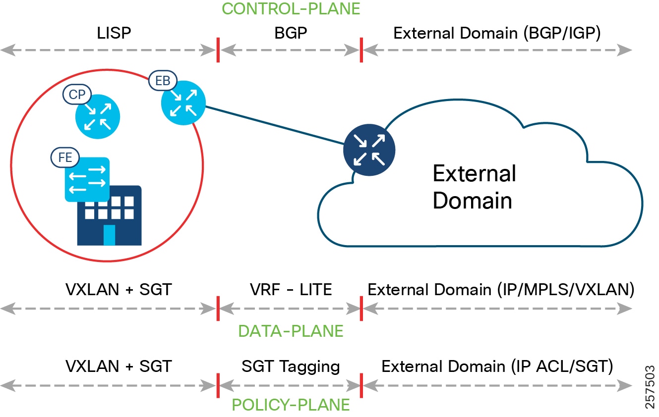
Unlike SD-Access transit, no dedicated node does IP Transit functionality. Instead, the traditional IP handover functionality is performed by the fabric border node. Border nodes hand off the traffic to the directly connected external domain (BGP with VRF-LITE or BGP with MPLS VRF). BGP is the supported routing protocol between the border and external network. The router connecting to the border at the HQ site is also configured for fusion router functionality with selective route leaking. Fusion router is explained in the next section below. The list of VNs that need to communicate with the external network are selected at the border IP Transit interface.
The list of VNs that need to communicate with the external world are selected at the border IP Transit interface.
As discussed previously, IP Transit is outside of the fabric domain, therefore SXP is used to re-apply the correct markings (VXLAN and SGT) that are stripped off during the transit.
The control, data, and policy plane mapping from the SD-Access fabric to the external domain is shown in IP Transit Data, Control, and Policy Plane Mapping. Multiple fabric sites can interconnect via external network using IP Transit.
Figure 13 IP Transit Data, Control, and Policy Plane Mapping
Fusion Router
Most of the networks will need to connect to the Internet and shared services such as DHCP, DNS, and the Cisco DNA Center. Some networks may also have a need for restricted inter-VN communication. Inter-VN communication is not allowed and not possible within a Fabric Network.
To accommodate the above requirements at the border of the fabric, a device called a fusion router (FR) or fusion firewall is deployed. The border interface connecting to FR is an IP Transit. The FR/fusion firewall is manually configured to do selective VRF route leaking of prefixes between the SD-Access virtual networks and the external networks. The FR governs the access policy using ACLs, between the VRFs and the Global Routing Table (GRT). Use of the firewall as a FR gives an additional layer of security and monitoring of traffic between virtual networks.
Access Networks
CCI is versatile and modular, allowing it to support different kinds of access networks. Different CCI solutions such as Smart Lighting, Smart Parking, Safety and Security, and Connected Roadways have different access networks needs and can seamlessly use CCI as a common network infrastructure.
The list of access networks included in this release are:
- CCI Ethernet access network solution
- CCI Wi-Fi 802.11 access network solution
- CCI CR-Mesh (802.154g/e) access network solution (Wi-SUN certified)
- CCI LoRaWAN access network solution
Note: The physical installation of access networking around or on the street/roadway is very different than that of a typical enterprise network; extra care should be taken with respect to environment conditions and rating of equipment (and associated enclosures), as well as the physical security of the network equipment: for example, is it pole-mounted high enough out of reach? Is the enclosure securely locked?
Solution Components
The components of the CCI network are listed in this chapter. Several device models can be used at each layer of the network. The suitable platform of devices for each role in the network and the corresponding CVD-validated software versions are presented in CCI Network Components. To find a list of supported devices, refer to the SD-Access 2.x product compatibility matrix at the following URL:
https://www.cisco.com/c/dam/en/us/td/docs/Website/enterprise/sda_compatibility_matrix/index.html
The exact suitable model can be chosen from the suggested platform list to suit specific deployment requirements such as size of the network, cabling and power options, and access requirements. The components for various CCI general solutions are listed in their respective sections.
Note: In addition to the compatibility matrix, it is recommended to research any product vulnerabilities discovered since publication, via https://tools.cisco.com/security/center/publicationListing.x. This is especially important for ISE and the FlexVPN headend.
** Refer to the URL below for the list of Cisco Catalyst 9500 standard and high performance series of switches that support SVL:
Table 3 Cisco Ultra-Reliable Wireless Backhaul (CURWB) Components
* The Train Radio is not part of the trackside infrastructure. The FM 4500 resides on the train to communicate with the FM 3500 on the trackside.
CCI Switched Ethernet Access Network (PoPs)
This chapter discusses design for CCI Ethernet Access Network for endpoint connectivity.
Ethernet access is provided by connecting Cisco Industrial Ethernet (IE) Ethernet switches to Fabric Edge/FiaB. The Cisco Industrial Ethernet series switches are modular and scalable with various options for 10/10/1000Mbps copper/fiber ports with PoE/PoE+ support. A snapshot of the Cisco Industrial Ethernet (IE) switch portfolio is given in CCI Network Access, Distribution, and Core Layer Portfolio Comparison. The distance covered and number of access ports provided by a single hop of Cisco Industrial Ethernet (IE) Ethernet switch can be highly limiting. Daisy chaining of ENs or PENs provides flexibility for customers to extend the fabric connectivity. Daisy chaining of ENs and PENs in a linear, star and ring topologies are supported. However, multi-hop ring network with REP ring technology is preferred in IoT applications due to distance covered, redundancy, and resiliency features.
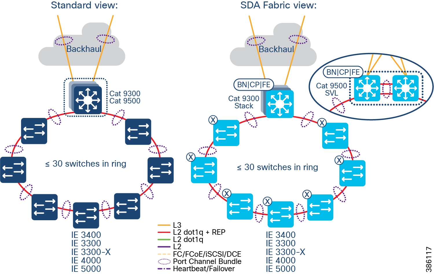
The recommended Ethernet access network topology for CCI is a REP ring formed by Cisco Industrial Ethernet (IE) switches connected back-to-back that terminates both ends of the ring on a stack of Fabric Edge devices. Considering the Ethernet access ring of <30 and multiple such rings in the CCI deployments.
Daisy chaining Linear and Star Topology Design
As part of a CCI setup, Extended nodes (ENs) and Policy Extended Nodes (PENs) can be connected to a stack of C9300 or C9500 switches in a StackWise Virtual (SVL) configuration to operate as Fabric-in-a-Box (FiaB).
The Cisco Digital Network Architecture Center (DNAC) release 2.2.2.3 extended the connection capability of ENs and PENs from a Fabric Edge or FiaB to also connect one EN to EN or PEN to PEN in a daisy chain configuration. Customers can now build topologies connecting to those endpoints regardless of where in the network they are deployed from 2.2.2.3 onwards.
The following switches can be daisy chained to form linear and/or star topologies:
- Cisco IE 4000 series
- Cisco IE 5000 series
- Cisco IE 3300 series including 10G uplink switches
- Cisco ESS 3300 switches with the role of EN
Example topologies are shown in EN Daisy chain in a linear and star topology.
Figure 14 EN Daisy chain in a linear and star topology
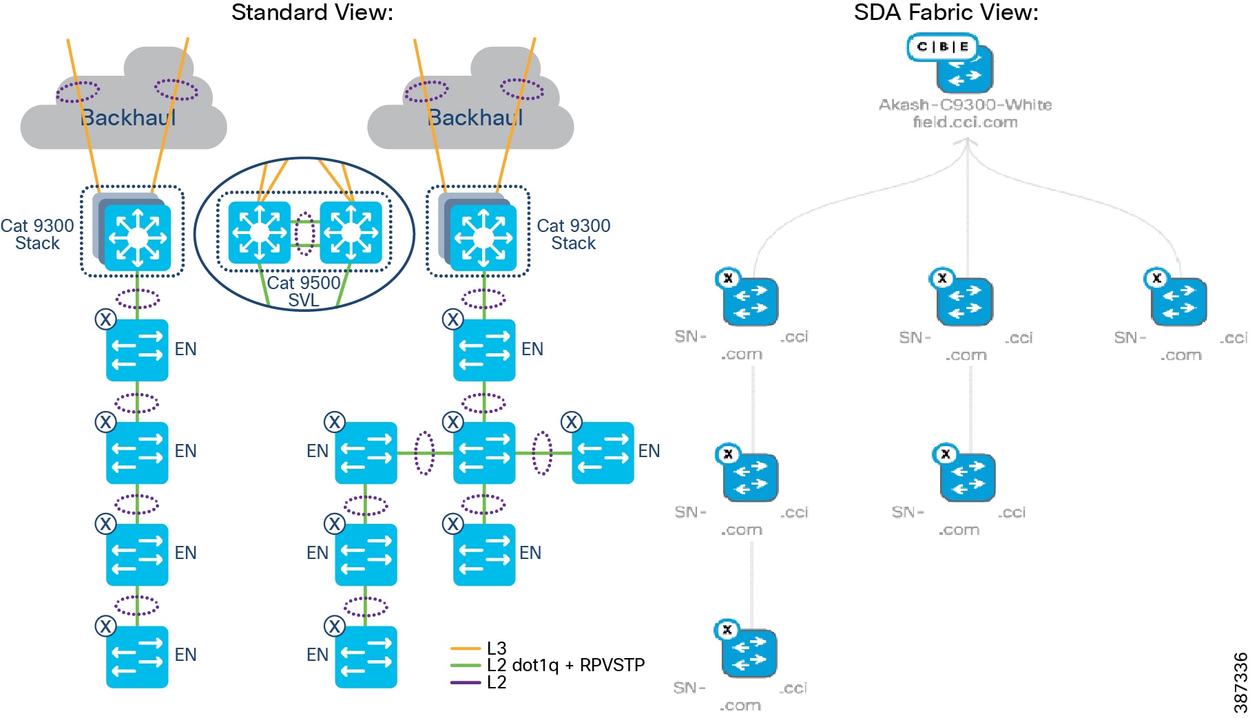
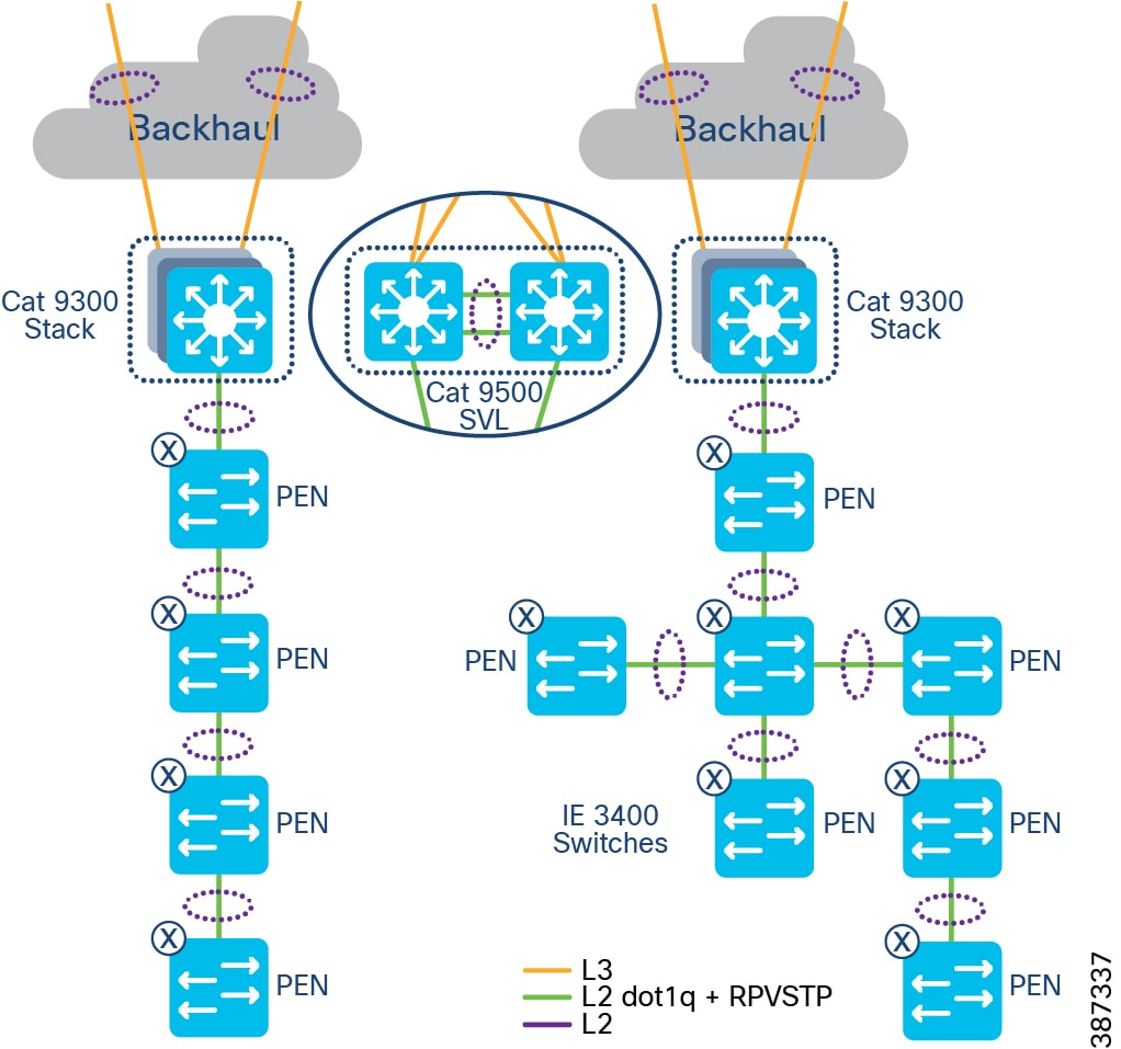
Daisy chained linear and star topologies extend fabric connectivity for endpoints connected to these switches in CCI PoP sites. Cisco IE 3400 series switches with the role of PENs in SD-Access Fabric are daisy chained to form linear and/or star topologies as shown in EN Daisy chain in a linear and star topology.
The Cisco DNA Center release 2.2.3.3 auto-configures PENs in the daisy chain with appropriate SGT, CTS, and SGACL policy configurations. Daisy chained PENs extend the micro-segmentation and policy automation along with SGACL policy enforcement on the destination PEN in the daisy chain. All nodes in the daisy chain are configured with default Rapid Per VLAN Spanning Tree Protocol (RPVSTP).
Figure 15 PEN Daisy chain in a linear and star topology
Design Considerations
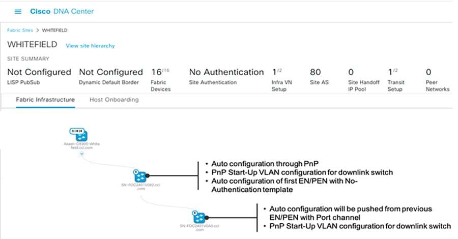
When daisy-chaining EN or PEN devices, the following sequence occurs during PnP:
1.![]() Auto-configuration will happen in the first EN/PEN Device connected to the Fabric edge/FiaB through auto install startup VLAN.
Auto-configuration will happen in the first EN/PEN Device connected to the Fabric edge/FiaB through auto install startup VLAN.
2.![]() The interface connected towards the first EN or PEN is applied with trunk configuration (Switch interface template) and Port channel.
The interface connected towards the first EN or PEN is applied with trunk configuration (Switch interface template) and Port channel.
3.![]() Auto configuration of the initial EN or PEN devices with "No Authentication" template is supported.
Auto configuration of the initial EN or PEN devices with "No Authentication" template is supported.
4.![]() The next set of EN or PEN auto configuration and port channel configurations is pushed from the EN or PEN that was previously provisioned.
The next set of EN or PEN auto configuration and port channel configurations is pushed from the EN or PEN that was previously provisioned.
5.![]() Auto configuration of the next set of EN or PEN devices with "No Authentication" template is supported.
Auto configuration of the next set of EN or PEN devices with "No Authentication" template is supported.
Note: If using the “Open Authentication”, "Close Authentication”, or "Low Impact" templates the Port channels must be created manually. When using “No Authentication”, the Port Channels are created automatically. Additionally, when choosing “No Authentication” at the fabric site level, endpoints will not be authenticated unless explicitly configured using the Host Onboarding workflow.
Topology View of a Linear daisy chain of ENs in a fabric illustrates a topology view and onboarding process of ENs in a CCI PoP.
Figure 16 Topology View of a Linear daisy chain of ENs in a fabric
Limitations and Restrictions of Daisy Chaining
- A mix of PENs and ENs in a single daisy chain is not supported. A daisy chain must be all PENs or ENs.
- PENs and ENs can only connect to one Fabric Edge or FiaB. Dual-homing of one EN to two different Fabric Edges or FiaB is not supported.
- The default maximum size of an EN daisy chain is 18 nodes. This is limited by the default STP max-age timer value of 20 on the STP root bridge. A maximum of 38 ENs or PENs can be provisioned in a single daisy chain by changing the STP max-age timer value to 40 on the FiaB as the STP root bridge.
- Only new REP ring (Greenfield) deployments are supported; an existing daisy chain topology if any (may have been configured using Day N templates) in a PoP cannot migrated using Cisco DNA Center daisy-chaining feature.
- It is recommended to make the Fabric Edge or FiaB the root bridge of the EN spanning tree network. If it is not, the size of other daisy chains of extended nodes connected to same Fabric Edge or FiaB is limited.
- The total number MAC addresses supported is 32,000 for C9300 and C9500 switches used as Fabric Edge or FiaB.
Ring Topology
In this topology, the Cisco Industrial Ethernet (IE) switches are connected to the Fabric Edge or FiaB in a ring form. A default STP ring topology of IE switches can be configured using Cisco DNA Center for deployments where stringent ring failure convergence is not a requirement for endpoints connected to the ring. This section discusses STP and REP access ring topologies in the CCI design.
Spanning Tree Protocol (STP) Ring
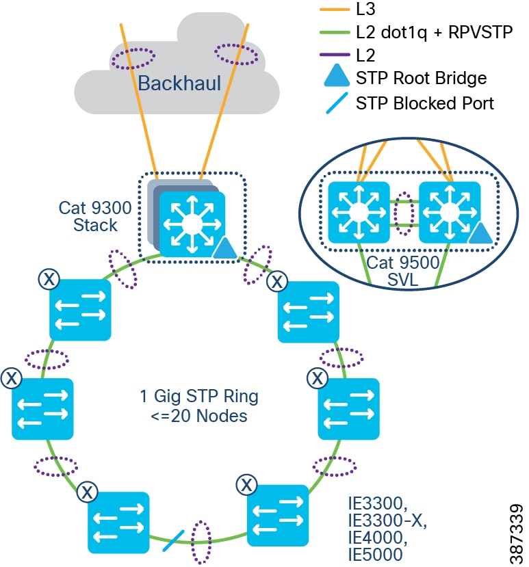
In Spanning Tree Protocol (STP) topology, the Cisco Industrial Ethernet (IE) switches are connected to the Fabric Edge or FiaB in a ring form, as shown in STP ring of Extended Nodes. An STP ring of ENs or PENs topology can be formed by connecting two linear daisy chains of ENs or PENs onboarded using the Cisco DNA Center. An STP ring of ENs/PENs thus formed will have Rapid Per VLAN Spanning Tree Protocol (RPVSTP) enabled for loop avoidance.
Note: An STP ring of ENs or PENs is formed by interconnecting two linear daisy chains of ENs or PENs using physical cabling needed to close the loop. Manually configure the port channel on the interconnecting interfaces forming the loop or use the Day-N templates.
Figure 17 STP ring of Extended Nodes
STP Ring Design Considerations
- Configuring the STP blocked port in the middle of the ring using Port Priority configuration for blocked port election is recommended.
- The default maximum size of an Extended node Daisy Chain is 18 nodes. This is because the default STP diameter configuration is 20 switches in a STP topology. You can change the maximum to 38 ENs or PENs in a single ring by changing the STP maximum-age timer value to 40 on the FiaB as the root bridge.
- Making the Fabric Edge/FiaB the root bridge of the Spanning Tree network of ENs or PENs is recommended. When an EN or PEN is the Spanning Tree Root Bridge, the size of other daisy chains of extended nodes connected to the same Fabric Edge/FiaB is limited.
Resilient Ethernet Protocol (REP) Ring
Resilient Ethernet Protocol (REP) is the preferred resiliency protocol for IoT applications. All configurations of the Cisco Industrial Ethernet (IE) switches, including the REP configuration in the ring, can be zero-touch provisioned (ZTP) using Cisco DNA Center. REP automatically selects the preferred alternate port. Manually changing the preferred alternate port impacts recovery time in a REP ring failures and is not recommended.
The preferred alternate port selected by REP is blocked during normal operation of the ring. In the case of a REP segment failure, the preferred alternate port is automatically enabled by REP, making an alternate path for the disconnected segment. When the failed REP segment recovers, that port is again made the preferred alternate port and blocked by REP. In this way recovery occurs with minimal convergence time. In CCI, the desired REP convergence time for a 30 node REP ring is less than 100ms, which is achievable based on the verified results.
Note: A mixed ring of IE4000/IE5000/IE3300/IE3300-X/ESS3300 and IE3400 is not recommended and a mixed ring of EN and PEN nodes is not supported.
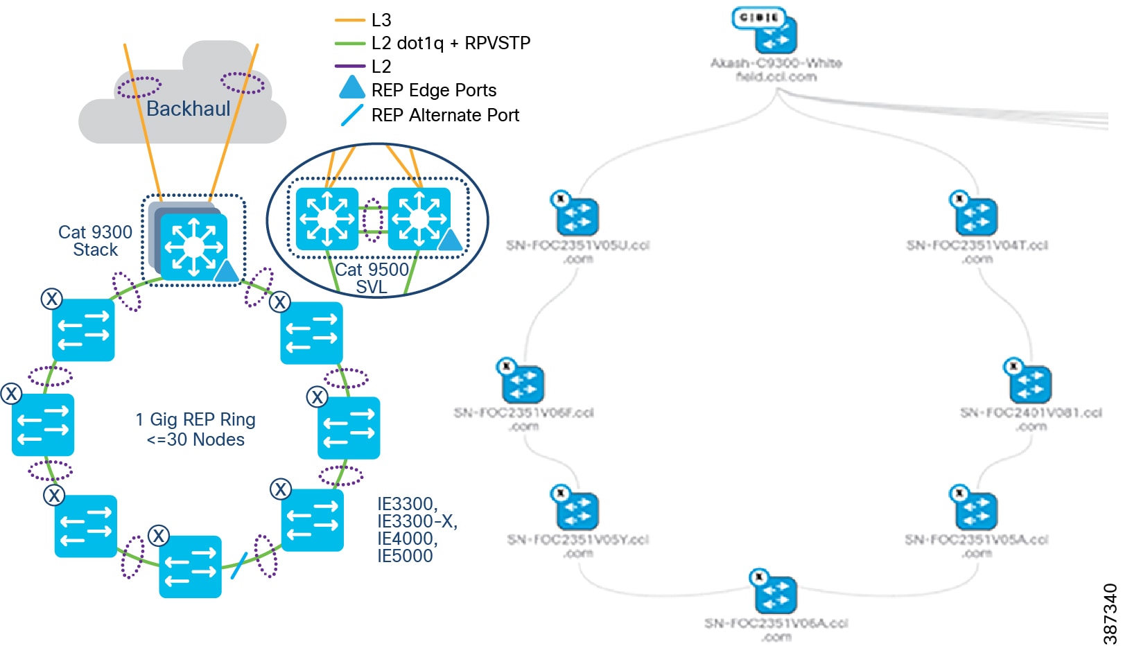
Two uplinks of a Cisco Industrial Ethernet (IE) switch are connected to two access ports on the Fabric Edge (FE), preferably terminating on two different switch members of the FiaB stack. The two ports that the Cisco IE switch is connected to are auto configured into a port channel by the Cisco DNA Center and marked as EN ports, or PEN ports for IE3400 switches. The Cisco DNA Center also configures these ports as trunk ports allowing all VLANs. Based on the VLAN of the traffic entering the EN port of the FE, it is tagged with appropriate Security Group Tag (SGT) and Virtual Network (VN), and the segmentation policy is applied.
Note: CURWB Radios that connect to the Ethernet access ring can often require a maximum transmission unit (MTU) greater than 1500 bytes. Therefore, configuring a system-wide MTU of 2000 bytes on all IE switches in the ring to accommodate to higher MTU packets is recommended.
The REP primary and secondary edge ports are configured on FiaB on a stack of C9300 Series switches or C9500 switches StackWise Virtual, forming a closed ring of Cisco Industrial Ethernet (IE) switches. This allows detection of any REP segment failure, including the uplink ports of ENs or PENs on the FiaB Stack or C9500 StackWise Virtual, and initiates convergence. Provisioning REP as a closed ring topology in CCI as shown in CCI Access Network REP Ring Topology for network high availability and improved traffic convergence in case of link failures within the REP segment is recommended.
Figure 18 CCI Access Network REP Ring Topology
Provisioning the REP Ring using Cisco DNA Center REP Workflow
Cisco DNA Center release 2.2.3.3 REP configuration workflow feature extends the cascading of multiple EN or PEN switches in a ring topology. The ring topology is set up though physical connection between two ENs or PENs and switches that are onboarded into the Cisco DNA Center fabric through Plug and Play (PnP). The Cisco DNA Center REP automation workflow feature considers FiaB as a REP edge device to form a REP ring from two ENs or PENs connected to the same Fabric Edge or FiaB.
Cisco DNA Center REP ring configuration Prerequisites shows the prerequisites for the REP ring configuration using Cisco DNA Center REP automation feature.
Figure 19 Cisco DNA Center REP ring configuration Prerequisites
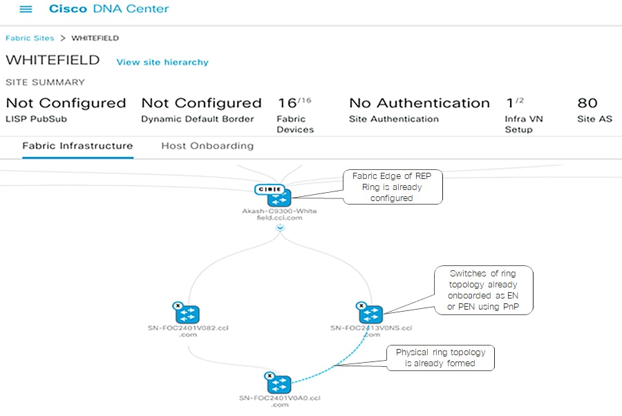
The detailed step-by-step instructions to configure REP ring using workflow for the Extended or Policy Extended Nodes ring are discussed in the CCI Implementation Guide.
REP Ring Design Considerations, Limitations, and Restrictions
- Only new REP ring (Greenfield) deployments are supported; I.e, an existing REP ring topology if any (may have been configured using Day N templates) in a CCI PoP cannot migrated to a new REP ring configuration using Cisco DNA Center REP automation feature.
- Considering the Fabric Edge (FE) as the root bridge, then a maximum of 20 nodes including FE is supported without tuning the STP timer. To support 30 nodes in a REP ring, configure the REP ring by changing the STP maximum-age timer value to 40 on the STP root bridge before starting the REP configuration workflow.
- A mix of EN and PEN in a daisy chain or REP ring is not supported.
- To insert or delete an EN or PEN Node in the existing REP Ring delete the REP Ring. A switch connected in a REP Ring cannot be deleted from the fabric until the REP Ring that it is a part of it is deleted.
- Multiple rings within a REP ring is not supported; a ring of rings is not supported.
Provisioning the REP Ring using Cisco DNA Center REP Workflow
Cisco DNA Center release 2.2.3.3 REP configuration workflow feature extends the cascading of multiple EN or PEN switches in a ring topology. The ring topology is set up though physical connection between two ENs or PENs and switches that are onboarded into the Cisco DNA Center fabric through Plug and Play (PnP). The Cisco DNA Center REP automation workflow feature considers FiaB as a REP edge device to form a REP ring from two ENs or PENs connected to the same Fabric Edge or FiaB.
Cisco DNA Center REP ring configuration Prerequisites shows the prerequisites for the REP ring configuration using Cisco DNA Center REP automation feature.
Figure 20 Cisco DNA Center REP ring configuration Prerequisites
The detailed step-by-step instructions to configure REP ring using workflow for the Extended or Policy Extended Nodes ring are discussed in the CCI Implementation Guide.
REP Ring Design Considerations, Limitations, and Restrictions
- Only new REP ring (Greenfield) deployments are supported; I.e, an existing REP ring topology if any (may have been configured using Day N templates) in a CCI PoP cannot migrated to a new REP ring configuration using Cisco DNA Center REP automation feature.
- Considering the Fabric Edge (FE) as the root bridge, then a maximum of 20 nodes including FE is supported without tuning the STP timer. To support 30 nodes in a REP ring, configure the REP ring by changing the STP maximum-age timer value to 40 on the STP root bridge before starting the REP configuration workflow.
- A mix of EN and PEN in a daisy chain or REP ring is not supported.
- To insert or delete an EN or PEN Node in the existing REP Ring delete the REP Ring. A switch connected in a REP Ring cannot be deleted from the fabric until the REP Ring that it is a part of it is deleted.
- Multiple rings within a REP ring is not supported; a ring of rings is not supported.
Note: Cisco DNA Center REP Ring Automation is a limited available feature. Please contact Cisco Sales team before using this feature in CCI deployments.
Policy Extended Node Ring
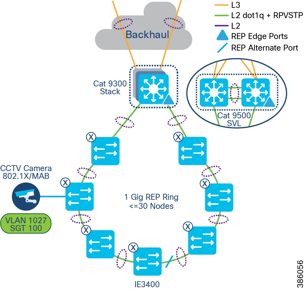
Additionally, an Ethernet access ring network consisting of all IE3400 Series switches only can be formed as a Policy Extended Node ring, as shown in CCl Policy Extended Node REP Ring Topology.
Endpoints or hosts onboarded in the Policy Extended Node in the ring will have the right VLAN and SGT tag attributes downloaded from ISE to enforce communication policy based on SGT for improved endpoint and ring security. Also, the Policy Extended Node in the ring support 802.1X/MAB based closed authentication for endpoints.
Figure 21 CCl Policy Extended Node REP Ring Topology
Cisco DNA Center REP workflow can be used to discover and provision all PEN Cisco Industrial Ethernet (IE) switches in the access ring. Refer to the section Provisioning the REP Ring using Cisco DNA Center REP Workflow. The detailed step-by-step instructions to configure daisy-chained ring topology and REP using workflow for the Extended Nodes or Policy Extended Node ring are covered in the CCI Implementation Guide.
Note: REP Fast feature is capable of reducing L2 convergence times, however REP Fast is only supported on IE3x00 and ESS3300 switches (not IE4000, IE5000 nor Catalyst 9000), and is also not supported on Port Channel interfaces – because of this, REP Fast is not suitable for inclusion in the CCI CVD. For more information on REP Fast please see https://www.cisco.com/c/en/us/products/collateral/switches/industrial-ethernet-switches/white-paper-c11-743432.html
Ten Gigabit Ethernet Access Ring Design
Cisco Catalyst IE3300 Rugged Series switches deliver up to 10 Gigabit high-speed Ethernet connectivity in a compact form factor. They are designed for a wide range of industrial applications where hardened products are required. The platform is built to withstand harsh environments in manufacturing, energy, transportation, mining, smart cities, and oil and gas. The modular design of the Cisco Catalyst IE3300 Rugged Series offers the flexibility to expand to up to 26 ports of Gigabit Ethernet or up to 24 ports of Gigabit Ethernet and 2 ports of 10 Gigabit (10G) Ethernet with a range of expansion module options.
The Cisco IE3300 10G series with expansion module is rated 480W for IEEE® 802.3af / 802.3at / 802.3bt (type 3 & type 4), shared across up to 24 ports. It is ideal for connecting high power over Ethernet (PoE) end devices such as PTZ IP cameras, phones, high power 802.11ac Wave 2 / 802.11ax wireless access points, sensors, and other devices.
Cisco IE330010Gig Series (aka IE3300-X) switches are available in the following SKUs:
- IE3300-8T2X-E/A – a Non-PoE switch SKU with either Network Essentials (E) or Network Advantage (A) license option
- IE3300-8U2X-E/A - a PoE switch (480W maximum PoE budget) SKU with either Network Essentials (E) or Network Advantage (A) license option
Refer to the following link for more details on Cisco Catalyst IE3300 Rugged Series switches.
https://www.cisco.com/c/en/us/products/collateral/switches/catalyst-ie3300-rugged-series/catalyst-ie3300-rugged-series-ds.html
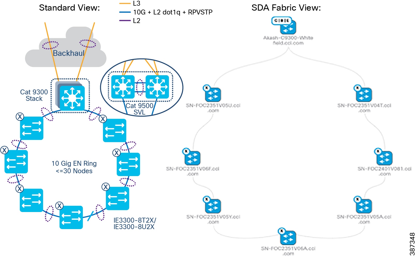
In CCI, an Ethernet access ring in a point of presence (PoP) can deliver 10 Gigabit speed with up to 18 switches in a spanning tree protocol (STP) ring using the maximum-age timer default value 20 and fabric-in-a-box (FiaB) as the STP root bridge. Changing the maximum-age timer value to 30 allows a ring configuration of 30 switches. Refer to the Daisy chaining Linear and Star Topology Design for more details on the ring size. 10Gigabit Ethernet Access ring shows a 10Gigabit Ethernet access ring topology in a CCI PoP providing high-speed network connectivity to endpoints in the network. The ring is formed with one 10Gig interface in the Port Channel (PC) supporting one 10G interface for uplink PC and another 10G interface for downlink PC from each industrial Ethernet (IE) switch in the ring. Although the Cisco Catalyst IE5000 Series classic switches provide a 10Gig access ring, a IE3300-X 10Gig series switches for high-speed ring is recommended because it also supports the following advantages.
- The latest Catalyst-based IOX-XE software with edge-compute capabilities for hosting a Cyber Vision Network sensor application
- Higher PoE ports density and PoE power budget for access points and endpoints
–![]() IE-3300-8U2X Base module support - 8 x 1Gigabit Ethernet copper ports (up to 60W)
IE-3300-8U2X Base module support - 8 x 1Gigabit Ethernet copper ports (up to 60W)
–![]() IEM-3300-4MU Expansion module - 4 x Multigigabit Copper Ports operating in either 1G or 2.5G speed 4-pair Power-over-Ethernet (4PPoE) Type 4 (up to 90W).
IEM-3300-4MU Expansion module - 4 x Multigigabit Copper Ports operating in either 1G or 2.5G speed 4-pair Power-over-Ethernet (4PPoE) Type 4 (up to 90W).
Figure 22 10Gigabit Ethernet Access ring
CCI Remote Point-of-Presence Design
This chapter covers CCI Remote Point-of-Presence (RPoP) design considerations to extend CCI macro segmentation and multiservice network capabilities to remote sites along with RPoP network, management and services high availability.
This chapter includes the following major topics:
- Remote Point-of-Presence Gateways
- Remote Point-of-Presence Design Considerations
- RPoP High Availability Design
- RPoP DSL Backhaul Design
- Remote PoP Gateways Management
Remote Point-of-Presence Gateways
An RPoP is a Connected Grid Router (CGR) or Cisco Industrial Router (IR) and is typically connected to the Public Internet via a cellular connection, although any suitable connection can be used (such as xDSL or Ethernet), over which FlexVPN secure tunnels are established to the CCI HE in the DMZ.
This section covers the CCI Remote PoP gateway(s) that aggregates CCI services at RPoP(s) and extends the CCI multiservice network to RPoP endpoints. The RPoP router may provide enough local LAN connectivity, or an additional Cisco Industrial Ethernet (IE) switch may be required.
Cisco IR1101 as RPoP Gateway
Cisco IR1101 Integrated Services Router is a modular and ruggedized platform designed for remote asset management across multiple industrial vertical markets. As part of the CCI solution, the IR1101 can play the role of a CCI RPoP gateway aggregating remote site (RPoP) endpoints/assets and services and extending the CCI multiservice network to the RPoP along with network macro-segmentation.
For more details, refer to the IR1101 Industrial Integrated Services Router Hardware Installation Guide at the following URL:
As shown in An Example Multiservice RPoPRPoP Macro-Segmentation Design , IR1101 is designed as a modular platform for supporting expansion modules with edge compute. IR1101 supports a variety of communication interfaces such as four FE ports, one combo WAN port, RS232 Serial port, and LTE modules. The cellular module is pluggable and a dual SIM card and IPv6 LTE data connection are supported. SCADA Raw sockets and protocol translation features are available.
The IR1101 provides investment protection. The base module of IR1101 provides a modular pluggable slot for inserting the pluggable LTE module (or) storage module. The expansion module, on the other hand, also comes with a modular pluggable slot for inserting the pluggable LTE module. Overall, two pluggable LTE modules could be inserted on IR1101 (with an expansion module), thus enabling cellular backhaul redundancy with Dual LTE deployments.
Using the expansion module, an additional fiber (SFP) port, an additional LTE port and an SSD local storage for applications could be added to the capability of IR1101.
For more details on IR1101 base and expansion modules, refer the following URL:
Cisco IR1800 as RPoP Gateway
Cisco Catalyst IR1800 Rugged Series Routers are secure, high-performance, 5G routers in a modular design that support private LTE, Wi-Fi6 and Gigabit Ethernet. In CCI, IR1800 series routers can be used as RPoP gateways providing better response time, and increase cost efficiencies with secure, reliable access to real-time data for various industry vertical use cases.
Ultra-modular design supports evolving business and technical needs, protecting your investment.
Supports multiple different modules, including public or private 4G/LTE and 5G, Wi-Fi 6, FirstNet certified public safety LTE, SSD, and advanced GNSS, thus providing a high level of flexibility to choose the desired configuration to suit individual deployments.
Refer to the following URL for more details on Cisco Catalyst IR1800 Rugged Series Routers:
- https://www.cisco.com/c/en/us/products/collateral/routers/catalyst-ir1800-rugged-series-routers/nb-06-cat-ir1800-rugged-ser-rout-ds-cte-en.html
Note: Cisco IR-1800 platform cannot be managed by IoTOD as it is not supported. It can only be managed by Cisco DNA Center.
Cisco CGR1240 as RPoP Gateway
The CGR 1000 Series Routers are ruggedized, modular platforms on which utilities and other industrial customers can build a highly secure, reliable, and scalable communication infrastructure. They support a variety of communications interfaces, such as Ethernet, serial, cellular, Radio-Frequency (RF) mesh, and Power Line Communications (PLC). In CCI, CGR1240 router can be used as Field Area Router and RPoP gateway with cellular backhaul for providing CR-Mesh access network in CCI PoP and RPoPs.
Refer to the section CR-Mesh Network for more details on CGR1240 in CCI and refer the CCI Remote PoP and IoT Gateways Portfolio Comparison for more details on other IRs as RPoP gateways.
Remote Point-of-Presence Design Considerations
This section covers Cisco IR1101 as Remote PoP gateway design considerations in CCI. It discusses different services that RPoP offers with the capabilities of IR1101 and how the CCI multiservice network with macro-segmentation is extended to RPoP endpoints/assets via the CCI headend (HE) network in the DMZ.
RPoP Multiservice design in IR1101
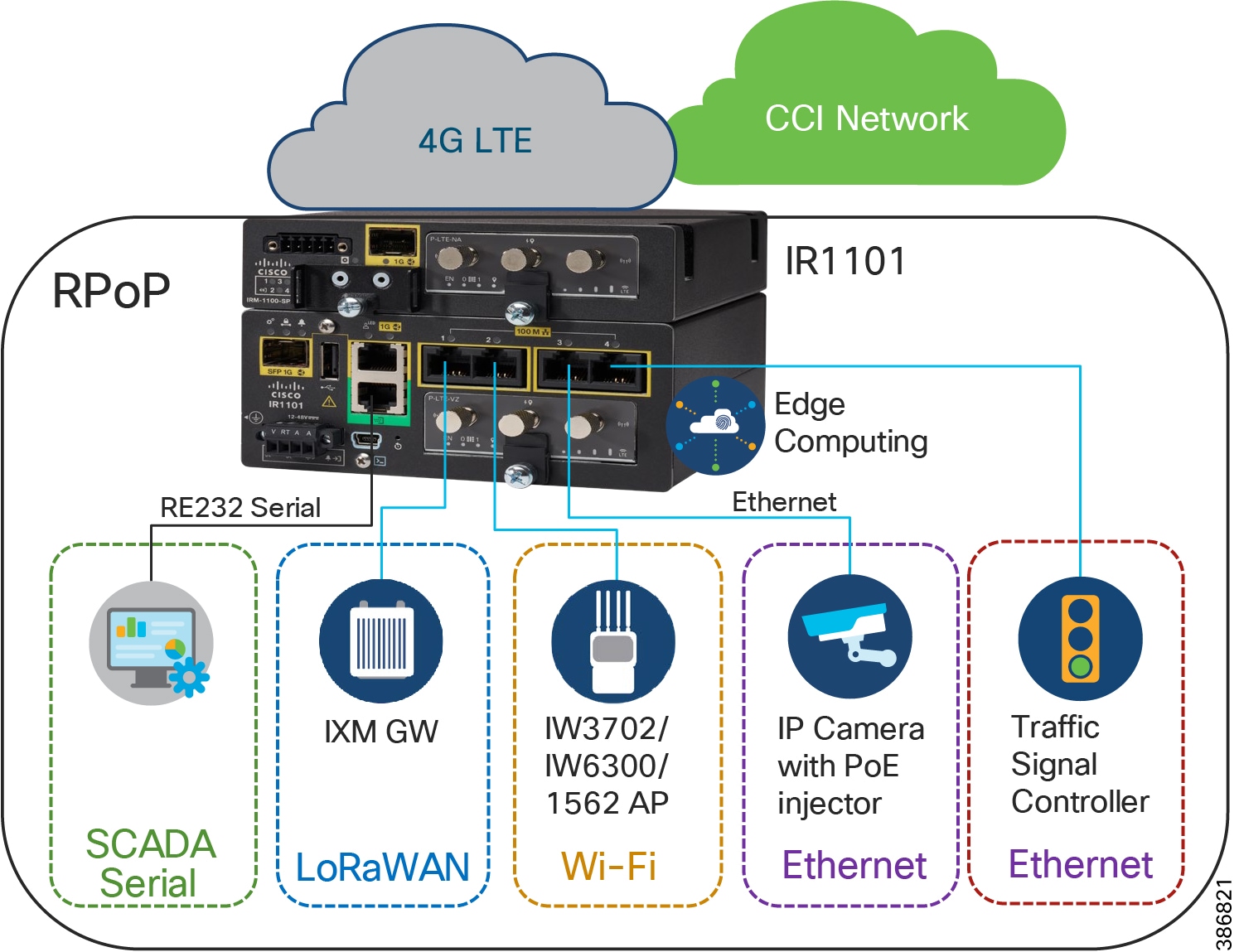
As shown in RPoP Gateway with Macro-Segmentation Design, the IR1101 base module supports four FE (LAN) ports and a RS232 Serial port which helps connect various CCI vertical endpoints. Multi-VRF, VLAN, and VPN features support on IR1101 helps segment the network and services in the CCI RPoP by configuring and maintaining more than one routing and forwarding tables.
An Example Multiservice RPoP shows an IR1101 in the CCI RPoP with the support for the following services:
- Ethernet Connectivity: Separate LAN network Connectivity for CCTV Camera, IXM Gateway (LoRaWAN access network at RPoP), Wi-Fi Access Points (Wi-Fi access network at RPoP) and Traffic Signal Controller in Roadways & Intersection use cases
- SCADA: DNP3 Serial-to-DNP3/IP protocol translation for SCADA Serial RTU devices connectivity at RPoP
- Edge Computing: Analyses the most time-sensitive data at the network edge, close to where it is generated, and enables local actions, independent of backhaul or cloud connectivity. A highly secure, extensible environment for hosting applications ensures authenticity of applications.
A separate LAN network is created on the IR1101 for each of the services in separate Virtual Route Forwarding (VRF) routes. Each LAN network traffic is backhauled via a secure FlexVPN tunnel to the CCI headend network over a Cellular or DSL based public backhaul networks. An Example Multiservice RPoP shows an example multiservice RPoP in CCI.
Figure 23 An Example Multiservice RPoP
RPoP Macro-Segmentation Design
Network segmentation divides a larger network into smaller sub-networks that are isolated from each other for improved security and better access control and monitoring. CCI provides network macro-segmentation using SD-Access which is discussed in the section Security Segmentation Design. CCI RPoP offering multiservice requires each service to be isolated from the other for network security and also provide a CCI RPoP connectivity to rest of CCI network i.e CCI PoP sites and Application Servers in HQ/DC site.
This section discusses the design considerations for macro-segmenting the RPoP network and extend CCI services to RPoPs (IR1101s) connected via public Cellular network (or other backhaul) to the CCI headend (HE) in the DMZ.
Since CCI RPoP traffic can traverse any kind of public WAN, data should be encrypted with standards-based IPSec. This approach is advisable even if the WAN backhaul is a private network. An IPSec VPN can be built between the RPoP Gateway (IR1101) and the HER in the CCI HE. The CCI solution implements a sophisticated key generation and exchange mechanism for both link-layer and network-layer encryption. This significantly simplifies cryptographic key management and ensures that the hub-and-spoke encryption domain not only scales across thousands of field area routers, but also across thousands of RPoP gateways.
IP tunnels are a key capability for all RPoP use cases forwarding various traffic types over the backhaul WAN infrastructure. Various tunneling techniques may be used, but it is important to evaluate the individual technique OS support, performance, and scalability for the RPoP gateway (IR1101) and HER platforms.
The following is tunneling design guidance:
- FlexVPN Tunnel— FlexVPN is a flexible and scalable VPN solution based on IPSec and IKEv2. To secure CCI data communication with the headend across the WAN, FlexVPN is used. IKEv2 prefix injection is used to share tunnel source loopbacks.
- Communication with IR1101 in a RPoP is macro-segmented and securely transported as an overlay traffic through multipoint Generic Routing Encapsulation (mGRE) Tunnels. Next-hop resolution protocol (NHRP) is used to uniquely identify the macro-segments (VNs). It is recommended to combine mGRE, for segmentation, with a FlexVPN tunnel for secure backhaul to the HER.
- Routing for overlay traffic is done via iBGP (VRF Lite) between the RPoP routers and the HER, inside the mGRE; similarly between the HER and FR is done inside p2p GRE.
- RPoP Gateway with Macro-Segmentation Design depicts how CCI services are macro-segmented and extended to RPoPs via the CCI headend (HER) using Point-to-Point FlexVPN (between each IR1101 RPoP and the HER), and Multipoint GRE tunnels (from each IR1101 RPoP over the FlexVPN tunnel to the HER and from there to the Fusion Router).
Figure 24 RPoP Gateway with Macro-Segmentation Design
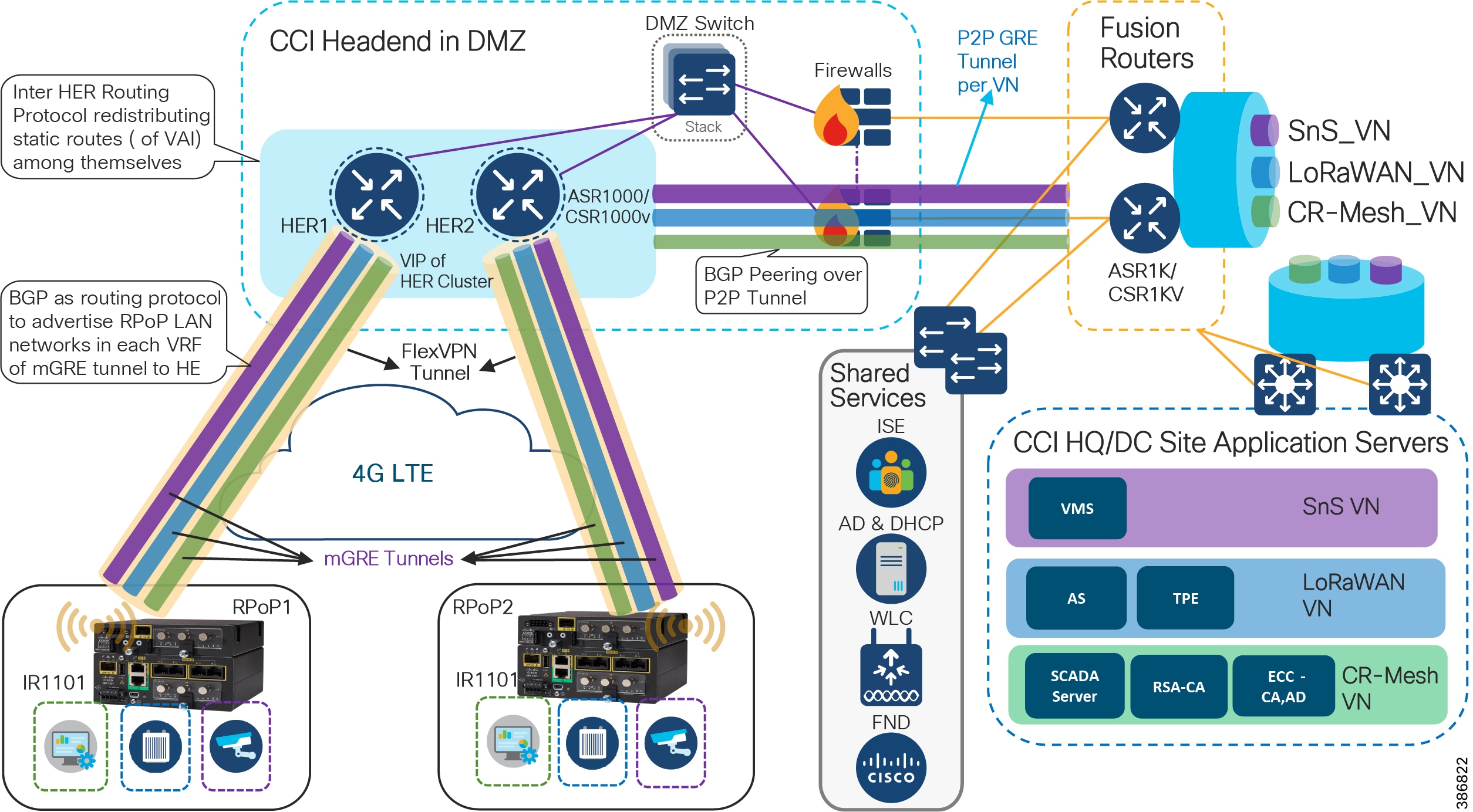
In CCI Headend Router Redundancy :
- CCI HQ/DC Site with Application Servers hosted in each VN for each CCI vertical service. CCI vertical services like Safety and Security (SnS_VN), LoRaWAN access based FlashNet street Lighting (LoRaWAN_VN), CR-Mesh access based Water SCADA (SCADA_VN or CR-Mesh_VN) etc., is macro-segmented in CCI SD-Access fabric with separate routing and forwarding (VRF) tables for each of the services.
- CCI Common Infrastructure or Shared Services consists of Cisco ISE, IoT FND, DHCP & Active Directory (AD) servers and WLC.
- CCI Fusion Routers (FR) connected to HQ/DC site via IP-Transit extends SD-Access fabric overlay VNs/VRFs created in fabric using Cisco DNA Center. FR provides access to non-fabric and shared services in CCI.
- The DMZ network portion of CCI communication headend, which includes:
–![]() A Cluster of ASR1000 Series or CSR1000v routers as Headend Routers (aka Hub Router for IP Tunnels)
A Cluster of ASR1000 Series or CSR1000v routers as Headend Routers (aka Hub Router for IP Tunnels)
–![]() Security FirePower/Firewalls in routed mode
Security FirePower/Firewalls in routed mode
- IR1101/IR1800s as Spoke routers in RPoP1 and RPoP2 connected to CCI headend via public cellular (LTE) WAN backhaul network.
Design Considerations
Cisco IR1101/IR1800 routers in CCI RPoP supports multi-VRF, VLAN, and GRE to achieve network segmentation. To build on top of that, access lists and firewall features can be configured on CCI firewalls in the headend to control access to CCI from RPoP gateways/networks.
Tunneling provides a mechanism to transport packets of one protocol within another protocol. Generic Routing Encapsulation (GRE) is a tunneling protocol that provides a simple generic approach to transport packets of one protocol over another protocol by means of encapsulation.
As shown in CCI Headend Router Redundancy:
- Point-to-Point GRE tunnels are created over L3 (routed) network between Fusion Routers (FR) and HERs for each of the VNs/VRFs in CCI (specifically those needed at an RPoP, although all VNs will be present on the FR). An IP routing protocol peering between FR and HER must be established to exchange CCI SD-Access fabric overlay subnets and routing tables between HER and FR. While any routing protocol may be chosen to exchange IP routing, it is recommended to use BGP to simplify and ease the IP routing configurations in each VRF.
- IP routes among HER cluster nodes are advertised using a routing protocol redistributing static and Virtual Access Interface (VAI) routes among themselves.
- Each RPoP with IR1101 as a spoke router establishes a FlexVPN tunnel with a HER in CCI headend. This secured FlexVPN tunnel to each RPoP spoke can be established using IoT FND with certificated based authentication similar to CGR1240 FlexVPN tunnel to CCI headend.
- IR1101 with dual LTE modules and dual SIMs could establish two FlexVPN tunnels (one from base module Cellular interface and the other from expansion module cellular interface) to HER Cluster in Active-Active deployment with load-balancing (per-destination based).
- A multipoint GRE (mGRE) overlay tunnel is established for each CCI VN/VRF which needs to be extended to the RPoP. VRF forwarding is enabled on the mGRE tunnel interface on the HER (Hub) and IR1101 (Spoke) in a Hub-and-Spoke deployment. The mGRE overlay tunnel per VRF segments the network for each service in the FlexVPN. Next Hop Resolution Protocol (NHRP) with Next Hop Server (NHS) are configured on each spoke (IR1101) and Hub (HER) with a unique network-id for each VN/VRF.
- An IP routing protocol must be configured between RPoP IR1101 and HER to exchange routing tables between CCI headend and IR1101 in RPoP. BGP is recommended to simplify and ease the IP routing table advertisements in each VRF.
- LAN subnets or VLANs in RPoP VRFs can be redistributed or advertised to HER and then to FR via the routing protocol.
- Once routing information is exchanged between the RPoP and CCI HE, assets/endpoints in the RPoP can communicate with CCI Application Servers or endpoints in CCI PoPs via their respective VN/VRFs and shared services.
Detailed RPoP implementation steps are covered in the Implementation Guide of this CCI CVD.
RPoP High Availability Design
High Availability is achieved by designing redundancy at multiple levels of the CCI solution. This section discusses RPoP high availability design as listed below:
CCI HER Redundancy
Design considerations discussed in this section primary addresses potential failure of the aggregation HER in the CCI headend.
- R1101 acting as FlexVPN spokes and deployed with a single or dual backhaul interface, connect to ASR 1000/CSR1000v aggregation routers in a multi-hub scenario.
- The backhaul interface may be any supported Cisco IOS interface type or cellular and/or Ethernet.
- Two ASR 1000s or more (multi hub) in the same Layer 2 domain can terminate the FlexVPN tunnel setup with a spoke.
- A single FlexVPN tunnel is configured to reach one of the ASR 1000s/CSR1000v routers
- Routing over the FlexVPN tunnel can be IKEv2 prefix injection through IPv4 ACL or dynamic routing, such as BGP (preferred).
Figure 25 CCI Headend Router Redundancy
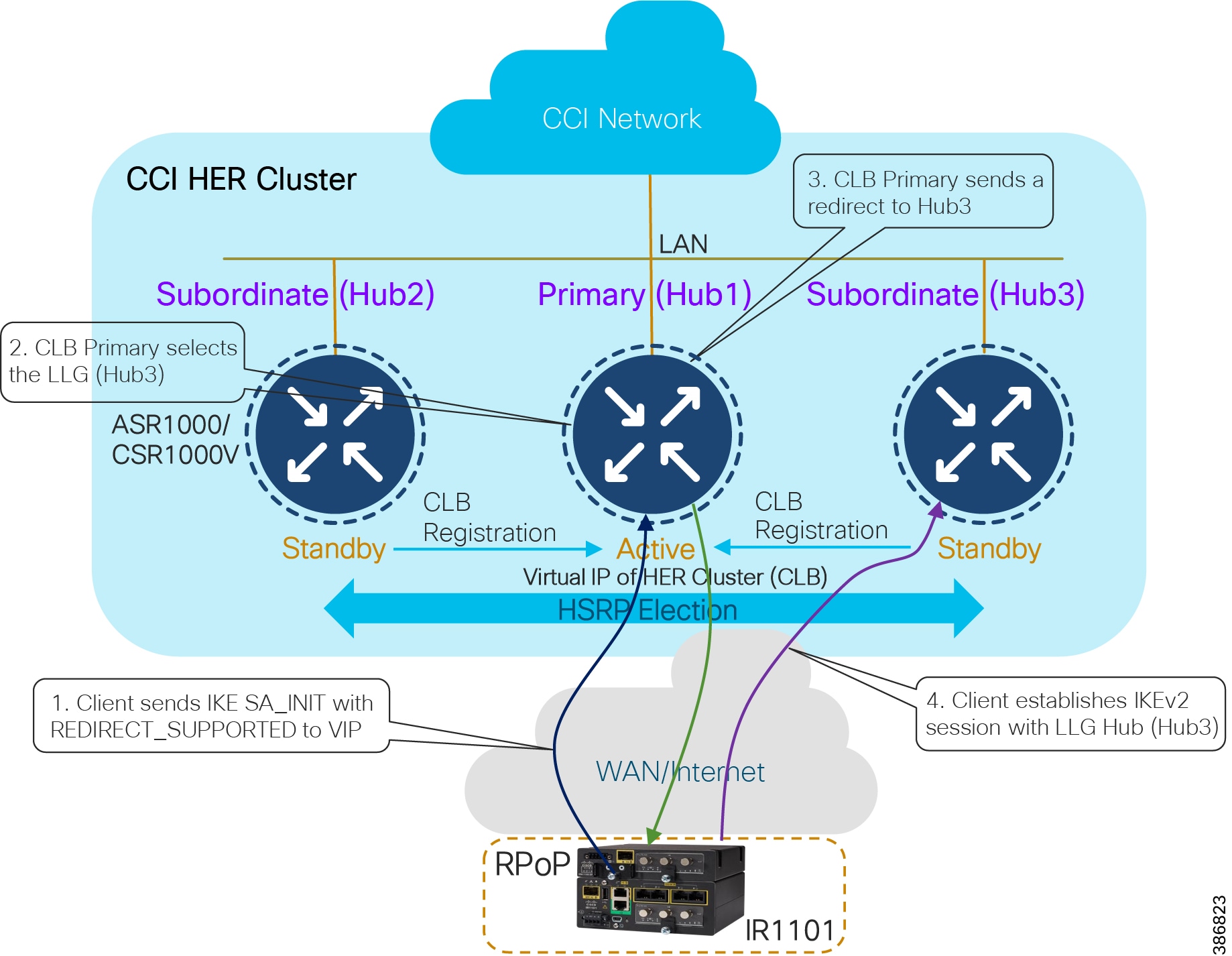
As shown in CCI Headend Router Redundancy, HER redundancy is achieved using the IKEv2 load balancer feature. The IKEv2 Load Balancer support feature on HERs provides a Cluster Load Balancing (CLB) solution by redirecting requests from remote access clients to the Least Loaded Gateway (LLG) in the Hot Standby Router Protocol (HSRP) group or cluster. An HSRP cluster is a group of gateways or FlexVPN servers in a LAN. The CLB solution works with the Internet Key Exchange Version 2 (IKEv2) redirect mechanism defined in RFC 5685 by redirecting requests to the LLG in the HSRP cluster. Failover between HERs will be automatically managed by the IKEv2 load balancer feature.
For more details on IKEv2 Load Balancer feature for FlexVPN, refer to the following URL:
- https://www.cisco.com/c/en/us/td/docs/ios-xml/ios/sec_conn_ike2vpn/configuration/xe-16-5/sec-flex-vpn-xe-16-5-book/sec-cfg-clb-supp.html
ASR 1000s or CSR1000v act as a FlexVPN server. Remote spokes (IR1100) act as FlexVPN clients. The FlexVPN server redirects the requests from the remote spokes to the Least Loaded Gateway (LLG) in the HSRP cluster. An HSRP cluster is a group of FlexVPN servers in a Layer 3 domain. The CLB solution works with the Internet Key Exchange Version 2 (IKEv2) redirect mechanism defined in RFC 5685 by redirecting requests to the LLG in the HSRP cluster.
For the HER configuration, the HSRP and FlexVPN server (IKEv2 profile) must be configured. For the spoke configuration, the FlexVPN client must be configured. The IoT FND NMS should configure HSRP on the HER in addition to the FlexVPN server feature set. In case of any HER failure, tunnels are redirected to other active HER. If the primary fails, one of the subordinates resumes the role of primary.
The Cisco Cloud Services Router 1000V (CSR 1000V) is a router in virtual form factor. It contains features of Cisco IOS XE Software and can run on Cisco Unified Computing System (UCS) servers. The CSR 1000V is intended for deployment across different points in the network where edge routing services are required. Built on the same proven Cisco IOS Software platform that is inside the Cisco Integrated Services Router (ISR) and Aggregation Services Router (ASR) product families, the CSR 1000V also offers router based IPSec VPNs (FlexVPN) features. The CSR1000V software feature set is enabled through licenses and technology pack. Hence, it is suitable for a small HER Cluster deployment where number of IPsec (FlexVPN) tunnels required at the HER cluster is less (1000 tunnels).
In a medium or large deployment, the HER terminates multiple FlexVPN tunnels from multiple RPoP gateways and CGR1240s connected to the CCI Ethernet access rings or RPoPs. Hence, selecting a router platform that supports a large number of IP tunnels is vital to the headend design. It is recommended to use the Cisco ASR 1000 series routers as the HERs considering the potential FlexVPN tunnels scale in CCI.
Refer to the following URL for ASR 1000 HER scaling guidance:
- https://www.cisco.com/c/en/us/td/docs/solutions/Verticals/Distributed-Automation/Secondary-Substation/DG/DA-SS-DG/DA-SS-DG-doc.html#33573
Note: A HER Cluster may consist of > 2 number of routers depending on the FlexVPN tunnels scaling and load-sharing requirements in a deployment. It is recommended to have a minimum of two HERs in a cluster for high availability and load-sharing of RPoP backhaul traffic to the CCI headend.
WAN Backhaul Redundancy
RPoP gateways deployed over a single LTE network are a single point of failure, in the absence of a backup network like a secondary cellular radio interface. IR1101 acting as a RPoP gateway comes with the flexibility to host two LTE network interfaces or one LTE and one Ethernet or DSL enabling WAN Cellular Backhaul redundancy to be achieved.
Active/Active load-sharing WAN backhaul redundancy design uses Dual LTEs (or other supported WAN interfaces) on IR1101 with two-tunnel approach, as shown in RPoP IR1101 Dual-LTE: Load Sharing Scenario.
Figure 26 RPoP IR1101 Dual-LTE: Load Sharing Scenario
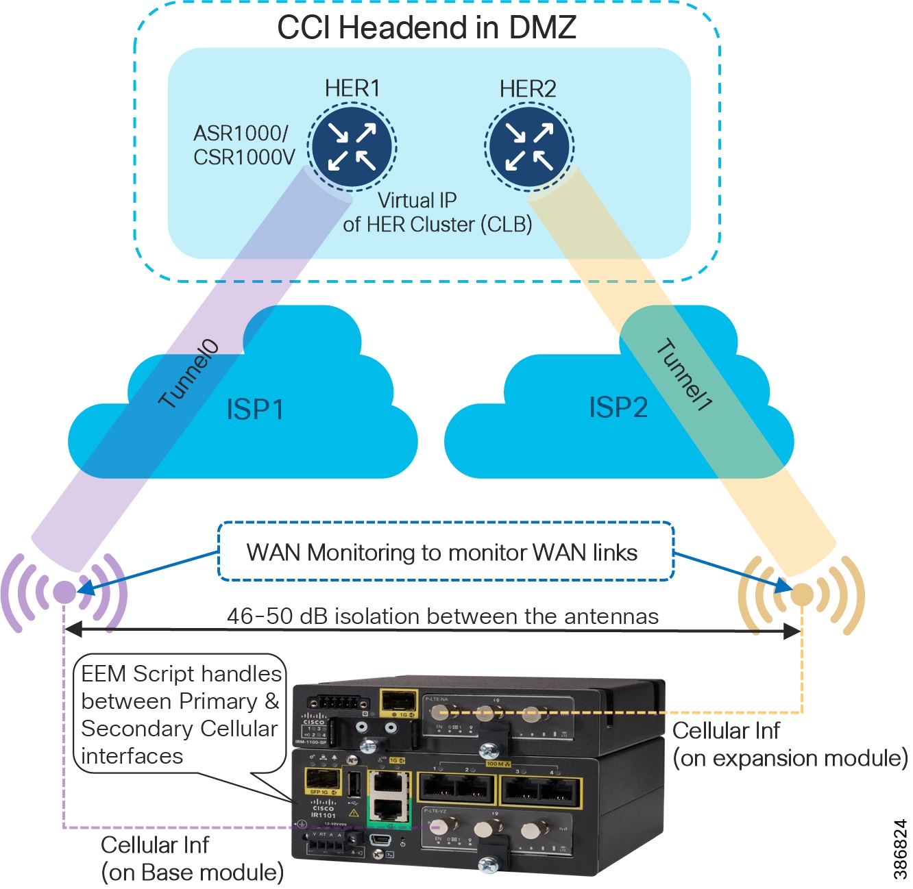
- Two tunnels from the RPoP gateways terminates on two different HER clusters at the headend. In normal operational scenarios, both the tunnels would be UP and would be performing load-sharing of traffic across primary and secondary LTE modules. Load balancing is per-destination based.
- Should any of the WAN links (primary/secondary), only the corresponding Tunnel goes down. The other LTE module (and its corresponding Tunnel) would still be UP and keeps forwarding the traffic. For example, if the Cellular interface on the expansion module goes down, only Tunnel1 goes down. Hence, Tunnel0 can still forward the traffic.
In RPoP IR1101 Dual-LTE: Load Sharing Scenario, if the primary radio on base module fails, it could be a failure related to the radio or service provider. An Embedded Event Manager (EEM) script detects the radio interface failure (or) connectivity failure (read as service provider failure) over the primary radio. Failure of one of the radios detected by EEM script, leaving only one active radio and its corresponding tunnel for traffic forwarding.
Refer to the following URL for RPoP IR1101 WAN redundancy design considerations for Dual LTEs with Active-Active and Active-Standby tunnels from RPoP gateways to headend.
Combined Redundancy
It is possible to combine both HER and Backhaul redundancy. HER redundancy will allow a single HER cluster to be resilient, to load-balance RPoP routers across the cluster and also to serve RPoPs at the HE in the case of one or more HER failures. WAN Backhaul redundancy allows a given RPoP to have two WAN links, and for them to operate in an active-active model, where both links are active and passing traffic, and in the event of a failure of one of these links all the traffic is sent via the remaining link; however to do this those two WAN links must terminate on different HER clusters. These HER clusters could be at the same physical location, or different locations.
RPoP DSL Backhaul Design
Digital Subscriber Line (DSL) is a modem technology that uses existing telephone lines to transport high-bandwidth data, such as multimedia and video, to service subscribers. DSL provides dedicated, point-to-point, public network access. This DSL connection is typically between a network service provider (NSP) central office and the customer site, or on local loops created either within buildings or campuses.
DSL delivers high-bandwidth data rates to geographically dispersed locations with relatively minor changes to the existing telecommunications infrastructure. This advantage is of significant interest to implementers and service providers (SPs). Today the focus on DSL is addressing appropriate connectivity requirements in Europe, the UK, and Australia where SPs are phasing out legacy Public Switched Telephone Network (PSTN) lines and offering DSL.
DSL is used for SCADA and telemetry in remote locations where there is either no Wi-Fi LTE/Ethernet connectivity, or legacy PSTN connections are being migrated to DSL. The term “xDSL” represents several similar and competing forms of DSL, including Asymmetric DSL (ADSL) and Very Highspeed DSL (VDSL).
The Cisco Industrial Routing Platform IR1101 adds DSL capability by using a Small Form-factor Pluggable (SFP) network interface module. The IR1101 platform with DSL SFP supports ADSL2 (Annex A, L), ADSL2+ (Annex A), and VDSL2+ (Annex A, B).
A remote point of presence (RPoP) with IR1101 as the remote gateway can be connected to a Connected Communities Infrastructure (CCI) headend network. The connection is made over a Service Provider’s DSL backhaul network using a DSL SFP on the IR1101. The DSL network provided by a SP typically includes a Digital Subscriber Line Access Multiplexer (DSLAM) and a Broadband Remote Access Server (B-RAS) at the Central Office. The Service Provider’s DSL network design is beyond the scope of this CCI design guide.
DSLAM
A Digital Subscriber Line Access Multiplexer (DSLAM) is a network device located at the SP central office or exchange that connects multiple subscriber DSL interfaces to a high-speed digital communication channel using multiplexing techniques. Depending on the device architecture and setup, a DSLAM aggregates the DSL lines using Asynchronous Transfer Mode (ATM), fame relay, and/or Internet Protocol network creating an IP-DSLAM.
Broadband Remote Access Server (B-RAS)
The Broadband Remote Access Server (B-RAS) is a key component of DSL broadband access networks that serves as an aggregation point for subscriber traffic. This subscriber traffic uses IP, PPP, and ATM and includes session termination (PPPoX, RFC 1483) and subscriber management functions such as authentication, authorization, accounting (AAA), and IP address assignment.
DSL Architecture and Components shows the high-level DSL architecture and its components.
Figure 27 DSL Architecture and Components
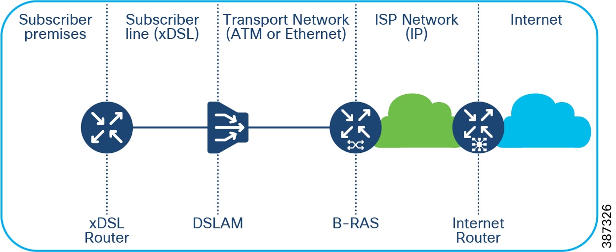
The next section discusses RPoP DSL design considerations using IR1101 with DSL SFP acting as a xDSL router supporting ADSL2/2+ and VDSL2 variants.
ADSL2/ADSL2+
Asymmetric DSL (ADSL) allows more bandwidth for downstream than upstream data flow. This asymmetric technology combined with always-on access makes Asymmetric DSL ideal for users who typically download much more data than they send.
Design considerations for ADSL include:
- The maximum upstream data rate is 1 Mbps, and the maximum downstream data rate is 20 Mbps, both supported by ADSL2/2+
- The ADSL2/ADSL2+ backhaul can support SCADA, LoRaWAN Gateway aggregation, and Roadways Vertical services in CCI
- The recommended distance between the remote PoP location and the central office is 5.5KM or less for ADSL2/2+
- A special QoS design is required for ADSL backhaul because of the considerable difference in uplink and downlink bandwidth.
VDSL2
VDSL2 is a digital subscriber line (DSL) technology providing data transmission faster than an asymmetric digital subscriber line (ADSL).
Design considerations for VDSL2 include:
- VDSL2 supports data rates of up to 200Mbps downstream and 100Mbps upstream
- VDSL2 DSL backhaul is the preferred choice for Cities Safety and Security and Wi-Fi vertical services
- The distance between the RPoP and the central office for VDSL2 backhaul must be 500 meters or less
- The transportation of vertical services and the application requirement must be understood to position the ADSL2/2+ and VDSL2 variant in a CCI RPoP
Refer to the following URL for more details on the ADSL2/2+ and VDSL2 features and support for the IR1101 DSL SFP: https://www.cisco.com/c/en/us/td/docs/routers/access/1101/software/configuration/guide/b_IR1101config/m_configuring_dsl.html#Cisco_Concept.dita_f1099be5-64c9-4592-b44b-6d126e498771
The Cisco IR1101 supports a DSL interface on the base platform that is not supported on the expansion module. The IR1101 DSL router also supports Radius and AAA when authenticating and configuring the DSL users. Layer 3 and Security Features (FlexVPN and others) are supported on the DSL interface. CGNA-based zero touch deployment (ZTD) is supported with FND v4.7 for manging IR1101 router with a DSL interface.
IR1101 DSL SFP ADSL2/2+ and VDSL2 Capability Summary below summarizes the ADSL2/2+ and VDSL2 Transmission mode features supported by IR1101 DSL SFP.
Figure 28 IR1101 DSL SFP ADSL2/2+ and VDSL2 Capability Summary
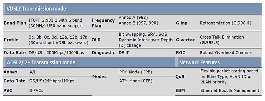
Note: The Cisco IOS-XE release 17.5.1 includes support for the Annex-J and ADSL2+ J configurations in the controller interface. ADSL2 J is not supported in release17.5.1.
CCI RPoP connectivity to CCI Headend via DSL backhaul shows a CCI RPoP IR1101 connection to the Headend via DSL backhaul.
Figure 29 CCI RPoP connectivity to CCI Headend via DSL backhaul
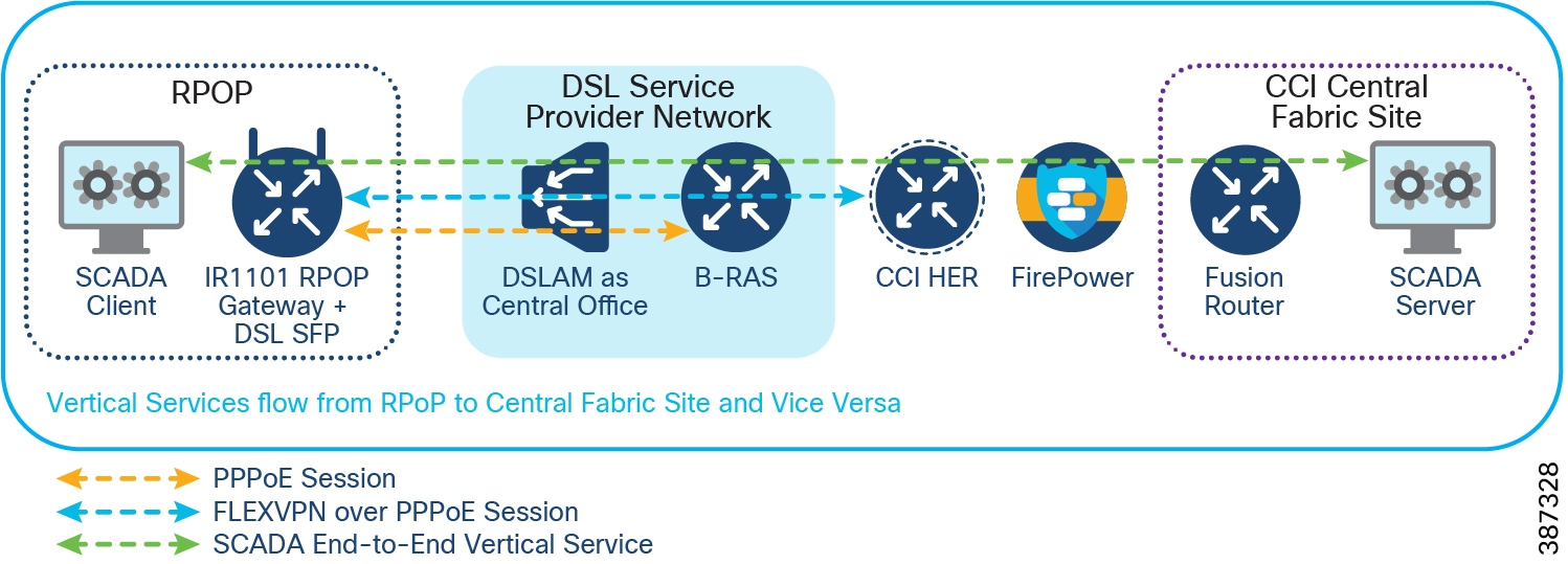
- A Point-to-Point Protocol over Ethernet (PPPoE) session is terminated at the Service Provider B-RAS. The Service Provider’s B-RAS provides DHCP and NAT Services for the IR1101.
- A Dialer interface is used as a FlexVPN tunnel source interface. The FlexVPN tunnel is formed between the RPoP gateway and the CCI HER over a PPPoE session.
- Vertical Services traffic is encrypted. The CCI Remote PoP network segmentation design (mGRE per VRF) applies. Refer to the Remote Point-of-Presence Design Considerations in this document.
CCI RPoP connectivity to the Internet via DSL backhaul shows a CCI RPoP IR1101 connection to the Headend via DSL backhaul with Internet access for subscribers in the RPoP.
Figure 30 CCI RPoP connectivity to the Internet via DSL backhaul
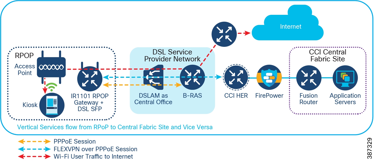
The DSL Service Provider configures Internet access for DSL subscribers (RPoP IR1101) using a B-RAS router.
Remote PoP Gateways Management
This section describes management design using the IR1101 and IR1800 Series routers as RPoP gateways in CCI RPoPs.
Note: In this section the terms IR1101, IR1800, and RPoP gateway may be used interchangeably to refer to the remote site router in CCI.
The CCI design provides two options for managing the RPoP gateways and IE switch connected behind gateways, its edge applications, and service functions. Following two management platforms helps achieve RPoP management:
- Cisco DNA Center – An on-premise network management and assurance application that is part of the CCI common infrastructure known as Shared Services. This software platform manages the CCI network core, distribution and access IE switches, and security policy configurations for IoT applications in the CCI network.
- Cisco IoT Operations Dashboard (IoTOD) - A cloud-based dashboard that empowers both operations teams and IT support staff to deploy and monitor networking devices, industrial assets, and the streams of data they produce at massive scale.
An RPoP gateway in CCI can be managed by Cisco IoTOD (Option A1) and Cisco DNA Center (Option B1), as shown in CCI RPoP Management Options. An IE switch can be connected behind an RPoP gateway to extend the Ethernet access for multiple endpoints in the RPoP. The IE switch connected to the RPoP gateway is managed either manually using the CLI option (Option A2) for an IoTOD-managed RPoP or by using the Cisco DNA Center for the RPoP managed by Cisco DNA Center (Option B2).
Figure 31 CCI RPoP Management Options
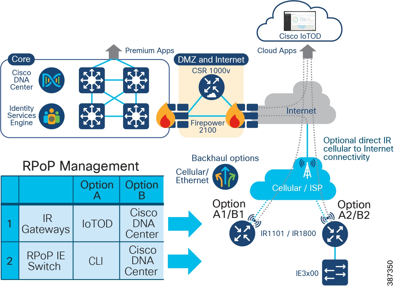
Depending on the customer deployment of management application and services needed for the RPoP gateway, either the Cisco IoT Operations Dashboard or Cisco DNA Center or both can be used to manage the CCI RPoPs.
Cisco DNA Center for RPoP Management
A CCI RPoP with either a IR1101 or IR1800 Series gateway can be managed using the Cisco DNA Center in a CCI Shared Services network. As shown in RPoP Management Design using Cisco DNA Center, a separate Management VRF is created with Management VLANs to configure the IR1101 or IR1800 with the management IP address. A gateway configuration also includes the SNMP and SSH command line interface (CLI) configuration for its successful addition to the Cisco DNA Center inventory.
Prerequisites for adding a RPoP gateway to Cisco DNA Center:
The RPoP gateway is staged with a base configuration and is connected to the Cisco DNA Center in the shared services network through a management virtual network (VN). The base configuration includes FlexVPN and a multipoint generic encapsulation (mGRE) tunnel configuration for Management VN. This staging configuration can be deployed using the gateway WebUI tool.
Refer to the following URL for more details on WebUI:
https://www.cisco.com/c/en/us/td/docs/routers/access/1101/software/configuration/guide/b_IR1101config/b_IR1101config_chapter_010111.html
Refer to the section “RPoP Macro-Segmentation Design ”, for more details on RPoP FlexVPN with mGRE design.
- For management of Remote gateways using Cisco DNA Center, a separate virtual routing and forwarding (VRF) network named Management VN is configured on a headend router (HER) and fusion router, which can reach the shared services.
- A FlexVPN tunnel and an mGRE tunnel over FlexVPN are established between the RPoP gateway and the CCI HER. This enables the IP reachability between the gateway and the Cisco DNA Center over Management VRF.
- The SSH CLI and SNMP configurations are added on the RPoP gateway for discovery by the Cisco DNA Center.
The Cisco DNA Center device discovery feature discovers the RPoP gateway using its IP address and adds it into the inventory. The RPoP gateway configuration, discovery, and management using Cisco DNA Center are described in detail in the CCI Implementation Guide.
Figure 32 RPoP Management Design using Cisco DNA Center
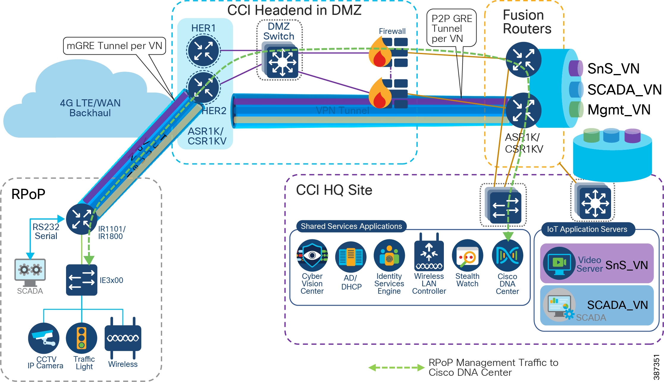
RPoP Gateway Network Management and Service using Cisco DNA Center
The following are the key IoT gateway management services that can be performed from Cisco DNA Center.
- RPoP gateway Assurance - Remote health monitoring of RPoP gateways (Device Health) from CCI central or HQ site
- Centralized Infrastructure Services – Network Infrastructure services like IP address assignment using DHCP, and authentication and authorization of endpoints in an RPoP using the Cisco Identity Service Engine (ISE) are enabled centrally at the shared services network.
- Remote Gateway configuration – Configuring the gateway using Cisco DNA Center Day-N templates. CLIs supported by RPoP gateways can be pushed to the gateway using the Day-N templates feature of the Cisco DNA Center. For example, configurations to add a new VN/VRF for extending a CCI vertical service to an RPoP can be pushed to the gateway using templates. Services include adding VRF, mGRE tunnel configuration for vertical services, and others, to the HER.
- As shown in Cisco DNA Center Inventory Topology View of a CCI RPoP, the Day-N template feature in the Cisco DNA Center is used to add the following vertical services configuration in an RPoP. Up to 10 VRFs can be configured in an RPoP for different vertical services in CCI for Cities and Roadways use case deployments.
–![]() Safety and Security VRF (SnS_VN) for City Safety
Safety and Security VRF (SnS_VN) for City Safety
–![]() SCADA VRF for Water SCADA use cases
SCADA VRF for Water SCADA use cases
–![]() Lighting VRF for City Street lighting
Lighting VRF for City Street lighting
–![]() Traffic VRF for Roadway and Intersection endpoints and applications
Traffic VRF for Roadway and Intersection endpoints and applications
- Gateway upgrade management - Managing and upgrading the gateway software image can be accomplished using Cisco DNA Center software image management (SWIM) feature.
- Dynamic Segmentation of endpoints in the RPoP Gateway Fast Ethernet (FE)/Gigabit Ethernet port can be configured to connect to an IE switch which extends network access for multiple IoT endpoints in RPoP, as shown in CCI RPoP Management Options. FE ports can also be configured to dynamically authenticate using 802.1X or MAC address bypass (MAB) and authorize the endpoints such as the CCTV Camera, traffic controller, and other devices. Segments at the endpoint in a particular VLAN can be authenticated based on authorization using Cisco ISE at CCI HQ site. This is referred to as macro segmentation.
IE switch Management in Cisco DNA Center managed RPoP
An RPoP gateway supports up to four FE port for remote IoT endpoints connectivity in CCI. To connect more than four endpoints in the RPoP, a Cisco IE switch (IE3x00/IE4000 Series) can be connected to an RPoP gateway, as shown in RPoP Management Design using Cisco DNA Center. The IE switch connected behind the RPoP gateway can also be managed using Cisco DNA Center, which is managing the RPoP gateway.
IE switch in the RPoP is manually added to Cisco DNA Center application inventory via its discovery process. The procedure and prerequisites to discover the RPoP IE switch in Cisco DNA Center is same as manually discovery of any network device in Cisco DNA Center. However, there are few pre-staging configurations needed on the IE switch as mentioned below for its successful discovery at Cisco DNA Center.
Prerequisites for adding RPoP IE switch into Cisco DNA Center:
- For the management of Remote IE switch using Cisco DNA Center, the Management VLAN from the RPoP gateway Management VN/VRF is configured in the IE switch. An SVI with IP address in Management VLAN is configured in the IE switch.
- A FlexVPN tunnel is established between RPoP gateway (IR1101 or IR1800) and CCI HER. IP reachability is available between IE switch and Cisco DNA Center via Management VLAN.
- SSH CLI and SNMP configurations are added on the IE switch (IR1101 or IR1800) to be discovered by Cisco DNA Center.
Cisco DNA Center device discovery feature discovers the IE switch behind the RPoP gateway using its IP address and adds the switch into its inventory., as shown in Cisco DNA Center Inventory Topology View of a CCI RPoP.
Cisco DNA Center Inventory Topology View of a CCI RPoP shows an IR1101 as RPoP gateway and IE3400 switch connected to it, is discovered and added into Cisco DNA Center inventory.
Figure 33 Cisco DNA Center Inventory Topology View of a CCI RPoP
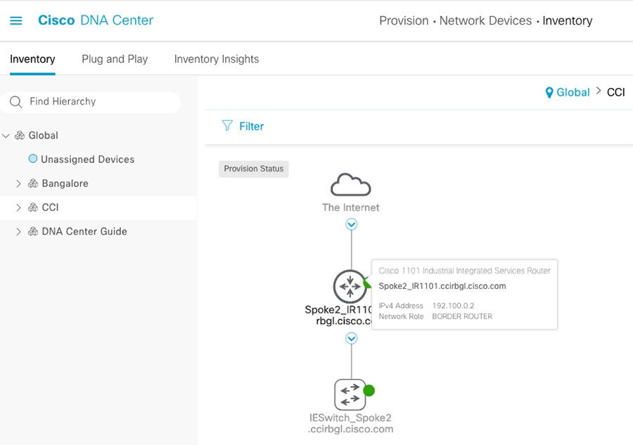
IE Switch Network Management and Serviceability in RPoP
Once the IE switch in an RPoP is discovered and added into Cisco DNA Center inventory, some of the important management services of the switch must be considered. The following are the key switch management services that can be performed from Cisco DNA Center.
- Device Assurance - Remote health monitoring of the IE switch (Device Health) from CCI central/HQ site using Cisco DNA Center
- Remote switch configuration – Configuring the switch using Cisco DNA Center Day-N templates. For example, the switchport 802.1X or MAB authentication and policy configuration can be pushed to the switch via templates.
- IE switch upgrade management – Switch software image management and upgrading of the switch image, can be done using Cisco DNA Center SWIM feature.
- Dynamic Segmentation of endpoints in RPoP– Switch ports can be configured to dynamically authenticate (using 802.1X or MAB) and authorize the endpoints connected to it (e.g, CCTV Camera, traffic controller etc.,).Also, segments the endpoint in a particular VLAN (macro-segmentation) based on authorization done using Cisco ISE at CCI HQ site.
Cisco IoT Operations Dashboard for RPoP Management
Cisco IoT Operations Dashboard is a cloud-based dashboard that empowers both operations teams and IT support staff to deploy, monitor, and gain insights from networking devices, industrial assets, and the streams of data they produce, at massive scale. With one comprehensive view of all their connected industrial assets, operations teams can uncover valuable insights that help them run more efficiently and provide operational continuity.
Cisco IoT Operations Dashboard enables connectivity for industrial assets using Cisco industrial networking devices, including the Cisco IR1101, IR1800, IR829, IR809, IR807 industrial routers and wireless gateways for LoRaWAN. With Zero-Touch Deployment (ZTD) and resilient remote management of Cisco devices, the cloud-based IoT Operations Dashboard enables faster setup of challenging IoT networks.
In CCI, Cisco IoT Operations Dashboard (IoTOD) on cloud can be used as RPoP gateways management platform to perform following key gateway management functions:
- Zero-Touch Provisioning 7(ZTP) of RPoP gateways using cellular or Ethernet backhaul
- Ability to schedule firmware upgrades over the air or via a wired connection for gateways
- OT user-centric form-based UI workflow to onboard
- RPoP gateways for mass field deployment
- Real-time gateway visibility, insights, and location tracking
- Intuitive map-based monitoring dashboard and troubleshooting of RPoP gateways
- Certificate-based secure authentication between RPoP gateway and cloud dashboard
- Managing groups /configuration templates and gateway Operation Logs
An RPoP gateway can be onboarded in CCI network using ZTP over cellular backhaul. ZTP allows gateways to be on-boarded and configured automatically without human intervention, such as deploying a trained technician on-site, thus eliminating most of the manual labour involved in adding gateways to a network.
ZTP allows the RPoP gateway to be installed directly into a CCI remote site, and for that physical installation to be the last hands-on involvement. When the gateway is powered-on, it requests an IP address via DHCP from either an CCI DHCP server for a fixed connection or cellular provider(s) for mobile connections.
Cisco PnP Solution Components
- Cisco Smart Account – Manages Smart Licenses of the RPoP gateways through a Smart Account. A Cisco Smart Account is required to use Cisco IoT PnP. Contact Cisco Sales team or account team to ask to be added as an administrator if your organization already has an account.
- PnP Controller Profile - The PnP Controller Profile specifies the Cisco IoT host (i.e., Cisco IoTOD in this case) that provisions your gateways for use with Cisco IoTOD. The profile is selected when adding a device to Cisco PnP. PnP controller profile is available in PnP Connect in your Smart Account.
- PnP Connect Portal - PnP Connect provides Cisco IoT security certificate configured in your PnP Controller Profile and redirect the RPoP gateway to the Cisco IoT PnP Server.
- PnP Server – Onboards the RPoP gateway in to network and pushes IoT device specific configuration to the gateway
RPoP gateway ZTP process and PnP Solution Components illustrates ZTP process of an IR1101/IR1800 as RPoP gateway in CCI using IoTOD and Cisco Plug-and-Play solution components.
Figure 34 RPoP gateway ZTP process and PnP Solution Components
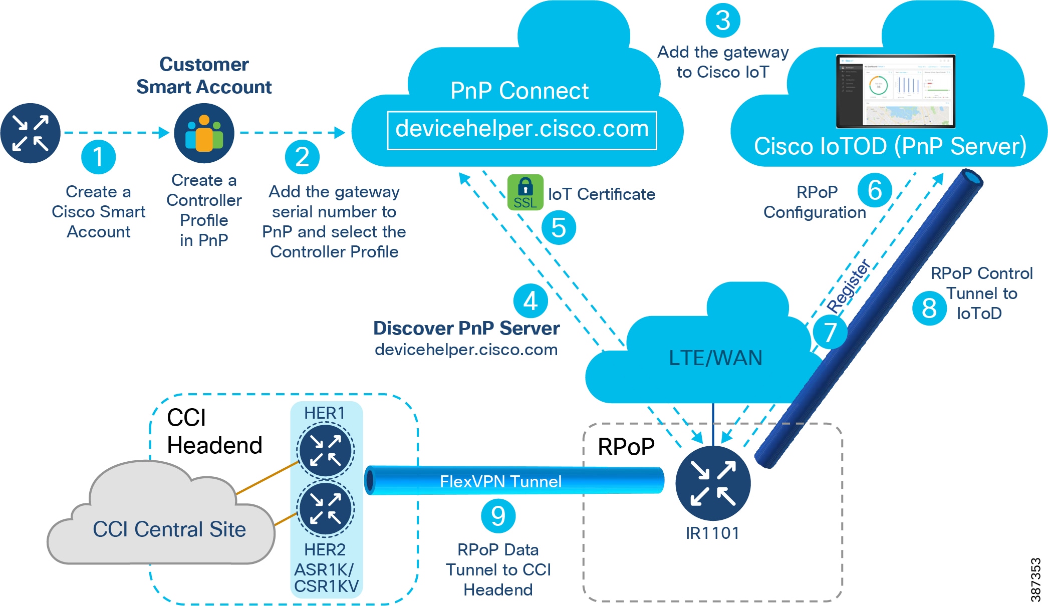
1.![]() Create a Cisco Smart Account. A Cisco Smart Account is required to use Cisco IoT PnP. Customer should contact Cisco Sales/Account teams to create a Smart Account as part of gateway purchase. Create a “PnP Controller Profile” that specifies the Cisco IoTOD that provisions your gateway for use with Cisco IoTOD.
Create a Cisco Smart Account. A Cisco Smart Account is required to use Cisco IoT PnP. Customer should contact Cisco Sales/Account teams to create a Smart Account as part of gateway purchase. Create a “PnP Controller Profile” that specifies the Cisco IoTOD that provisions your gateway for use with Cisco IoTOD.
2.![]() Enter the gateway serial number using the Controller Profile you just created.
Enter the gateway serial number using the Controller Profile you just created.
3.![]() Add the gateway to Cisco IoTOD. The config for the selected template is loaded when the gateway is added to the network.
Add the gateway to Cisco IoTOD. The config for the selected template is loaded when the gateway is added to the network.
Note: You can add the gateway to Cisco IoT either before or after connecting it to the network.
4.![]() Connect the gateway to your network and power it on. The gateway will auto-discover PnP Connect with "devicehelper.cisco.com”.
Connect the gateway to your network and power it on. The gateway will auto-discover PnP Connect with "devicehelper.cisco.com”.
5.![]() PnP Connect will push the Cisco IoTOD security certificate configured in your PnP Controller Profile and redirects the gateway to the Cisco IoTOD PnP Server.
PnP Connect will push the Cisco IoTOD security certificate configured in your PnP Controller Profile and redirects the gateway to the Cisco IoTOD PnP Server.
6.![]() The Cisco IoTOD PnP Server will push the correct RPoP gateway base configuration to the gateway.
The Cisco IoTOD PnP Server will push the correct RPoP gateway base configuration to the gateway.
–![]() The edge device will call home to Cisco IoT and wait to be claimed.
The edge device will call home to Cisco IoT and wait to be claimed.
–![]() The Cisco IoTOD template configuration is applied when the gateway is discovered on the network.
The Cisco IoTOD template configuration is applied when the gateway is discovered on the network.
7.![]() Gateway registers with Cisco IoTOD on cloud.
Gateway registers with Cisco IoTOD on cloud.
8.![]() A control tunnel is formed between IoTOD and the gateway as part of base configuration.
A control tunnel is formed between IoTOD and the gateway as part of base configuration.
9.![]() Additional CCI specific configuration is pushed to the gateway via the template associated with the gateway at IoTOD. This CCI specific RPoP configuration for the gateway includes FlexVPN data tunnel configuration to connect RPoP gateway to CCI headend router. This RPoP configuration in the template may also include mGRE overlay tunnel configuration needed on the gateway for CCI vertical service.
Additional CCI specific configuration is pushed to the gateway via the template associated with the gateway at IoTOD. This CCI specific RPoP configuration for the gateway includes FlexVPN data tunnel configuration to connect RPoP gateway to CCI headend router. This RPoP configuration in the template may also include mGRE overlay tunnel configuration needed on the gateway for CCI vertical service.
This completes ZTP process and the gateway has transitioned to “Unheard —> Bootstrapping—> Up (Green)” state during this onboarding process.
Refer to the following URL for more step-by-step details on gateway onboarding using PnP on Cisco IoTOD.
https://developer.cisco.com/docs/iotod/#!zero-touch-provisioning
Once the gateway is successfully added to IoTOD with FlexVPN configuration to CCI HER, the CCI vertical services specific configurations (e.g, mGRE tunnel and VRF configuration needed for each of the VN like SCADA_VN, SnS_VN etc.,) can be configured on the gateway using different templates in IoTOD. For example, Template 1 configures only the RPoP gateway with base configuration, FlexVPN tunnel and mGRE over FlexVPN tunnel needed for deploying the gateway with a management VRF and VRFs for two vertical services. Template 2 can be created to add a new VRF in the RPoP for a newly added vertical service in CCI.
Refer the CCI Implementation Guide for more details on example templates and configurations tested in RPoP.
Cisco IoTOD supports various gateway management functions such as dashboard monitoring, gateway software image upgrade, IOx application management, troubleshooting gateways with Operation Logs, etc.
Refer to the following URL for more details on management features supported in IoTOD:
https://developer.cisco.com/docs/iotod/#!zero-touch-provisioning/management
The IE switch connected behind an RPoP gateway managed by IoTOD, should be managed out-of-band, as IoTOD does not support IE switches management. As shown in RPoP Managed by IoTOD, the IE3x00 switch connected behind the gateway should be configured with SSH and CLI credentials to remotely access the switch for configuration and image management from a CCI HQ Site.
Figure 35 RPoP Managed by IoTOD
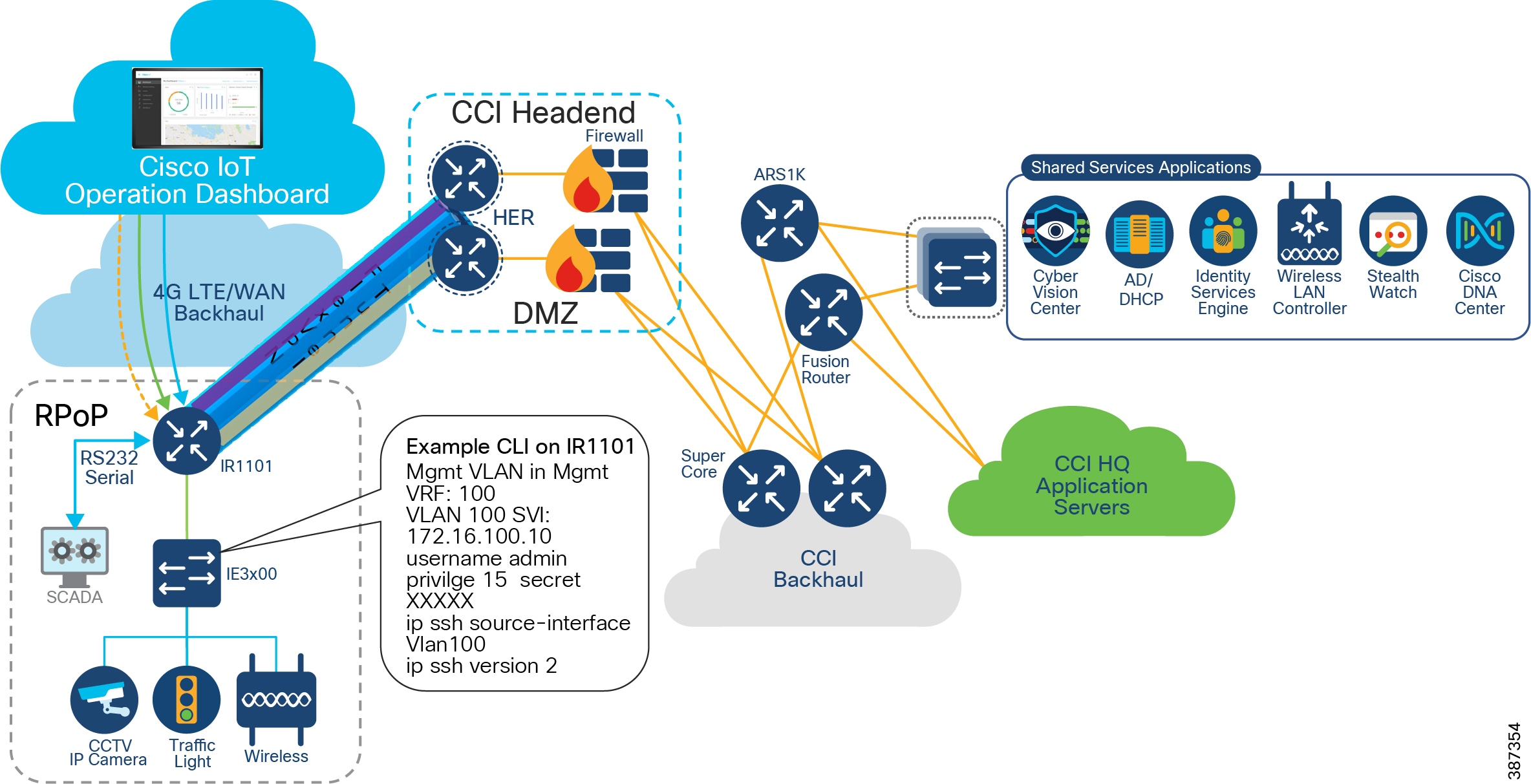
The CCI RPoP deployment and example configurations are covered in detail, in the implementation guide of this CVD.
Ultra Reliable Wireless Backhaul
The Cisco Ultra Reliable Wireless Backhaul (CURWB) product line provides numerous benefits and features in the outdoor IoT space. They can provide network connectivity in a fixed infrastructure environment with point-to-point, point-to-multipoint, or bridge mode. They can also provide seamless network connectivity in a mobile environment such as a moving train.
What enables this flexible wireless deployment is a customized MPLS implementation that ensures an unbroken communication path which overcomes the limits of standard wireless protocols. This implementation acts as an overlay on the CCI network. It enables data throughput of up to 500Mbps at up to 225MPH (360 KMH) with optimal wireless conditions in a mobile environment. In a fixed infrastructure, it enables a flexible and resilient point-to-multipoint mesh network.
MPLS relies on label identifiers, rather than the network destination address as in traditional IP routing, to determine the sequence of nodes traversed to reach the end of the path. An MPLS-enabled device is also called a Label Switched Router (LSR). A sequence of LSR nodes configured to deliver packets from the ingress to the egress using label switching is denoted as a Label Switched Path (LSP), or “tunnel”. LSRs on the border of an MPLS-enabled network and / or other traditional IP-based devices are also called a Label Edge Router (LER).
Solution Components
The following components are used in the CCI Rail trackside solution as part of the wireless infrastructure, in addition to the components which are already part of the main CCI infrastructure.
Below is a brief description of terminologies referred to in this document:
Mesh Point – A Mesh Point primarily serves to swap MPLS labels as traffic ingresses and egresses. This means all Mesh Points function as an LSR and act as a relay between a mobile radio or a host device and a Mesh End. When a Mesh Point is connected to the wired network, it is operating in infrastructure mode. A Mesh Point can also operate in wireless only mode to act as a wireless relay.
Mesh End – Whether used for mobility or fixed infrastructure, the Mesh End performs the same basic functionality. It is the logical demarcation point between Mesh Points and the L3 IP network. Using the MPLS terminology described before, all Mesh Ends function as LSRs and LERs. A Mesh End must have a wired connection and it must be in the same broadcast domain as the Mesh Points.
In a fixed infrastructure, the Mesh End enables communication between the hosts or switch behind the Mesh Point and the rest of the L3 IP network.
A FM 3500 is suitable to serve as a Mesh End if the expected aggregated traffic does not exceed 500 Mbps. The FM 1000 is the recommended Mesh End unit when the aggregate traffic will not exceed 1 Gbps.
Global Gateway – A global gateway is a special type of Mesh End that enables seamless roaming between different Layer 3 domains. It resides in the datacenter as described above. A global gateway serves to anchor numerous Mesh Ends in different broadcast domains and provide seamless roaming across them. This is achieved by building L2TP tunnels between the Global Gateway and all Mesh End devices.
This fast MPLS label swapping between the above nodes along with L2TP tunnels between the Mesh Ends and Global Gateway enable seamless roaming at high speed and high throughput.
A Global Gateway is not used in a fixed infrastructure environment.
Plug-ins – CURWB features are dependent on software licenses called Plug-ins. There are plug-ins for maximum throughput, security, and other network features. The high availability feature, called TITAN and explained later in this document, also requires the appropriate plug-in.
Resiliency (TITAN)
TITAN is a software feature for fail-over technology that constantly tracks link status and network performance of a pair of Mesh Ends or Global Gateways configured in an active-standby role. In case of any failure of the primary unit, traffic is rerouted to the redundant secondary unit. The pair is configured with a single virtual IP address to appear as one unit.
Under the TITAN configuration, the pair of devices will fall into a primary or secondary role (based on the unit Mesh ID) and issue keepalives between them in a pre-configured interval (typically between 50 ms and 200 ms). The secondary unit becomes the new primary when it has not received a keep-alive message within the pre-defined interval.
Simultaneously, the new primary issues commands to all other CURWB devices in the domain to inform them of the change while updating its own tables and sending gratuitous ARPs out its ethernet port to ensure new traffic will be forwarded properly to the new primary. This feature allows failure detection and recovery in 500ms.
Quality of Service Support
The CURWB forwarding engine supports DiffServ like end-to-end QoS treatment to user traffic. The implementation leverages MPLS technology to bring traffic-engineering features to wireless mesh networks.
The QoS implementation supports 8 priority levels (0 to 7 with 0 being the lowest priority and 7 being the highest) as below.
Refer to RFC 791 and RFC 2474 for more detail.
Figure 36 Priority Value in DSCP/TOS Field
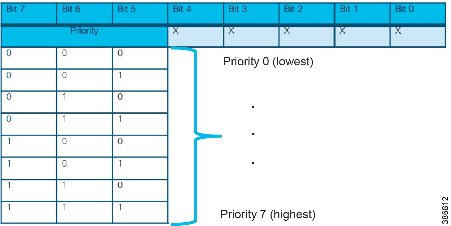
When an IP packet first enters the mesh network at an ingress CURWB unit, the TOS field of the IP header is inspected and a priority class using the Class Selector is assigned in the MPLS EXP bits. The class number is the first 3 most significant bits (bit 5 – 7) of the TOS field.
The priority class is then preserved through the end-to-end path to the egress CURWB unit.
For packets being transmitted over the wireless, the 8 priority levels are further mapped into four classes, each corresponding to a specific set of MAC transmission parameters
|
|
|
|---|---|
As the labels are swapped between Mesh Points, the EXP bits are copied to each label. When the MPLS packet reaches the Mesh End, the TOS bits are copied into the L2TP IP Header as a Class Selector value. At the Global Gateway, the L2TP header and MPLS label are removed and the packet original DSCP/TOS value is retained.
Network Provisioning and Monitoring
Configuration Tools (Configurator and RACER)
The Configurator is a web-based configuration software that resides on the CURWB device locally. A user can connect to the device L3 IP address configured from the Virtual Network IP Pool to view this interface.
RACER is a cloud-based configuration portal that can be accessed through the Internet. Using the RACER portal, a CURWB device reachable from the RACER portal can be configured remotely. The RACER portal also supports different permissions based on the user role. An administrator would be able to edit a device config or assign devices to other users and a viewer would only be able to view a device configuration. The devices must also be entered into the RACER portal before the device can have a successful connection. These features ensure that rogue devices and rogue users cannot make changes to the devices.
A CURWB device has to be configured with some basic settings before it can be part of the wireless network. If a new unit is being configured for the first time or has been reset to factory default configuration for any reason, the unit will enter Provisioning Mode. This mode allows setting of the unit initial configuration.
If the unit is in Provisioning Mode, it will try to connect to the Internet using Dynamic Host Configuration Protocol (DHCP):
- The device will try and connect to partners.fluidmesh.com on port 443
- If the unit successfully connects to the Internet, the unit can be configured by using RACER or by using the local Configurator tool.
- If the unit fails to connect to the Internet, the unit must be configured using the local Configurator interface.
If the unit is not able to connect to the Internet, it will revert back to a Fallback state and its setting will become the factory default setting with IP address to 192.168.0.10/255.255.255.0.
In this state, RACER can still be used in an offline mode. All the devices are entered into the RACER portal and the configuration built for each one. The configurations for all the devices can then be exported as a single file.
Using the Configurator page on the device, the RACER section gives the option to upload a RACER configuration file. The device will choose the correct config from the file and apply the configuration.
Because these configurations can be done ahead of time in the RACER portal, this is the recommended option if Internet access to the device is undesirable. The devices can be pre-staged before deployment or a user with a laptop can upload the config to the device at the deployment site. After the device is fully configured and has reachability within the VN, further config changes can be made using RACER offline, but from a centralized location.
MONITOR
MONITOR is a centralized radio network diagnostic and monitoring tool. It is used to:
- Monitor the real-time condition of CURWB networks.
- Generate statistics from network history.
- Verify that device configuration settings are optimal for current network conditions.
- Receive event loggings for diagnostic and repair purposes and generate alerts if network-related faults arise.
- Analyze network data with the goal of increasing system uptime and maintaining optimum network performance.
- Generate and back up network statistics databases for future reference.
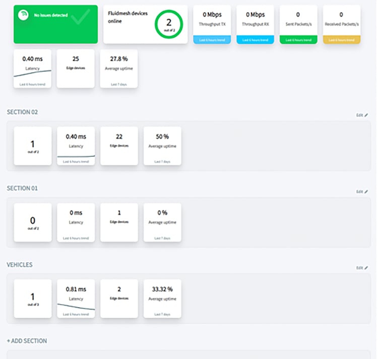
Fixed Infrastructure and CCI Network Integration
Backhaul
In the backhaul network, the radios are used to provide connectivity from a fabric site to the headquarters network. In this capacity, they are in the role of underlay. Because this link acts as an invisible wire, it can also support SD Transit. When considering the IP addressing, they can be consolidated to a separate IP space for consistent management or they can share the IP space of the attached infrastructure switches to minimize how many subnets are used. When Monitor is being used, it is important to ensure IP reachability to all the radio subnets. Additionally, when configuring the radios to be on a separate management network, the VLAN plugin must be installed. This enables a separate management VLAN as well as a different native VLAN if desired.
Due to the nature of wireless connections, there are extra considerations and compromises that must be accounted for in deploying a wireless backhaul. The maximum throughput achievable on these wireless links is 500Mbps, which may be further reduced depending on the RF environment or the number of spoke radios in a point to multipoint environment.
To mitigate this throughput limitation and to provide resiliency in the connection, multiple radios can be configured as separate paths to the radio headend. Each radio path is configured as a separate IP path and when using an IGP with load balancing, traffic between the fabric border and core network will be balanced over the available radio links.
Another restriction due to limitations in the radio hardware is the MTU on the link. The current recommendation for the Ethernet backhaul is an MTU of at least 9100B. The wireless radios can support an MTU of 2044B, which includes all headers and trailers.
See CURWB Backhaul for an example wireless backhaul network.
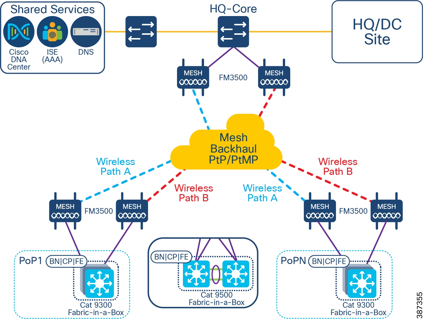
Access
CURWB can also be used at the fabric edge to provide connectivity between the extended node switches. This can be advantageous when a number of road intersections need fabric connectivity but there is no wired connection available.
Because of the nature of wireless connections, the switches can be arranged in various topology shapes such as a star, a linear daisy chain, or a ring. To work with the Extended Node onboarding process from Cisco DNAC, certain restrictions in the wireless deployment are necessary. When a new switch, which is extended node capable, is connected to an existing fabric switch, it will initiate the PNP process which will configure, among other things, a port channel on both switches. This implies the connection is a point-to-point link. Therefore, using the point to multipoint functionality of the wireless radios to onboard multiple switches to a single switch port will not be successful. Each switch port must only connect to one other switch port on an extended node.
To create a star topology using wireless links, for instance, each port must connect to a separate radio. Because the radios will only be used in pairs between switches, it is recommended to configure them in Bridge mode instead of Mesh End/Mesh Point mode. This configuration eliminates the overhead of MPLS present in Mesh mode.
When creating a ring topology using the CURWB radios, special consideration is needed for ensuring the stability of the ring. Because the connection to the radio is 1 Gbps and depending on how many links are wireless in the ring, there could be a situation where the throughput on the ring exceeds the bandwidth of the wireless link. This could manifest itself as some control plane packets, like REP, being dropped because of congestion and the ring being destabilized. To mitigate against this scenario, it is recommended to configure QoS shapers on each IE4000 port facing the CURWB radio at a rate below the maximum observed throughput of the link. If two wired daisy chains are joined with a single wireless link, it is also recommended to configure the wireless link as an alternate REP port so the primary path is using the wired links.
The switches are also further restricted to operate as Extended Nodes only as opposed to Policy Extended Nodes. When configured as Policy Extended Nodes, the switch trunk port configuration enables TrustSec to support policy enforcement. The wireless radios positioned between the two switches will pass the traffic from one side to the other, however, they do not understand TrustSec or the SGTs. Any traffic destined specifically to the radios will not be understood and therefore dropped. There can be no communication or management of these radios. Extended Nodes do not enable TrustSec on the connecting trunk links and therefore do not add SGTs to the traffic.
When considering the IP addressing, if the radios are being used to bridge the connection between two switches, they should be configured as underlay devices in a separate subnet from the extended node subnet. If MONITOR is being used, this subnet must have IP reachability to it.
When using the CURWB radios to connect hosts to an access switch, configuring these for bridge mode is recommended. In bridge mode, the hosts can onboard with Dot1X/MAB or through the Host Onboarding workflow in Cisco DNAC. In this configuration, the switch ports will be in access mode and therefore the radios should not have the VLAN plugin enabled. This means the bridge radios will need to have IP addresses in the same space as the connected hosts.
See CURWB Access for examples of access networks using CURWB.
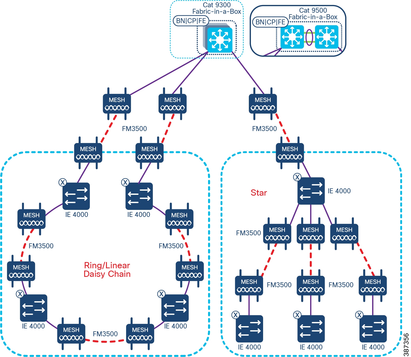
CCI Wi-Fi Access Network
This chapter includes the following topics:
802.11 Wi-Fi is an important access technology for CCI; it supports a number of use-cases, both in terms of outright access and also with Cisco Wi-Fi Mesh, to physically extend the reach and provide a transport path for other devices and access technologies.
CCI covers two different Wi-Fi deployment types: Cisco Unified Wireless Network (CUWN) with Mesh, and SDA Wireless as shown in CCl Policy Extended Node REP Ring Topology. It is not possible to mix both types at a single PoP, however it is possible to have shared SSIDs between say SDA Wireless in PoP1 and CUWN Mesh in PoP2, although it should be noted that there will not be seamless roaming between them, and this scenario is best suited when the neighboring PoPs are sufficiently apart that any Wi-Fi client will not “see” the SSID from both simultaneously.
Figure 40 CUWN and SD Access Wi-Fi Networks
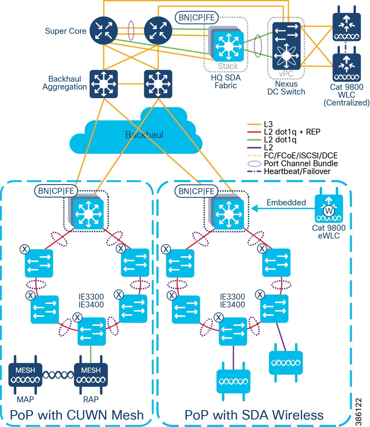
Both deployment types are based on Cisco Wireless Lan Controllers (WLCs) being in control of Cisco Lightweight APs (LWAPP), using the Control and Provisioning of Wireless Access Points (CAPWAP) protocol.
Outdoor (IP67) APs supported and tested as part of CCI are listed and compared in the following table:
WLC scale numbers are shown below, but in addition there are overall DNAC Wi-Fi scale numbers, in terms of total numbers of APs and clients; please refer to: https://www.cisco.com/c/en/us/products/collateral/cloud-systems-management/dna-center/nb-06-dna-center-data-sheet-cte-en.html#CiscoDNACenter1330ApplianceScaleandHardwareSpecifications
Both SDA Wireless and CUWN Mesh will need outdoor antennas to go with the outdoor APs. Cisco has a wide selection of antennas available, with many variants based on frequency, gain, directionality etc.; see https://www.cisco.com/c/dam/en/us/products/collateral/wireless/aironet-antennas-accessories/solution-overview-c22-734002.pdf for more details. In general for SDA Wireless, omni-directional antennas are the usual choice, giving Wi-Fi coverage for clients in all directions from the AP, however in certain scenarios a directional antenna may be preferred. Similarly for CUWN Mesh directional antennas are the norm (certainly for forming the mesh topology itself), and omni-directional antennas may be used for client access. Cisco recommends an RF survey be performed prior to equipment selection and deployment, so that appropriate components can be selected.
Cisco Unified Wireless Network (CUWN) with Mesh
Cisco Unified Wireless Networking is used over-the-top (OTT) of the CCI SDA Fabric; neither the WLCs nor APs are fabric-enabled or aware. CUWN can be used to deliver macro-segmentation, where there is a mapping between Wi-Fi networks (SSIDs) and SDA Virtual Networks (VNs). CUWN is also necessary for Wi-Fi Mesh, which is a topology and technology not currently supported in SDA Wireless.
Figure 41 CUWN Wi-Fi Mesh Design
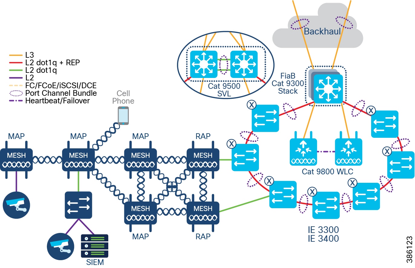
Wi-Fi Mesh is comprised of Root APs (RAPs) and Mesh APs (MAPs). RAPs are the handoff point between wired and wireless Ethernet networks; MAPs connect to RAPs and other MAPs purely over-the-air, in 802.11 RF bands.
For CCI RAPs will (wired) connect to either Fabric Edge ports, or more likely, Extended Node ports.
Three things the Wi-Fi Mesh can be setup to do:
For example: an IP CCTV camera (and the PoE-out capabilities of the AP are important here)
For example: a remote switch, supporting multiple segmented use-cases.
For example: to extend Wi-Fi coverage to areas where there is no wired connectivity
Note : Both RAPs and MAPs can be enabled or disabled for client access.
All the above have slightly different considerations, but in general the design should be for no more than 3 hops, from the RAP to the furthest MAP, and if Wi-Fi client access is enabled for these MAPs it should be done in different spectrum than that used to form the mesh itself; the CCI general recommendation is for 5GHz for mesh backhaul with directional antennas, and optionally for client access too with omnidirectional antennas, with 2.4GHz for client access, (2.4GHz typically increased range over 5GHz, especially outdoors).
Although it is possible to have the Mesh APs self-select 5GHz channels for backhaul, it is the CCI recommendation that channels be manually selected.
For detailed design guidance on Wi-Fi Mesh refer to https://www.cisco.com/c/en/us/td/docs/wireless/controller/8-5/Enterprise-Mobility-8-5-Design-Guide/Enterprise_Mobility_8-5_Deployment_Guide/Chapter-8.html
For Mesh RAPs, or for non-Mesh CUWN APs, FlexConnect mode is used. See https://www.cisco.com/c/en/us/td/docs/wireless/controller/8-5/Enterprise-Mobility-8-5-Design-Guide/Enterprise_Mobility_8-5_Deployment_Guide/ch7_HREA.html for more details on FlexConnect. FlexConnect means that for control traffic CAPWAP is used between the WLC and the AP, but wireless data traffic is broken out onto the wired Ethernet network in the directly connected switch; in this way it can be mapped into the appropriate macro-segments, and have the chance to interact with other Ethernet traffic within a PoP, without having to be tunneled back to the WLC (which would be the default mode: Local mode).
The exception here are any SSID(s) associated with Public Wi-Fi, or some other untrusted Wi-Fi traffic; this traffic is tunneled back to the WLC inside CAPWAP packets, where it can be dealt with appropriately.
Figure 42 CUWN Wi-Fi Mesh with FlexConnect
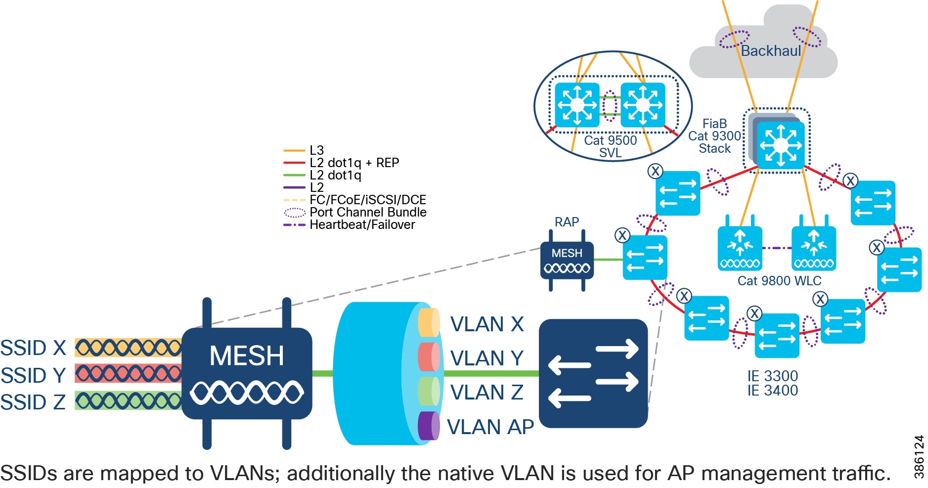
Centralized WLC deployment
Locating a HA WLC pair in the Shared Services segment means it is centralized and can shared across all PoPs. Consequently centralized WLC is typically a larger appliance:
|
|
|
|
|
|
|
|
|
|
|
|
* Most APs support up to 16 SSIDs being beaconed (where the SSID name is visible to clients), however more SSID can be supported by an AP (but hidden), and typically more overall SSIDs can be supported by the WLC.
Per-PoP WLC deployment
Locating a HA WLC pair directly at a PoP, on a per-PoP basis (i.e. there is separate WLC infrastructure at each PoP that requires Wi-Fi) may be preferred for deployment than the centralized approach, especially if the RTT between the PoP and the Shared Service segment (where a centralized WLC would be located) is very large (>=150ms) If Per-PoP WLCs are required or preferred then the Cisco Catalyst 9800-L WLC is the only WLC model that is suitable, given other PoP scaling factors (e.g. maximum number of clients at a PoP).
|
|
|
|
|
|
|
|
|
Wi-Fi network management using Cisco Prime Infrastructure
DNAC currently does not understand mesh topologies, nor is able to set and report on the parameters specific to Wi-Fi Mesh, therefore Cisco Prime Infrastructure should be used to manage a Wi-Fi Mesh deployment, or any CUWN deployment as a part of CCI.
SD Access Wireless
SDA Wireless main advantage over CUWN in a CCI deployment, is the ability to micro-segment (SGT TrustSec-based) at the Wi-Fi edge. There are client roaming advantages also, but these are more common in the Enterprise/Office environment, and less so in the environments for which CCI is designed.
For SDA Wireless the deployment model is a pair of WLCs at each PoP; the Cisco Catalyst 9800 Embedded WLC (eWLC) can be used. The eWLC runs as a software component in IOS-XE on the Catalyst 9000 family, specifically the 9300:
|
|
|
|
|
|
|
|
|
An SDA Wireless AP communicates with the WLC via CAPWAP, and with the nearest Fabric Edge via a VXLAN tunnel. The AP gets an IP address from a special AP address pool, part of the INFRA VN, as defined in DNAC; as such the LWAPP control signaling goes via CAPWAP, and the Wi-Fi traffic itself going via VXLAN. The Fabric Edge is where the macro and micro-segmentation is applied and policed – the AP does not inspect the traffic, it just forwards it, therefore there is no local switching of traffic on the AP itself. The traffic from SDA Wireless APs does not interact with ENs or PENs – it simply transits them on the way to the Fabric Edge.
Figure 43 SD Access Wi-Fi Design
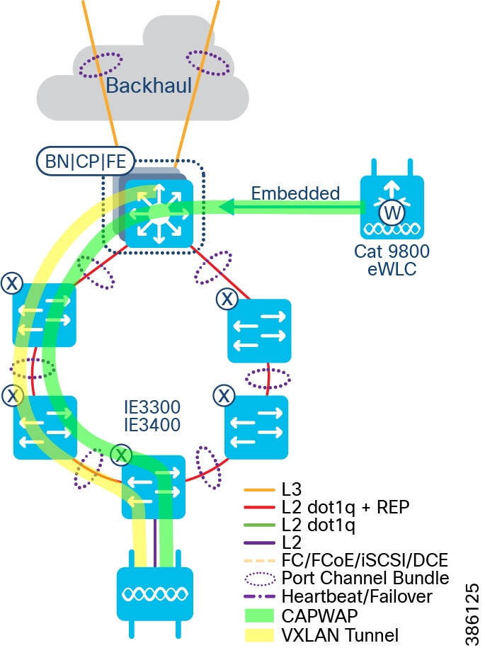
SDA Wireless APs connect to either Fabric Edge (FE) ports, or Extended Node (EN) ports. Client roaming is anchored via the Fabric Edge regardless of whether the APs are directly connected to FE or EN ports (this is even true of Policy Extended Nodes (PENs)).
Wi-Fi network management using DNA Center
Although the WLC has CLI and Web GUI for wireless management, when doing SDA Wireless, DNA Center is the primary management point. Onboarding of APs, defining wireless networks (and associated attributes) and applying these to different physical locations, is all done via the DNAC user interface. Corresponding visibility, troubleshooting and general reporting is done via the Assurance component within DNAC. It is not recommended to make changes via the WLC CLI or Web UI, as these may be overwritten by DNAC.
Comparison of Wi-Fi Deployment types
The table below provides a comparison of Wi-Fi deployment types, depending on the use cases CCI is being used to achieve.
Table 10 Wi-Fi deployment comparison
|
|
|
|
|
|
|
|
|
|
|
|
|
||
|
|
|
|
|
|
|
|
|
|
|
|
|
|
|
|
|
|
|
|
|
|
|
||
|
|
|
||
Repeating the guidance above, it is not possible to mix both types at a single PoP, however it is possible to have shared SSIDs between say SDA Wireless in PoP1 and CUWN Mesh in PoP2, although it should be noted that there will not be seamless roaming between them, and this scenario is best suited when the neighboring PoPs are sufficiently apart that any Wi-Fi client will not “see” the SSID from both simultaneously.
Cisco DNA Spaces
Cisco DNA Spaces is a location services platform, delivered as a cloud-based service. WLCs integrate with DNA Spaces, and as such must have an outbound path to the Public Internet. See https://dnaspaces.cisco.com/faqs/#deployment for other deployment options and integration points, however these are not covered in this CVD.
DNA Spaces has two licensing levels (see https://dnaspaces.cisco.com/packages/ for full details): “See” and “Act”. Which level that is the best fit for your CCI deployment depends on the use cases, but in general “See” gives Wi-Fi client computed location, tracking and analytics, with visualization and the ability to export all this data; “Act” adds captive portal, hyper-location, advanced analytics and API/SDK integration possibilities.
In general DNA Spaces is an optional component with the CVD, however for the Public Wi-Fi use case it is a mandatory component, as it is used for the guest (captive) portal, and as such “Act” licensing is required. DNA Spaces works with both CUWN with Mesh, and SDA Wireless Wi-Fi deployment types, with both leveraging the Catalyst 9800 WLC integration (both embedded and appliance) with DNA Spaces cloud service.
CCI Wireless IoT Devices Networks
This chapter, which discusses design of the CCI Wireless IoT Devices Networks, includes the following major topics:
CR-Mesh Network
A CR-Mesh network is a multi-service sub-gigahertz radio frequency solution. Cisco CR-Mesh networks are capable of supporting a large number of devices including but not limited to advanced metering, distributed automation, supervisory control and data acquisition (SCADA) networks, smart street lighting as well as a host of other use cases. In this section we cover the primary components and operation of a CR-Mesh network.
CR-Mesh is currently available for the 902-928Mhz band (and its subsets) only, therefore the countries where the band cannot be used are outside the scope of CG-Mesh usage.
CR-Mesh is Cisco deployment of IEEE 802.15.4g PHY and 802.15.4e MAC wireless mesh technology. Cisco CR-Mesh products are Wi-SUN Alliance certified starting with mesh version 6.1. The Wi-SUN Alliance is a global ecosystem of organizations creating interoperable wireless solutions. Though-out this document we will refer reference CR-Mesh and where applicable call out difference between CR-Mesh and Wi-SUN deployment strategies or implementation differences.
CR-Mesh is an IPv6 over Low power Wireless Personal Area Network (6LoWPAN). The 6LoWPAN adaptation layer adapts IPv6 to operate efficiently over low-power and lossy links such as IEEE 802.15.4g/e/v RF mesh. The adaptation layer sits between the IPv6 and IEEE 802.15.4 layers and provides IPv6 header compression, IPv6 datagram fragmentation, and optimized IPv6 Neighbor Discovery, thus enabling efficient IPv6 communication over the low-power and lossy links such as the ones defined by IEEE 802.15.4.
Routing Protocol for Low-Power and Lossy Networks (RPL) is a routing protocol for wireless networks with low power consumption and generally susceptible to packet loss. It is a proactive protocol based on distance vectors and operates on IEEE 802.15.4, optimized for multi-hop but supporting both star and mesh topologies.
CR-Mesh performs routing at the network layer using the Routing Protocol for Low-Power and Lossy Networks (RPL).
CR-Mesh implements the CSMP for remote configuration, monitoring, and event generation over the IPv6 network. The CSMP service is exposed over both the mesh and serial interfaces.
CR-Mesh Access Network Architecture
CR-Mesh in the CCI network
The CR-Mesh network components in CCI include Network Operation Center (NOC) and Data Centers (DC).
Network Operation Center (NOC) and Data Centers (DC)
The NOC is typically in close proximity to the data center which hosts the various applications that are relevant to CR-Mesh components of the network. Together systems in the NOC and data center provide operational visibility for the system managers to view and control the status of the network. Application management platforms, network communications management systems, and security systems are key to the operation of the network and are located in the data center and are displayed in the operations center.
Demilitarized Zone (DMZ)
The DMZ is a security buffer where security policy is created allowing data to traverse from one security zone to another.
Wide Area Network (WAN)
The WAN is responsible for providing the communications overlay between the extended network to the core. It can contain communications technology that is either private or public network, which is either owned by the operator or outsourced to a service provider. Popular WAN backhaul options are Ethernet and Cellular.
Neighborhood Area Network (NAN)
The NAN is the last mile network infrastructure connecting CR-Mesh endpoints to the access network. Endpoints communicate in the NAN across an IEEE 802.15.4g/e/v RF wireless network and connect to an access layer router.
Personal Area Network (PAN)
A unique PAN identifier (ID) is configured in the wireless interface of the access router where the CR-Mesh RF network connects to the CCI network. The PAN ID is a 16-bit field, described in the IEEE 802.15.4 specification. It is received and used by all devices grouped in the same PAN.
Each PAN in a NANA refers to a specific IEEE 802.15.4 radio in an access router.
Public cloud Services
Services that are available over the Internet and are not on the CCI network. (i.e. Cimcon LightingGale)
CR-Mesh Access Network Architecture depicts the solution architecture that covers various layers or places in the CR-Mesh network, system components at each layer, and the end-to-end communication architecture.
Figure 44 CR-Mesh Access Network Architecture
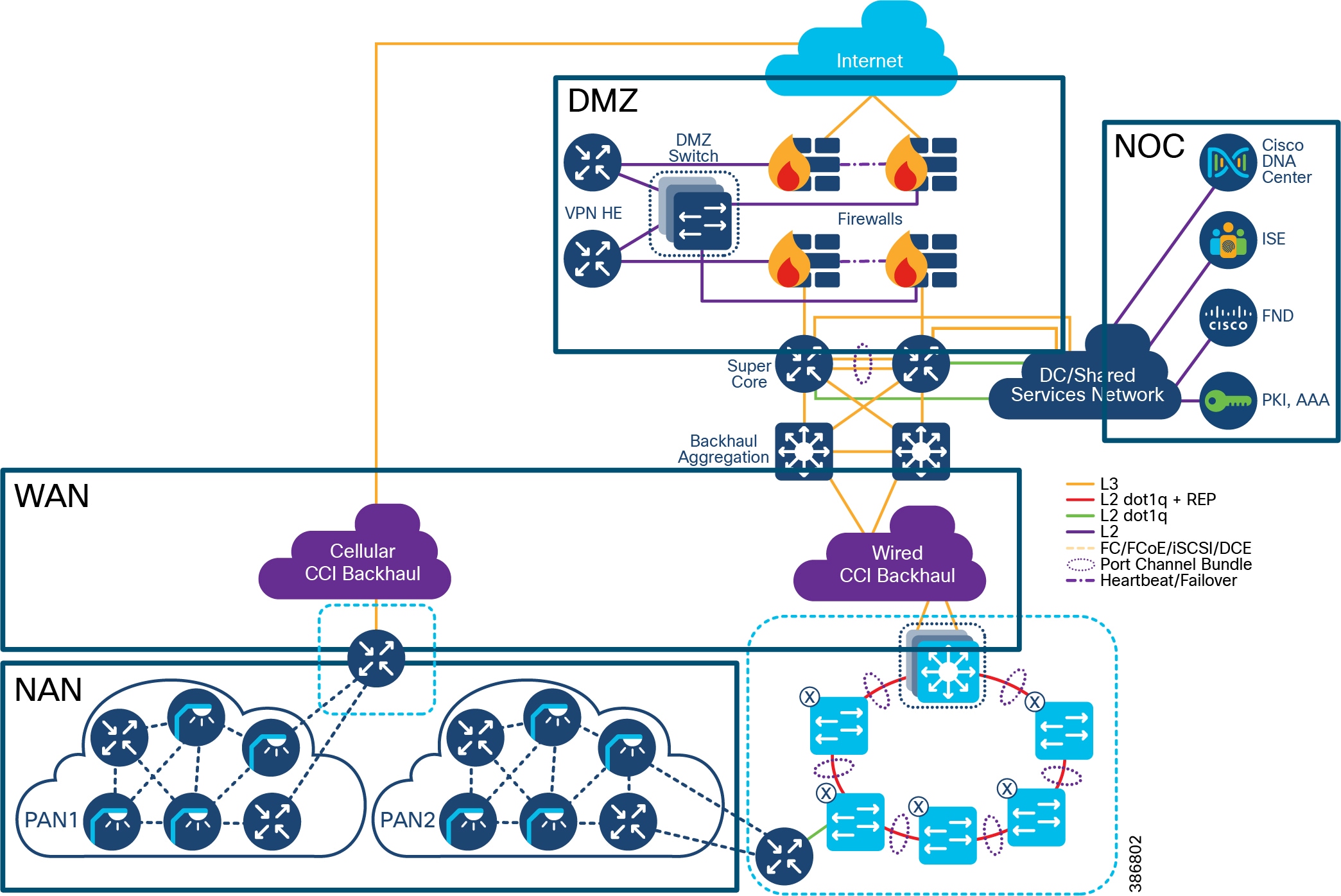
CR-Mesh Networking Components
Networking components reside in different areas of the network and perform a function such as making communications decision, authenticating devices and services, or enforcing security policy.
Headend Router (HER)
In the CR-Mesh access solution, the HER terminates the FlexVPN IPSec and GRE tunnels from the access layer routers. It may also establish FlexVPN IPSEC tunnels to public services outside of the CCI network. The HER cluster must be able to grow to support the number of access layer routers and tunnels that the network will require and should have redundancy.
In the CCI solution, the HER can be a virtual router or a dedicated router depending on the needs of the network. Cisco Cloud Services Router 1000V (CSR1000V) or Aggregation Service Router Series (ASR) routers are used as HERs.
Field Area Router (FAR)
The FAR acts as a network gateway for CR-Mesh endpoints by forwarding data from the endpoint to the headend systems. It is a critical element of the architecture since it ties the NAN and the WAN tier together.
The Cisco Connected Grid Router (CGR) along with 802.15.4g/e/v WPAN module are the Field Area Routers.
Connected Grid Endpoints (CGE)
CGEs are IP-enabled grid devices with an embedded IPv6-based communication stack. The CGEs form an IEEE 802.15.4e/g/v RF-based mesh network.
A CR-Mesh network contains endpoints known as CGEs within a Neighborhood Area Network (NAN) that supports end-to-end IPv6 mesh communication. CR-Mesh supports an IEEE 802.15.4e/g/v wireless interface and standards-based IPv6 communication stack, including security and network management. The CR-Mesh network provides a communication platform for highly secured two-way wireless communication with the CGE.
There are several types of CGE devices available:
- Cisco IR509 and IR510 gateway
- Third party CGE endpoints (i.e. Cimcon Street Light Controller)
- Cisco IR529 and IR530 range extender
Cisco provides a CGE radio module for incorporation into third party mesh endpoints. Cisco has a Solution Development Kit (SDK) that allow manufacture to rapidly develop their own endpoint. As a benefit to using the Cisco SDK developers can also streamline their testing towards Wi-SUN certification. Refer to the Cisco developer network to find out more information regarding this program.
The current implementation supports frequencies in the range of 902-928 MHz, with 64 non-overlapping channels and 400 kHz spacing for North America. A subset of North America frequency bands are for Brazil.
Figure 45 Connected Grid Endpoint Standards-based Communications Stack
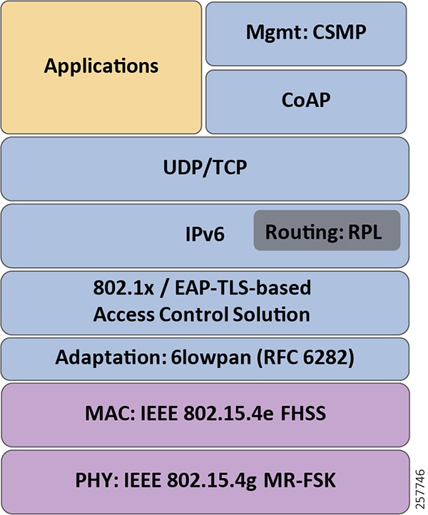
Phy Mode 98 with FEC enabled is the recommended CGE configuration.
CR-Mesh WPAN interface in CGR Router
In the CCI architecture, Cisco 1000 Series Connected Grid Routers are used as FARs. The Cisco Connected Grid Router (CGR) 1240 is specifically designed for outdoor deployments while Cisco Connected Grid Router (CGR) 1120 is suited for indoor deployments. However, Cisco Connected Grid Router (CGR) 1120 with suitable enclosures can also be installed in outdoors in a field installation, with antennas mounted outside the enclosure.
The Cisco Connected Grid Router (CGR) is a modular platform providing flexibility to support several choices of interfaces to connect to a WAN backhaul, such as Ethernet and Cellular.
The Cisco Connected Grid Router (CGR) 1240 can be provisioned with up to two WPAN modules that provide IPv6-based, IEEE 802.15.4g/e/v compliant wireless connectivity to enable CCI applications. The two modules can act as independent WPAN networks with different SSIDs or can be in a primary-subordinate mode increasing the density of PHY connections. The module is ideal for standards based IPv6 multi-hop mesh networks and long reach solutions. It helps enable a high ratio of endpoints to the CGR.
Cisco has certified the WPAN physical interface (PHY) for Wi-SUN 1.0 compliance.
CR-Mesh Range Extension
Cisco range extenders provide unlicensed 902-928Mhz, ISM-band IEEE 802.15.4g/e/v wireless personal-area network (WPAN) communications. It extends the range of the RF wireless mesh network, providing longer reach between WPAN endpoints (CGEs) and the WPAN Field Area Routers (FARs). The Cisco IR530 range extender is a high performance, new generation of the Cisco RF Mesh range extender.
- World class IPv6 Networking
- Highly Secure and Scalable
- IEEE 802.15.4, g/e/v, IETF 6LoWPAN
- Wi-SUN 1.0 PHY Certified
- IETF Routing Protocol for Low Power and Lossy Networks (RPL)
- IETF Constrained Application Protocol (CoAP)
- Product Guides - https://www.cisco.com/c/en/us/support/routers/510-wpan-industrial-router/model.html
CR-Mesh WPAN Industrial Router
Cisco industrial routers / gateways provide unlicensed 902-928Mhz, ISM-band IEEE 802.15.4g/e/v wireless personal-area network (WPAN) communications. These routers supply enterprise-class RF mesh connectivity to IPv4, IPv6 and RS-232 serial devices. Cisco IR510 provides higher throughput to support IoT use cases in distributed intelligence and supervisory control and data acquisition (SCADA).
- World class IPv6 Networking
- Highly Secure and Scalable
- IEEE 802.15.4, g/e/v, IETF 6LoWPAN
- IETF Routing Protocol for Low Power and Lossy Networks (RPL)
- IETF Constrained Application Protocol (CoAP)
- IETF Mapping of Address and Port – Translation (MAP-T)
- Wi-SUN 1.0 PHY Certified
- DC Power input 9.6-60VDC, 7 watts of power consumption
- 10/100 Fast Ethernet port
- RS-232/RS-485 serial port
- Digital alarm input
- Raw socket support on serial ports
- SCADA Support
- Dying gasp
- Network and Transport Layer: IPv4, IPv6, RPL, NAT44, MAP-T, Leaf node, Static NAT
- Product guides - https://www.cisco.com/c/en/us/support/routers/510-wpan-industrial-router/model.html
Data Center Services
Network Time Protocol (NTP) Server
NTP delivers time accuracies of 10 to 100 milliseconds over the CCI network, depending on the characteristics of the synchronization source and network paths in the WAN.
AAA and Directory Services
RADIUS provides authorization and authentication services for CR-Mesh.
RSA Certification Authority
During the pre-staging process, RSA CA-signed RSA certificates are provisioned in FAR. The RSA CA-signed certificates are also provisioned in HER. In order to verify RSA CA signed certificates, the RSA CA public key is loaded at FAR and HER. Thus, HER and FAR can verify authenticity of each other's certificate.
ECC Certification Authority
ECC CA security keys are authenticated by AAA during CGE onboarding.
Figure 46 Components in the CR-Mesh network
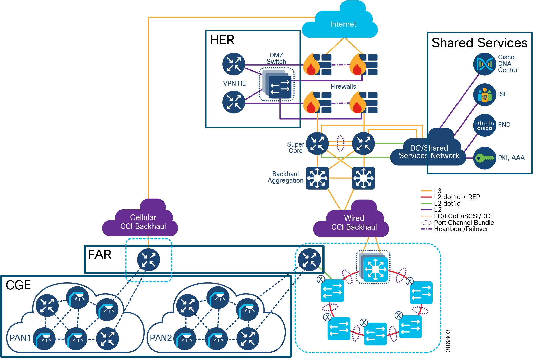
Cisco CR-Mesh network solution operations comprise of six major topics:
Frequency Hopping Spread Spectrum Types
CR-Mesh implements Frequency Hopping Spread Spectrum (FHSS) using two methods in the 902 to 928 MHz ISM band:
- Two Frequency Shift Keying (2FSK): 64 channels, 400-kHz spacing
- Orthogonal frequency Division Multiplexing (OFDM): 31 channels, 800kHz channel spacing
The frequency-hopping protocol used by CR-Mesh maximizes the use of the available spectrum by allowing multiple sender-receiver pairs to communicate simultaneously on different channels. The frequency hopping protocol also mitigates the negative effects of narrowband interferers.
CR-Mesh allow each communication module to follow its own channel-hopping schedule for unicast communication and synchronize with neighboring nodes to periodically listen to the same channel for broadcast communication. This enables all nodes within a CGE PAN to use different parts of the spectrum simultaneously for unicast communication when nodes are not listening for a broadcast message.
Wi-SUN 1.0 and CR-Mesh support 2FSK narrowband modulation schemes. While 2FSK is effective for applications like smart metering, they can encounter group delay and narrowband interference in complex or highly contested environments. In addition to 2FSK, CR-Mesh supports OFDM radio management technology. OFDM employs frequency-division multiplexing and advanced channel coding techniques enabling reliable transmission and improved data rates in more complex and contested environments. Future releases of Wi-SUN will support OFDM, Cisco will also release a future OFDM reference design. Current Cisco OFDM CR-Mesh devices (IR510 and OFDM WPAN module) are backwards compatible supporting both OFDM and 2FSK devices, but not CR-Mesh and Wi-SUN 1.0 simultaneously. Wi-SUN 1.0 has a different MAC frame format and flow control preventing interoperability between Wi-SUN and CR-Mesh
This guide and the supporting implementation guide will explore combining both FSK and OFDM devices on a neighborhood area network (NAN).
Frequency Shift Keying (FSK)
FSK is a digital modulation technique in which the frequency of the carrier signal varies according to the digital signal changes. The output of an FSK modulation high frequency wave represents a high (binary 1) input value and a low frequency wave represents a low (binary 0).
The following image is the representation of the FSK modulated waveform along with its binary representation.
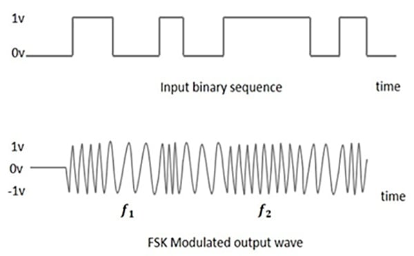
Orthogonal Frequency Division Multiplexing (OFDM)
OFDM is a digital modulation technique where data is transmitted over different subcarriers. OFDM modulation contains overlapping spectra, but the signals are orthogonal and have in interaction with each other.
The following image represents data being transmitted over various sub-carriers.

FSK and OFDM comparisons
While networks may have to operate with both FSK and OFDM for some time, network operators may be able to bypass FSK networks to OFDM networks based on endpoint selection. They may also want to ensure that the key network equipment supports both FSK and OFDM. The obvious advantages of OFDM limit the feasibility of installing only an FSK network. Interoperability between FSK and OFDM are discussed later in this document.
- FSK uses a single carrier while OFDM makes efficient use of the spectrum by allowing carrier overlap
- OFDM divides the channel into narrowband flat fading subchannels, making it more resistant to frequency selective fading that exist in single channel systems (FSK)
- OFDM has adequate channel coding and interleaving to recover data (symbols) lost due to frequency selectivity of the channel
- FSK is more sensitive to sample timing offsets than OFDM
- OFDM allows more decoding techniques and complexity in deployment options
- OFDM provides better protection against co-channel interference and impulsive parasitic noise
- OFDM supports higher data rates and wider channel spacing
- OFDM has better channel resiliency
Table 11 Frequency Hopping Spread Spectrum (FHSS) RF Modulation and PHY Data Rates
Table 12 Hardware and Software Specifications of Cisco Connected Grid Router (CGR) WPAN Modules
Radio Frequency Area Setup
A CR-Mesh network is a secure end to end network meaning, the CGE devices contain certificates that identify them as part of the network they are joining. The endpoints are either configured at that factory or restaged onsite with the networks Service Set Identifier (SSID) and security certificates that are required and generated from the host network. Without the proper SSID the device will not find the proper host network and without certificates from the host network the endpoint will be refused an IP address when they request to join the network over the configure SSID.
The CR-Mesh SSID is advertised through IEEE 802.15.4e enhanced beacons which can also pass additional vendor information. Enhanced Beacon (EB) messages allow communication modules to discover PANs that they can join. The EB message is the only message sent in the clear that can provide useful information to joining nodes. CGRs drive the dissemination process for all PAN-wide information.
Joining devices also use the RSSI value of the received EB message to determine if a neighbor is likely to provide a good link. The transceiver hardware provides the RSSI value. Neighbors that have an RSSI value below the minimum threshold during the course of receiving EB messages are not considered for PAN access requests.
RFC 768 User Datagram Protocol (UDP) is the recommended transport layer over 6LoWPAN. Table 21 summarizes the protocols applied at each layer of the NAN.
Table 13 Summary of Network Protocols in the NAN
|
|
|
|
|
|
|
|
|
|
|
|
|
|
The CR-Mesh network defines a SSID, which identifies the owner of the resilient mesh. The SSID is programmed on the CGE, and that same SSID must also be configured on the Cisco Connected Grid Router (CGR) WPAN interface during deployment.
A CR-Mesh NAN is subdivided into one or more Personal Area Networks (PAN). Each PAN has a unique PAN-ID. A PAN-ID is assigned to a single WPAN module installed within an FAR. All CGEs within a PAN form a single CR-Mesh network.
Figure 49 PAN, NAN and SSID locations in the network
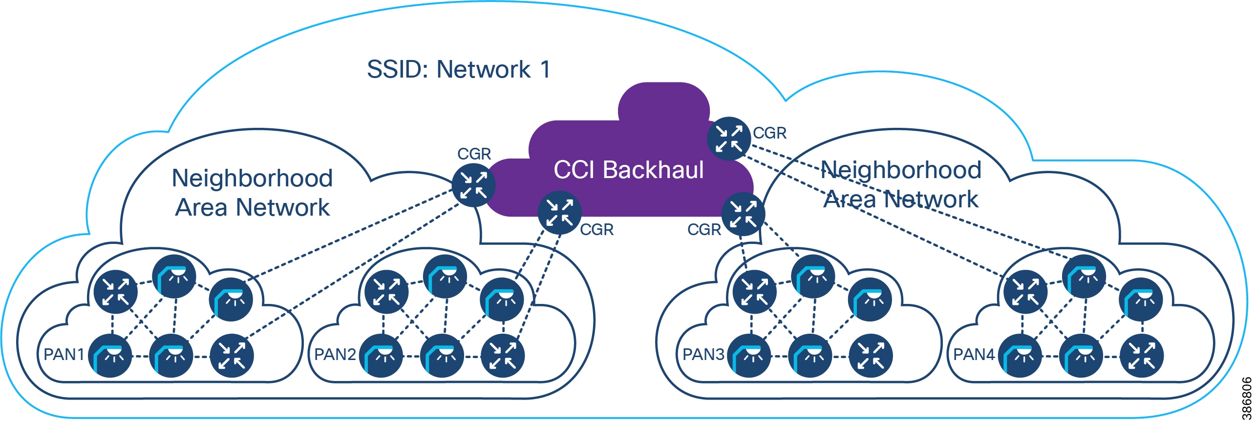
CR-Mesh Authentication and Data Flow
There are several requirements for the CCI infrastructure to support a CR-Mesh installation. Layer 3 interfaces on the FAR, such as Ethernet/fiber or cellular, must be enabled and properly addressed. Route entries must be added on the head-end router. The FAR is connected to the HER using secure IPSEC FlexVPN tunnels. Loopback interfaces must be enabled for network management, local applications, and tunnel or routing configuration must be completed.
- Stage the FAR with bootstrap configuration to call home to the headend network
- FAR is powered up and acquires Certificates from PKI infrastructure in Headend for HTTPs communication
- FAR initiates communication with the tunnel provisioning proxy which forwards request to FND behind firewall
- FND configures Flex/IPsec tunnels on the FAR and ASR
- FAR now registers with the FND through the Tunnel
- CR mesh related configuration should be prestaged in the FND and pushed via the FND once the FAR registers
CGE onboarding to the CR-Mesh network:
- CGE are field configured with EUI64 (MAC), SSID, regional compliance factors, CGE identity CA certificate, or NMS certificate.
- Once the FAR registers the FND pushes down WPAN configuration to start onboarding crmesh devices
- CR mesh authenticate with AAA servers in headend and acquire x.509 certificates and Join the FAR WPAN link neighbor table and start process of acquiring DHCPv6 address
- Once DHCP address is acquired the CRMesh RPL protocol allows the mesh to join the PAN and send a registration request to the FND
- CGE become manageable via CoAP Simple Management Protocol (CSMP) once they are registered with FND
Proper time synchronization is required to support the use of certificates on network equipment and CGE devices. The network management services (FND) is configured and ready to accept clients. Certificates are generated from a public key infrastructure on the CCI network and the network can support IPv6 traffic natively or through the use of GRE tunnels.
If the network has been prepared to accommodate all of the above requirements, the endpoints are staged with the network SSID and unique PKI certificate for each device.
As endpoints are powered on, each device attempts to connect to their programmed SSID. The FAR hosting the SSID should hear the request if the endpoint is within range. A proper site survey should have been completed prior to deploying the CGE in their final locations to guarantee communication and RF coverage with redundancy/fail-over planning.
The FAR will than begin to authenticate the endpoint. First the FAR will validated the endpoints certification key using RADIUS services. After the device is validated, the device will be assigned an IP address from the data center DHCP server.
After successful authentication and IP assignment the endpoint will be able to communicate across the CCI network if proper DMZ traffic policies are enabled. The endpoint should be able to communicate with the management systems (FND) for operational status and device management including firmware updates, mesh formation, and device status.
In some cases, the device will also need access to public cloud services. Additional security policies may need to be created to ensure the communication to these services are available. Also, since these endpoints are communicating as IPv6 endpoints additional consideration may be needed to encapsulate traffic from these devices across the network to the public cloud-based services. The public cloud services may be running native IPv6 to communicate to the endpoint essentially requiring an end-to-end IPv6 communications path from the endpoint to the public cloud services.
CR-Mesh Access Network Architecture with a Smart Street Lighting Solution depicts the CR-Mesh access network solution across the CCI network, system components at each layer, and the end-to-end communication path.
Figure 50 CR-Mesh Access Network Architecture with a Smart Street Lighting Solution
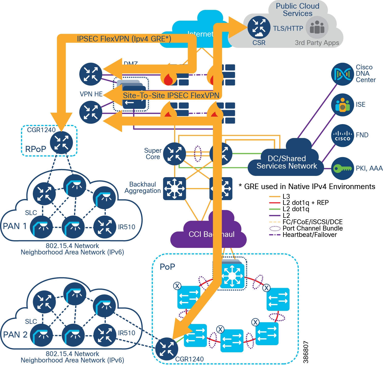
After endpoints are onboarded to the network and the network is in an operational state, CR-Mesh performs routing at the network layer using the Routing Protocol for Low-Power and Lossy Networks (RPL). The CGEs act as RPL Directed Acrylic Graph (DAG) node, whereas the FAR serves as the RPL DAG root. The FAR runs RPL protocol to build mesh network and serves as the RPL root.
When a routable IPv6 address is assigned to its CG-Mesh interface, the CGE sends Destination Advertisement Object (DAO) messages informing the DAG root (FAR) of its IPv6 address and the IPv6 addresses of its parents. Using the information in the DAO messages, the FAR builds the downstream RPL route to CGE. A Destination Oriented Directed Acrylic Graph (DODAG) is formed, which is rooted at a single point, namely the FAR. The FAR constructs a routing tree of the CGEs. When an external device such as FND try to reach the CGE, the FAR routes the packets with source routing.
The RPL tree rooted at the FAR can be viewed at the FAR. In the RPL tree, a CGE can be a part of a single PAN at a time. Cisco FND monitors and manages the CGEs with CSMP protocol.
Interoperability of FSK and OFDM endpoints and devices
CR-Mesh endpoints can support various phy modes under the adaptive modulation feature which allows both FSK and OFDM modulation schemes to coexist. The Link can operate in both modes, eg the forwarder can use phy mode 66 (2FSK 150KBps) and reverse path can use phy mode 166 (OFDM 800KBps). The entire PAN can use various modes based on channel conditions.
When Resilient Mesh nodes supports several IEEE 802.15.4g PHY modes, adaptive modulation enables Resilient Mesh nodes changing their data rate on a packet-by-packet basis to increase the reliability of the link.
Two methods are used to enable a Resilient Mesh node to switch data rate:
- OFDM modulation switch - RF driver can decode frames with different data rates according to PHY header MCS values
- MR-FSK modulation switch – based on MR-FSK mode switch header. When MR-FSK mode switch header is received, Resilient Mesh Endpoints, supporting mode switching, change their PHY mode to the new PHY mode defined in the MR-FSK mode switch header, in order to receive the following packets
To ensure compatibility the WPAN module should support both FSK and OFDM. Cisco OFDM WPAN modules are backwards compatible to FSK. Using an OFDM WPAN module allows endpoints to be either FSK or OFDM. Mixing endpoint types allows for easy migration between technologies.
Scale and Redundancy
In the figure below if the FAR that is hosting PAN1 where to fail and the devices on PAN1 would be orphaned. If a CGE was in range of either the PAN2 WPAN interface in the second FAR the devices and theoretically all the other devices would fail over to PAN2.
Optionally, a second WPAN could be configured as a standby to PAN1 in close proximity to the existing FAN router.
Failover is dependent on the ability for the CGEs to hear other CGE or WPAN interfaces in the same SSID.
Figure 51 CR-Mesh Access Network Architecture with a Smart Street Lighting Solution in RPoP
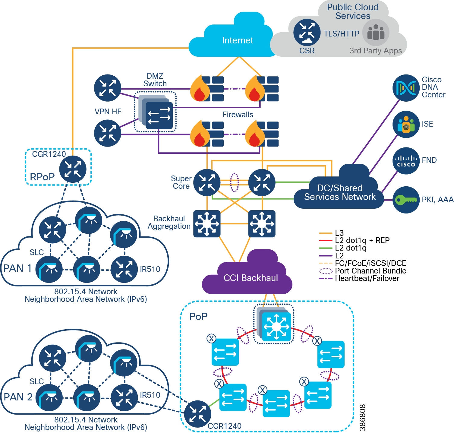
Ongoing Operation
CGE Firmware Upgrade Procedure
The CR-Mesh CGE firmware can be installed by CLI or from Cisco FND using the CSMP protocol and multicast over IPv6.
For more information on upgrading the firmware, see the latest Release Notes for the Cisco 1000 Series Connected Grid Routers for Cisco IOS Release at the following URL:
Compromised CGE or Network Device Eviction
A compromised endpoint is one where the CGE can no longer be trusted by the network and/or operators. Nodes within an IEEE 802.15.4 PAN must possess the currently valid Group Temporal Key (GTK) to send and receive link-layer messages. The GTK is shared among all devices within the PAN and is refreshed periodically or on-demand. By communicating new GTKs to only trusted devices, compromised nodes may be evicted from the network and the corresponding entry is removed from the AAA/NPS server, preventing the device from rejoining the network without a new valid certificate. Additional devices that could be evicted from the network include any infrastructure components that have been joined using a PKI certificate.
Power Outage Notification
CR-Mesh supports timely and efficient reporting of power outages and restorations. In the event of a power outage, CR-Mesh endpoints enter power-outage notification mode and the CGE stops listening for traffic to conserve energy. The CGE network stack and included SDK triggers functions to conserve energy by notifying the communication module and neighboring nodes of the outage. The outage notification is sent using Cisco Connected Grid Router (CGR) battery backup with the same security settings as any other UDP/IPv6 datagram transmission to Cisco FND. This is documented as the “last gasp” feature of the CGR FAR.
In the event of a power restoration, a CR-Mesh endpoint sends a restoration notification using the same communication method as the outage notification. The communication modules unaffected by the power outage event deliver the restoration notification.
CR-Mesh Access Network Solution IP Addressing
For most CR-Mesh deployments, address planning will be required. The IPv4 addressing plan must be derived from the existing enterprise scheme while the IPv6 addressing plan will most likely be new. In all cases, the network needs to be dual-stack (IPv4, IPv6) capable.
CR-Mesh IPv4 and IPv6 Capable Device shows CR-Mesh devices with their IPv4 and IPv6 capabilities.
Table 14 CR-Mesh IPv4 and IPv6 Capable Device
The following communication flows occur over IPv6:
All other communications can occur over IPv4.
IPv4 address to all devices in the network are statically configured, IPv6 address to CGE are allocated by CPNR. CGE also receives FND IPv6 address and application server IPv6 address during DHCP allocation. As CCI currently does not support IPv6 endpoints, at the access network, this traffic is encapsulated in FlexVPN over IPv4.
LoRaWAN Access Network
This section discusses design of the CCI LoRaWAN Access Network for endpoint connectivity.
LoRaWAN Access Network
LoRa (Long Range) is a radio modulation technology for wireless communication. It is proprietary and owned by Semtech, which drives the technology via the LoRa Alliance where the open LoRaWAN protocol and ecosystem is developed.
The LoRa technology achieves its long-range connectivity (up to 10km+) by operating in a lower radio frequency that trades off data rate. Because its data rates are below 50kbps and because LoRa is limited by duty cycles and other restrictions, it is suitable in practice for non-real time applications for which one can tolerate delays.
LoRaWAN operates in an unlicensed (ISM band) radio spectrum. Each country/region allocates radio spectrum for LoRaWAN usage with regional parameters to plan out the regional frequency plan and channel usage.
In Europe, LoRaWAN operates in the 863-870 MHz frequency band, while in the US, LoRaWAN operates in the 902-928 MHz frequency band. The diagram below shows spectrum allocations for different countries/regions.
LoRaWAN is a Media Access Control (MAC) layer protocol running on top of the LoRa radio as the physical layer. It is designed to allow low-power devices to communicate with applications over long-range wireless connections.
Some of the key benefits of the LoRaWAN access technology include:
- Long range (up to 15km)
- Low cost radio, enabling low cost devices
- Low power given the opportunity for small battery powered sensors with 5-10 years+ battery life
- End-to-end encryption and Over the Air Activation (OTAA) for devices
- Strong industry forum via the LoRa Alliance ® with more than 500 members (including Cisco); for more information, please refer to:
Figure 52 LoRaWAN Protocol Layers (source: LoRaWAN™ Specification)
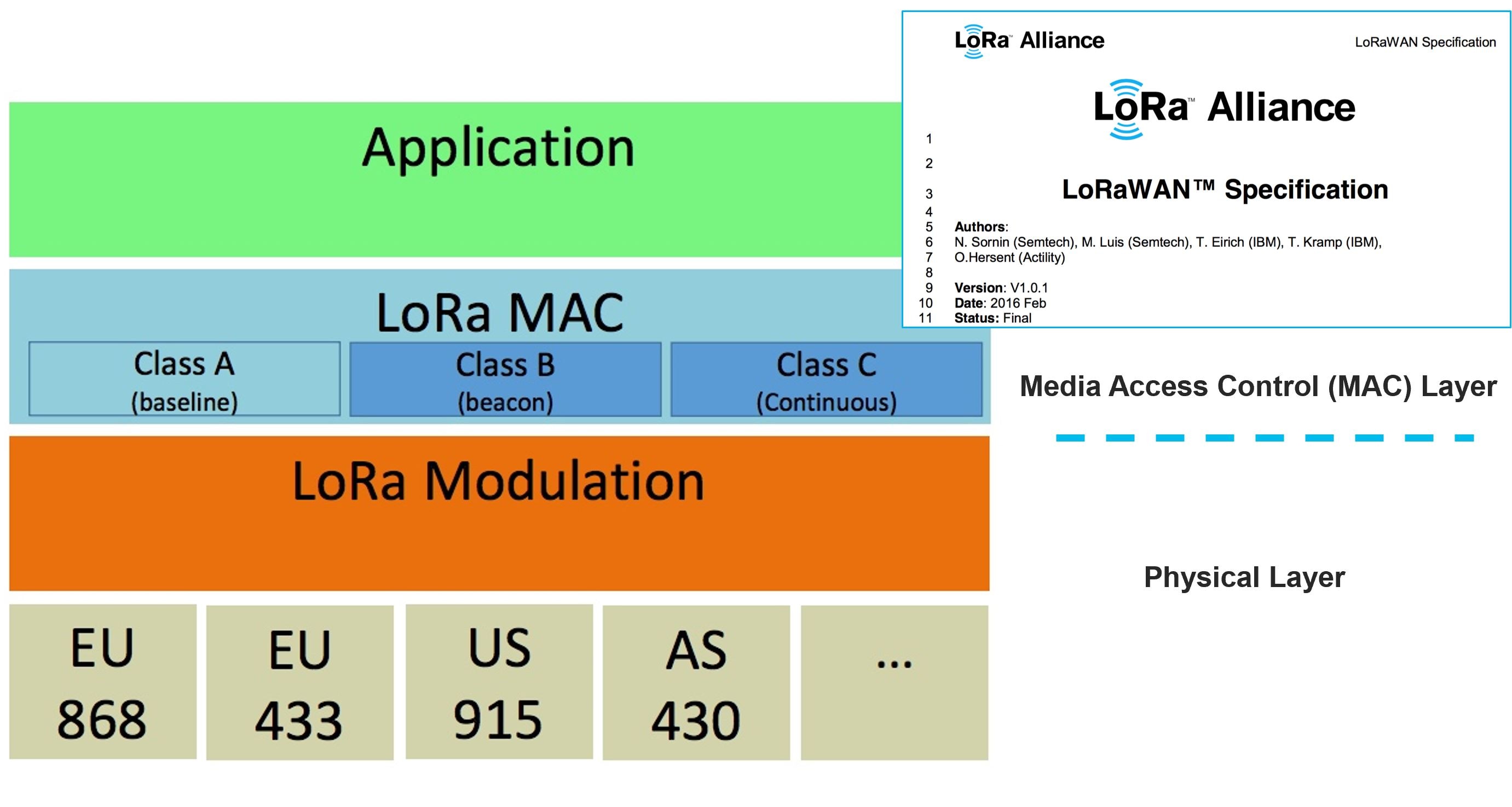
An End-to-End LoRaWAN architecture is illustrated in LoRaWAN End-to-End Architecture.
Figure 53 LoRaWAN End-to-End Architecture
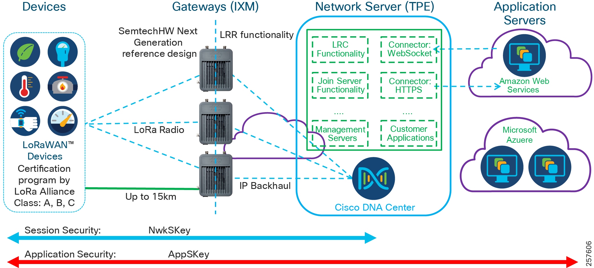
CCI can support a broad set of use cases using LoRaWAN technology. Key Smart City use cases include:
–![]() Parking occupancy and availability
Parking occupancy and availability
–![]() Utilization reports and analytics
Utilization reports and analytics
–![]() Waste Bin sensor battery level
Waste Bin sensor battery level
–![]() Software modeling of air quality
Software modeling of air quality
–![]() Water levels and flood sensing/detection
Water levels and flood sensing/detection
Note: For more use case details refer to the use case section of this document.
The architecture components include LoRaWAN devices, LoRaWAN Gateways, Network Server, and Application Servers. The LoRaWAN devices to Network Server and Application Servers are secured by keys, which are exchanged between devices and servers during device over-the-air on-boarding process. In a CCI deployment, LoRaWAN gateways are managed with Cisco FND, the Cisco network management system for gateways. More detail of each solution components is described below.
LoRaWAN Devices
- LoRaWAN devices categorized into three classes: Class A, B, and C. All LoRaWAN devices must implement Class A, whereas Class B and Class C are extensions to the specific Class A devices.
–![]() Class A devices—Support bi-directional communication between a device and a gateway. Uplink messages can be sent at any time from the device, typically as a triggered event or a scheduled interval. Then the device can receive messages at two receive windows at specified times after the uplink transmission. If no message is received, the device can only receive messages after the next uplink transmission.
Class A devices—Support bi-directional communication between a device and a gateway. Uplink messages can be sent at any time from the device, typically as a triggered event or a scheduled interval. Then the device can receive messages at two receive windows at specified times after the uplink transmission. If no message is received, the device can only receive messages after the next uplink transmission.
–![]() Class B devices—Support scheduled receive windows for downlink messages. Devices can receive messages in the scheduled receive windows; this is not limited to receiving messages only after being sent.
Class B devices—Support scheduled receive windows for downlink messages. Devices can receive messages in the scheduled receive windows; this is not limited to receiving messages only after being sent.
–![]() Class C devices—Support receive windows open unless they are transmitting to allow low-latency communication. However, Class C devices consume much more energy compared to Class A devices.
Class C devices—Support receive windows open unless they are transmitting to allow low-latency communication. However, Class C devices consume much more energy compared to Class A devices.
- LoRaWAN devices are certified by LoRa Alliance to ensure interoperability.
- LoRaWAN device activation can be completed in two ways:
–![]() OTAA: Over the air activation
OTAA: Over the air activation
–![]() ABP: Activation by personalization
ABP: Activation by personalization
Earlier release of CCI added LoRaWAN devices via the ABP process. When using ABP, unique hardcoded DevAddr and security keys are manually entered at the time a device joins and remain the same until physically changed.
OTAA is more secure and the recommended method for onboarding LoRaWAN devices. Dynamic DevAddr are assigned and security keys are negotiated with the device as part of the join-procedure. OTAA also makes it possible for devices to join other networks.
LoRaWAN Gateways
- LoRaWAN Gateways receive messages from devices across the LoRaWAN network, encapsulate the message into IP, and forward the message to the Network Server over IP Backhaul.
- Conversely, LoRaWAN messages from the application or the network server will be sent through the best available gateway, determined by the network server, to reach the device.
- The Cisco Wireless Gateway for LoRaWAN is the solution component chosen in the CCI infrastructure. It has the following functionality:
–![]() Cisco Wireless Gateway for LoRaWAN can be a standalone gateway (Ethernet backhaul) or an IOS interface (Integrated Interface) on Cisco IR809, IR829 router. A LoRaWAN gateway can be part of a wired CCI network located in a PoP or connected over a cellular network from a RPoP.
Cisco Wireless Gateway for LoRaWAN can be a standalone gateway (Ethernet backhaul) or an IOS interface (Integrated Interface) on Cisco IR809, IR829 router. A LoRaWAN gateway can be part of a wired CCI network located in a PoP or connected over a cellular network from a RPoP.
–![]() Cisco Wireless Gateway for LoRaWAN adopts Semtech Next Gen gateway reference design (known as v2 gateway).
Cisco Wireless Gateway for LoRaWAN adopts Semtech Next Gen gateway reference design (known as v2 gateway).
The Linux container (LXC) in the Cisco Wireless Gateway for LoRaWAN runs Actility long range router (LRR) packet forwarder image, which interworks with Actility Network Server long range controller (LRC) functionality for radio management
–![]() Carrier and industrial grade: IP67 rating, PoE+ power, GPS, main and diversity antennas.
Carrier and industrial grade: IP67 rating, PoE+ power, GPS, main and diversity antennas.
–![]() Fully complies with LoRaWAN specifications 1.0x and 1.1.
Fully complies with LoRaWAN specifications 1.0x and 1.1.
–![]() Two hardware SKUs: IXM-LPWA-800-16-K9 (868 MHz) and IXM-LPWA-900-16-K9 (915 MHz).
Two hardware SKUs: IXM-LPWA-800-16-K9 (868 MHz) and IXM-LPWA-900-16-K9 (915 MHz).
–![]() Supports LoRaWAN regional RF parameters profiles through the LoRaWAN network server solution.
Supports LoRaWAN regional RF parameters profiles through the LoRaWAN network server solution.
–![]() Supports LoRaWAN devices class A, B, and C.
Supports LoRaWAN devices class A, B, and C.
–![]() Enables flexible topologies: standalone for Ethernet backhaul, one to multiple Cisco LoRaWAN Interface modules on Cisco IR809/IR829 routers.
Enables flexible topologies: standalone for Ethernet backhaul, one to multiple Cisco LoRaWAN Interface modules on Cisco IR809/IR829 routers.
Network Server
- LoRaWAN messages sent by a device are broadcast and can be received by multiple LoRaWAN gateways within the range. The Network Server de-duplicates multiple copies of the same message for further process.
- The messages received are LoRaWAN MAC layer messages. See LoRaWAN MAC Messages for message types.
- The Network Server performs the following functions based on the message type it received:
|
|
|
|---|---|
–![]() Over-the-air activation (OTAA)—Each LoRaWAN device is equipped with a 64-bit DevEUI, a 64-bit AppEUI, and a 128-bit AppKey. The DevEUI is a globally unique identifier for the device that has a 64-bit address comparable with the MAC address for a TCP/IP device. The AppKey is the root key of the device. All three values are then made available to the Network Server to which the device is supposed to connect. The device sends the Join Request message, composed of its AppEUI and DevEUI. It additionally sends a DevNonce, which is a unique, randomly generated, two-byte value used for preventing replay attacks.
Over-the-air activation (OTAA)—Each LoRaWAN device is equipped with a 64-bit DevEUI, a 64-bit AppEUI, and a 128-bit AppKey. The DevEUI is a globally unique identifier for the device that has a 64-bit address comparable with the MAC address for a TCP/IP device. The AppKey is the root key of the device. All three values are then made available to the Network Server to which the device is supposed to connect. The device sends the Join Request message, composed of its AppEUI and DevEUI. It additionally sends a DevNonce, which is a unique, randomly generated, two-byte value used for preventing replay attacks.
These three values are signed with a 4-byte Message Integrity Code (MIC) using the device AppKey. The server accepts Join Requests once it validates these keys and the MIC value and responds the Join Accept message.
The Join Accept message is encrypted by APPKey with information about NetID, DevAddr, and additional local parameters.
This completes the device activation process to allow device to communicate with the application server to send and receive information in encrypted format only can be decoded by the server with the appropriated keys.
Information Elements for MAC Messages lists the key information details:
Figure 54 Information Elements for MAC Messages
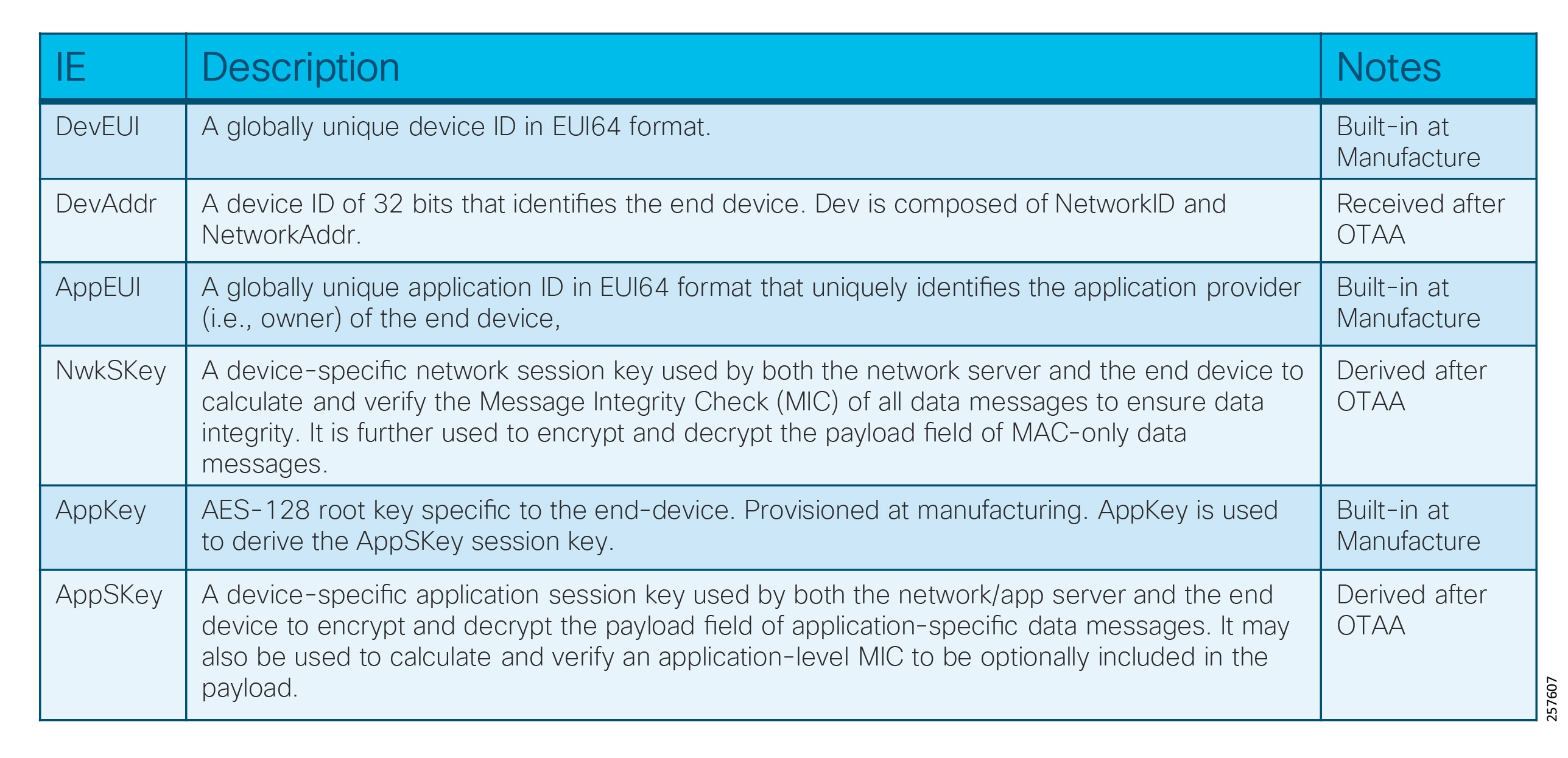
LoRaWAN Device OTAA Procedures depicts the call flow of OTAA procedures:
Figure 55 LoRaWAN Device OTAA Procedures
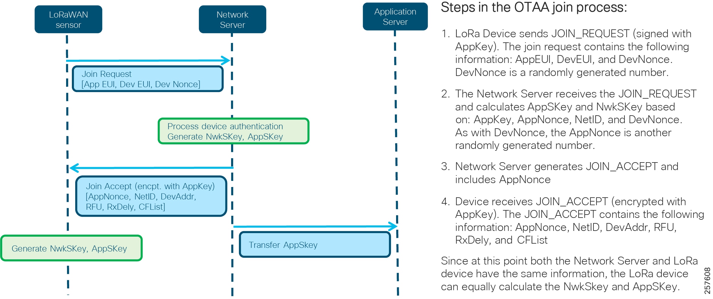
- Data messages: The messages can be uplink or downlink messages, with or without acknowledgment by the receivers. The Network Server uses NwkSKey to validate the message integrity and prepare the payload of the data messages (message type of 010, 011, 100, 101) to the corresponding application server by publishing the message to a data connector used by the applications.
- Network Server dynamically selects the best gateway for optimized sensor data traffic routing.
- Implements Adaptive Data Rate (ADR) scheme to optimize the individual data rates and RF output of each connected device to allow more end devices to communicate.
- Network Server supports reporting and administration functions.
- Actility Network Server ThingPark Enterprise (TPE) (available on the Cisco Global Price List) is the network server validated in the CCI infrastructure.
Application Server
- An application is a collection of devices with the same purpose, of the same type.
- An Application Server typically resides in the cloud or on-premise and collects information from devices of the same purpose and of the same type.
- The Application Server uses AppSKey to de-encrypt the message to ensure data security.
- An Application Server may offer web interface for users to manage/view devices as well as data collected from the devices.
- An Application Server may also offer an API such as RESTFUL for integration with external services.
- The CCI infrastructure supports Application Servers as long as it is able to connect with Actility Network Server using a supported connector such as HTTPS, WebSocket, etc. For a complete list of connectors supported by Actility, refer to the following URL:
–![]() https://dx-api.thingpark.com/dataflow/latest/product/connectors.html
https://dx-api.thingpark.com/dataflow/latest/product/connectors.html
Management of LoRaWAN solution components listed above are achieved in two steps. First, bring up Cisco Wireless Gateway for LoRaWAN manually and then use the Actility Management tool as described below:
1.![]() On Cisco Wireless Gateway for LoRaWAN gateway:
On Cisco Wireless Gateway for LoRaWAN gateway:
a.![]() Load the desired IOS image to Cisco Wireless Gateway for LoRaWAN manually.
Load the desired IOS image to Cisco Wireless Gateway for LoRaWAN manually.
b.![]() Load the LRR image to Cisco Wireless Gateway for LoRaWAN to IXM container manually.
Load the LRR image to Cisco Wireless Gateway for LoRaWAN to IXM container manually.
c.![]() Set up proper configuration of Cisco Wireless Gateway for LoRaWAN.
Set up proper configuration of Cisco Wireless Gateway for LoRaWAN.
Refer to the Cisco Wireless Gateway for LoRaWAN Software Configuration Guide for more details.
2.![]() On ThingPark Enterprise (TPE) server:
On ThingPark Enterprise (TPE) server:
a.![]() Add Cisco Wireless Gateway for LoRaWAN information into the Base Station list.
Add Cisco Wireless Gateway for LoRaWAN information into the Base Station list.
b.![]() Then add the sensor information and application information to the TPE management tool as described in Actility ThingPark Enterprise Management Portal.
Then add the sensor information and application information to the TPE management tool as described in Actility ThingPark Enterprise Management Portal.
Actility ThingPark Enterprise Management Portal
–![]() Device Manager—It manages device list creation to allow devices to join the network. Once a device is created, it provides device status information along with associated device parameters such as DevEUI, DevAddr, RSSI, SNR, battery status, application associated with the device, and time stamp for last uplink/downlink activities.
Device Manager—It manages device list creation to allow devices to join the network. Once a device is created, it provides device status information along with associated device parameters such as DevEUI, DevAddr, RSSI, SNR, battery status, application associated with the device, and time stamp for last uplink/downlink activities.
–![]() Base Station Manager—It manages the Base Station connected to the TPE server and displays the Base Station status, its unique ID, LRR ID, software version, and time stamp for last activity.
Base Station Manager—It manages the Base Station connected to the TPE server and displays the Base Station status, its unique ID, LRR ID, software version, and time stamp for last activity.
–![]() Application Manager—It manages applications connected to the TPE server, its URL, application ID, and number of devices using the application.
Application Manager—It manages applications connected to the TPE server, its URL, application ID, and number of devices using the application.
LoRaWAN Access Solution as Deployed on CCI depicts LoRaWAN integration in the CCI infrastructure. The communication data flows generated from the PoPs and RPoPs are described in detail below.
Figure 56 LoRaWAN Access Solution as Deployed on CCI
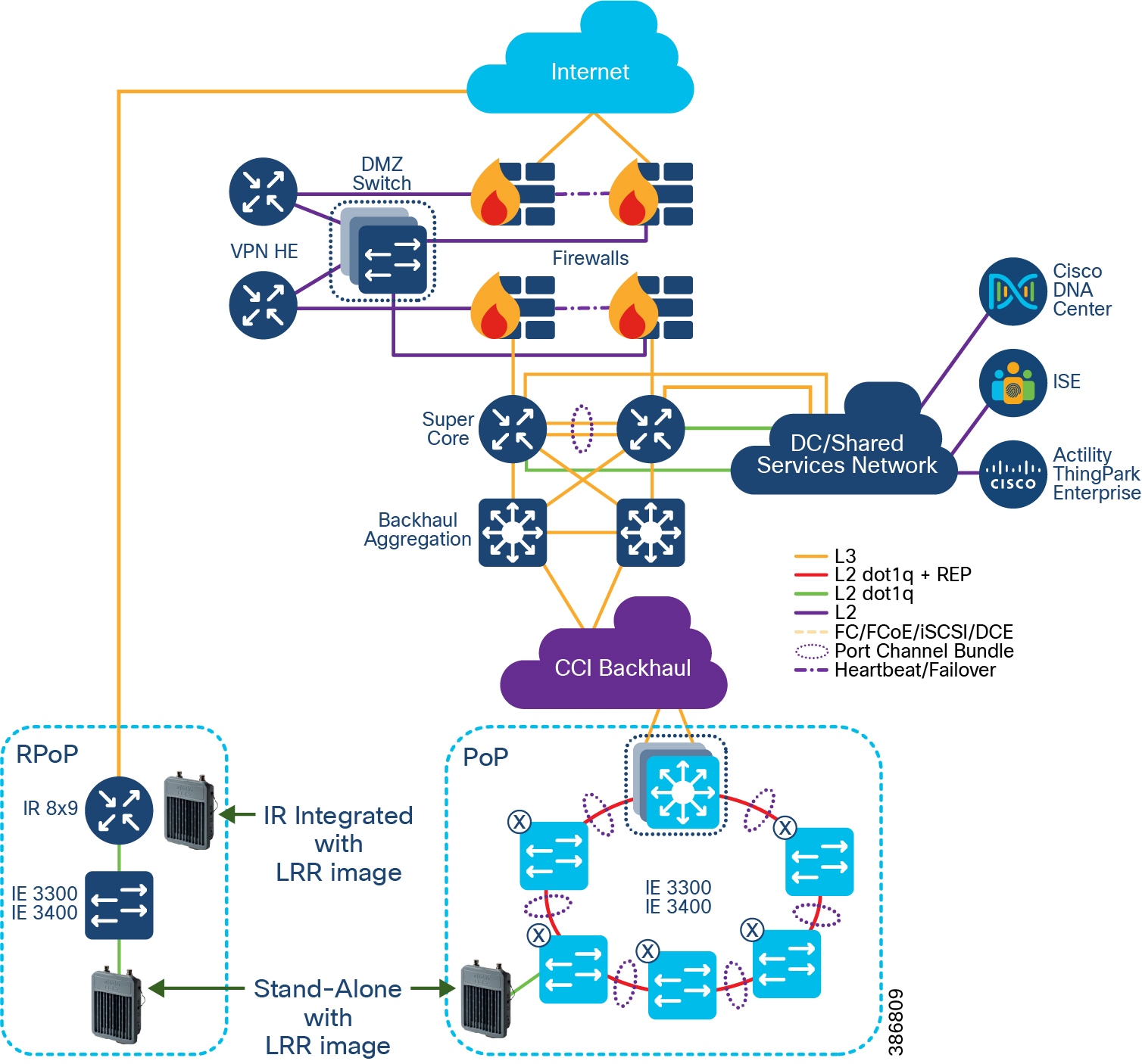
Data Flow from Internal PoPs (Flow A)
- Cisco Wireless Gateway for LoRaWAN is connected to Cisco Industrial Ethernet (IE) switches in a REP ring at PoPs.
- The TPE server resides in the Data Center.
- A Cisco Wireless Gateway for LoRaWAN receives sensor data from LoRaWAN devices, then forwards to the TPE server at the Data Center through the transit network in the SD-Access fabric.
- If the message has application payload, TPE prepares the message and puts it into the connector appropriate for the Application Server in the cloud.
Data Flow from Remote PoPs (Flow B)
- Cisco Wireless Gateway for LoRaWAN gateways are connected with Cisco IR809/IR829/IR1101 for cellular backhaul in standalone mode in an R-PoP (i.e., the gateway works in standalone or integrated mode to leverage IR809/IR829/IR1101 router for cellular backhaul).
- The Cisco IR809/IR829/IR1101 establishes a VPN tunnel with the HE router residing in the DMZ.
- The Actility TPE server resides in the Data Center.
- A Cisco Wireless Gateway for LoRaWAN receives sensor data from LoRaWAN devices. It sends data to the data center through the cellular backhaul encapsulated within the secure VPN tunnel.
The headend router de-encapsulates the message from the VPN tunnel and forwards it to the destination IP, under the condition the firewall allows the traffic to go through.
LoRaWAN device addition via Actility management portal
Adding a new device to Actility:
Step 1: Open the Actility management interface and select Device:Create – LoRaWAN Generic
Step 2: Add device information
–![]() Associate your sensor to the appropriate application for data streaming
Associate your sensor to the appropriate application for data streaming
Step 3: Device add confirmation
LoRaWAN deployment guidance
Wireless signals can be impacted by interference in the spectrum as well as obstacles that exist in the real world. In this regard, LoRaWAN is no different than other wireless technologies. A proper site survey should be completed prior to the installation, verification should be done after installation, and ongoing periodic checks of the wireless health of the area should be continued for the life the installation.
Cisco has created the following document to provide basic guidance for outdoor LoRaWAN installations: https://salesconnect.cisco.com/open.html?c=27f90a9a-f7c7-4c6d-9020-8fd5b9cd0025
Note: the above URL can only be accessed by Cisco Employees/Sales and Partners who has Cisco user account. Please work with your Cisco sales or partner team to gain access to this URL.
Shared Network Services
This chapter includes the following major topics:
- Next-Generation Firewall (NGFW) and DMZ Network
- Common Infrastructure and Services
- Security Architecture and Design Considerations
- Network QoS Design
- Multicast Network Traffic Design
- Network Visibility and Threat Defense using Cisco Secure Network Analytics
- CCI Network Scale and Dimensioning
Next-Generation Firewall (NGFW) and DMZ Network
A DMZ in the CCI infrastructure provides a layer of security for the internal network by terminating externally-connected services from the Internet and Cloud at the DMZ and allowing only permitted services to reach the internal network nodes.
Any network service that runs as a server requiring communication to an external network or the Internet are candidates for placement in the DMZ. Alternatively, these servers can be placed at the data center and be only reachable from the external network after being quarantined at DMZ.
The DMZ in the CCI architecture is where headend routers (e.g., Cisco Cloud Services Router 1000V) reside that are used to terminate VPN tunnels from external network. DMZ Design in CCI Architecture Dual-Layer Firewall Model illustrates the DMZ design with dual-firewall in CCI:
Figure 57 DMZ Design in CCI Architecture Dual-Layer Firewall Model
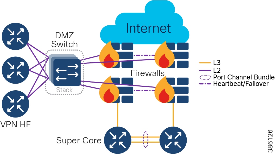
In DMZ Design in CCI Architecture Dual-Layer Firewall Model, the DMZ is protected by two firewalls (with redundancy) and the external network-facing firewall (perimeter firewall) is set up to allow traffic to pass to the DMZ only. For example, in CCI, FlexVPN traffic (UDP port 500 and 4500) is allowed. The internal network-facing firewall (internal firewall) is set up to allow certain traffic from the DMZ to the internal network.
The dual-firewall model of DMZ design allows for the creation of two distinct and independent points of control for all traffic into and out of all internal network. No traffic from the external network is permitted directly to the internal network. Some implementations suggest adoption of two different firewall models by two different vendors to reduce the likelihood of compromise because of the low probability of the same security vulnerability existing on both firewalls. Because of the cost and complexity of the dual-firewall architecture, it is typically implemented in environments with critical security requirements such as banking, government, finance, and larger medical organizations.
Alternatively, a three-legged model of DMZ design uses a single firewall (with redundancy) with a minimum of three network interfaces to separate the external network, internal network, and DMZ.
Figure 58 DMZ Design in CCI Architecture Single-Layer Firewall Model
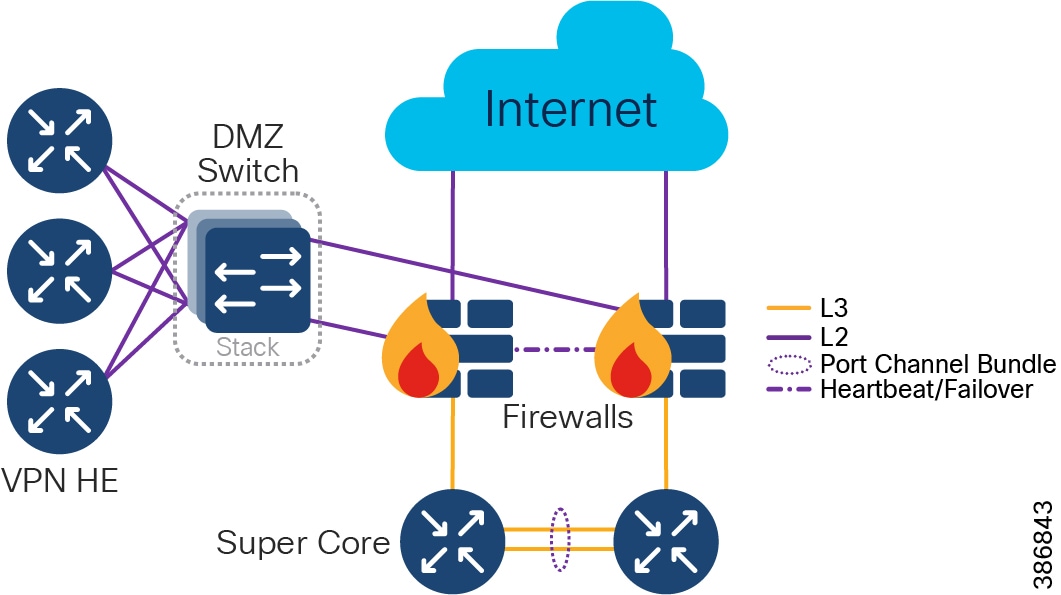
Several headend routers are placed in the DMZ to terminate the FlexVPN tunnels. The recommended platform is Cisco Cloud Services Router 1000V; the dimension is based on the number and type of VPN clients expected to connect to the CCI infrastructure.
Traditional stateful firewalls with simple packet filtering capabilities efficiently blocked unwanted applications because most applications met the port-protocol expectations. However, in today's environment, protection based on ports, protocols, or IP addresses is no longer reliable or workable. This fact led to the development of an identity-based security approach, which takes organizations a step beyond conventional security appliances that bind security to IP addresses.
NGFW technology offers application awareness that provide system administrators a deeper and more granular view of network traffic in their systems. The level of information detail provided by NGFW can help with both security and bandwidth control.
Cisco NGFW (Firepower appliance) resides at the network edge to protect network traffic from the external network. In the CCI design, a pair of Firepower appliances (Firepower 2140) are deployed as active/standby units for high availability. The Firepower units have to be the same model with the same number and types of interfaces running the exact same software release. On the software configuration side, the two units have to be in the same firewall mode (routed or transparent) and have the same Network Time Protocol (NTP) configuration.
The two units communicate over a failover link to check each other's operational status. Failovers trigger by events such as the primary unit losing power, primary unit interface link physical down, or primary unit physical link up but has connection issue. During a stateful failover, the primary unit continually passes per-connection state information to the secondary unit. After a failover occurs, the same connection information is available at the new primary unit. Supported end-user applications (i.e., TCP/UDP connections and states, SIP signaling sessions) are not required to reconnect to keep the same communication session.
For more details, refer to the Firepower documentation at the following URL:
https://www.cisco.com/c/en/us/td/docs/security/firepower/70/configuration/guide/fpmc-config-guide-v70/high_availability_for_firepower_threat_defense.html
The CCI Network architecture or CCI vertical use cases leverages the following Cisco NGFW features:
–![]() These include the traditional firewall functionalities such as stateful port/protocol inspection, Network Address Translation (NAT), and Virtual Private Network (VPN).
These include the traditional firewall functionalities such as stateful port/protocol inspection, Network Address Translation (NAT), and Virtual Private Network (VPN).
–![]() This is to set access control rules to filter traffic based on the URL used in an HTTP or HTTPS connection. Since HTTPS traffic is encrypted, consider setting SSL decryption policies to decrypt all HTTPS traffic that the NGFW intends to filter.
This is to set access control rules to filter traffic based on the URL used in an HTTP or HTTPS connection. Since HTTPS traffic is encrypted, consider setting SSL decryption policies to decrypt all HTTPS traffic that the NGFW intends to filter.
–![]() Discover network traffic with application-level insight with deep packet visibility into web traffic.
Discover network traffic with application-level insight with deep packet visibility into web traffic.
–![]() Analyze and monitor application usages and anomalies.
Analyze and monitor application usages and anomalies.
–![]() Build reporting for capacity planning and compliance.
Build reporting for capacity planning and compliance.
–![]() Collected and analyzed data includes information about applications, users, devices, operating systems, and vulnerabilities.
Collected and analyzed data includes information about applications, users, devices, operating systems, and vulnerabilities.
–![]() Build network maps and host profiles to provide contextual information.
Build network maps and host profiles to provide contextual information.
–![]() Security automation correlates intrusion events with network vulnerabilities.
Security automation correlates intrusion events with network vulnerabilities.
–![]() Network weaknesses are analyzed and automatically generate recommended security policies to put in place to address vulnerabilities.
Network weaknesses are analyzed and automatically generate recommended security policies to put in place to address vulnerabilities.
–![]() Collects global threat intelligence feeds to strengthen defenses and protect against known and emerging threats.
Collects global threat intelligence feeds to strengthen defenses and protect against known and emerging threats.
–![]() Uses that intelligence coupled with known file signatures to identify and block policy-violating file types and exploit attempts and malicious files trying to infiltrate the network.
Uses that intelligence coupled with known file signatures to identify and block policy-violating file types and exploit attempts and malicious files trying to infiltrate the network.
–![]() Upon detection of threats, instantly alert security teams with an indication of compromise and detail in-formation of malware origin, system impacted, and what the malware does.
Upon detection of threats, instantly alert security teams with an indication of compromise and detail in-formation of malware origin, system impacted, and what the malware does.
–![]() Update the global threat intelligence database with new information.
Update the global threat intelligence database with new information.
Common Infrastructure and Services
This section covers various common Infrastructure components and shared services in the CCI Network.
Shared services, as the name indicates, are a common set of resources for the entire network that are accessible by devices/clients across all VNs and SGTS. Shared services are kept outside the fabric domain(s). Communication between shared services and the fabric VN/SGTs are selectively enabled by appropriate route leaking at the fusion router. Usually shared services are located at a central location. Major shared services of the CCI network include DNA Center, ISE, DHCP, DNS, FND, and NGFW.
Cisco DNA Center
The Cisco Digital Network Architecture Center (Cisco DNA Center) is an open and extensible management platform for the entire CCI Network solution to implement intent-based networking. It also provides network automation, assurance, and orchestration.
Cisco DNA Center with SD-Access enables management of a large-scale network of thousands of devices. It can configure and provision thousands of network devices across the CCI network in minutes, not hours or days.
The major concerns for a large network such as CCI are security, service assurance, automation, and visibility. These requirements are to be guided by the overall CCI network intent. Cisco DNA Center with SD-Access enables all these functionalities in an automated, user-friendly manner.
Cisco DNA Center Appliance
The Cisco DNA Center software application package is designed to run on the Cisco DNA Center Appliance, configured as a cluster. The Cisco DNA Center cluster is accessed using a single GUI interface hosted on a virtual IP, which is serviced by the resilient nodes within the cluster.
Identity Services Engine (ISE)
The Cisco Identity Services Engine (ISE) is a policy-based access control system that enables enterprises, Smart Cities, and alike to enforce compliance, enhance infrastructure security, and streamline their service operations.
The Cisco ISE consists of several components with different ISE personas:
–![]() Single pane of glass for ISE admin
Single pane of glass for ISE admin
–![]() Replication hub for all database configuration changes
Replication hub for all database configuration changes
–![]() Syslog collector for ISE nodes
Syslog collector for ISE nodes
–![]() Facilitates sharing of context
Facilitates sharing of context
In the CCI architecture, ISE is deployed centralized in the standalone mode together with the Cisco DNA Center (in the Shared Services segment) with redundancy. Optionally, distributed PSNs can be deployed within fabric sites and in CCI PoP and RPoPs to provide faster response time.
Depending on the size of the deployment, all personas can be run on the same device (standalone mode) or spread across multiple devices (multi-node ISE) for redundancy and scalability. The detailed scaling information and limits for ISE can be found at the following URL:
ISE integrates with the Cisco DNA Center via the Platform eXchange Grid (pxGrid) interface to enable network-wide context sharing. pxGrid is a common method for network and security platform to share data about devices through a secure publish-and-subscribe mechanism. A pxGrid subscriber registers to PXG to subscribe to “topic” information. A pxGrid Publisher publishes topics of information to PXG and pxGrid Subscriber receives the topic information once it is available. Examples of “topics” include:
- TrustSecMetaData—Provides pxGrid clients with exposed scalable group tag (SGT) information
- EndpointProfileMetaData—Provides pxGrid clients with available device information from ISE
- SessionDirectory—Session directory table
The main roles of ISE in the CCI infrastructure is to authenticate devices, perform device classification, authorize access based on policy, and support SGT tag propagation.
–![]() Classifies a device based on the device profile information gathered. For example, detect a device plugged in matches IP Camera profile and assign the device to the video VLAN.
Classifies a device based on the device profile information gathered. For example, detect a device plugged in matches IP Camera profile and assign the device to the video VLAN.
- Performs 802.1X or MAC Address Bypass (MAB) for devices connected to nodes attached to the access switches in the PoP ring.
- Currently an access port on extended node is automated from the Cisco DNA Center with a pre-defined service VLAN. A trunk between the extended node and fabric edge carries all the VLAN's traffic. The recommended method is to do VLAN-to-SGT binding statically at the fabric edge for device classification. This can be automated via the Cisco DNA Center.
- Access authorization:
–![]() The PSN will authorize device access capability based on the policy defined for the class of devices.
The PSN will authorize device access capability based on the policy defined for the class of devices.
–![]() SGT tag information shall be propagated from one fabric site to another to maintain consistent end-to-end policy throughout the network.
SGT tag information shall be propagated from one fabric site to another to maintain consistent end-to-end policy throughout the network.
–![]() However, packets that transport over nodes that don't support VXLAN or that don't have inline tagging capability will lose SGT tagging information.
However, packets that transport over nodes that don't support VXLAN or that don't have inline tagging capability will lose SGT tagging information.
- SGT eXchange Protocol (SXP)
- As SGT Tag Propagation via SXP shows, “Router A” has no inline capability. Any SGT tag from “Switch A” to “Router B” will not be carried over because “Router A” is not inline capable.
- In order to restore the SGT tag at “Router B,” leverage the SXP protocol where the “Switch A” is the speaker and “Router B” is the listener.
- The SXP protocol sends the SGT tag (5) assigned to the end device (IP 10.0.1.2) from “Switch A” to “Router B.”
- The SXP protocol uses TCP as the transport protocol over TCP port 64999.
- Cisco ISE can be an SXP speaker/listener. It is recommended to establish SXP from Fabric Border to ISE for ease of configuration.
- A list of Cisco switches and routers support SXP can be found at the following URL:
–![]() https://www.cisco.com/c/dam/en/us/solutions/collateral/enterprise-networks/trustsec/6-5-gbp-platform-capability-matrix.pdf
https://www.cisco.com/c/dam/en/us/solutions/collateral/enterprise-networks/trustsec/6-5-gbp-platform-capability-matrix.pdf
Figure 59 SGT Tag Propagation via SXP
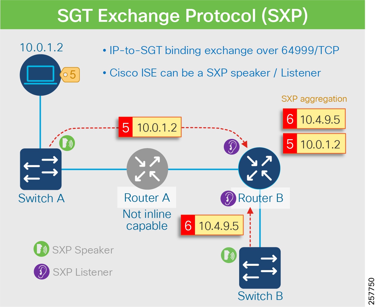
–![]() As described in Identity Services Engine (ISE), ISE and the Cisco DNA Center are integrated using pxGrid to share users and device contexture information.
As described in Identity Services Engine (ISE), ISE and the Cisco DNA Center are integrated using pxGrid to share users and device contexture information.
–![]() Besides the Cisco DNA Center, a number of Cisco and third-party products have integrated with pxGrid based on the Cisco published integration guide. More details can be found at the following URL:
Besides the Cisco DNA Center, a number of Cisco and third-party products have integrated with pxGrid based on the Cisco published integration guide. More details can be found at the following URL:
- https://community.cisco.com/t5/security-documents/ise-security-ecosystem-integration-guides/ta-p/3621164
–![]() In the CCI infrastructure, the pxGrid can integrate ISE with CyberVision to improve network visibility.
In the CCI infrastructure, the pxGrid can integrate ISE with CyberVision to improve network visibility.
Once the SGT is propagated, it can be carried to the policy enforcement node for access control decisions.
ISE and Cisco DNA Center in SD-Access illustrates the interworking of each component of ISE and the Cisco DNA Center:
Figure 60 ISE and Cisco DNA Center in SD-Access
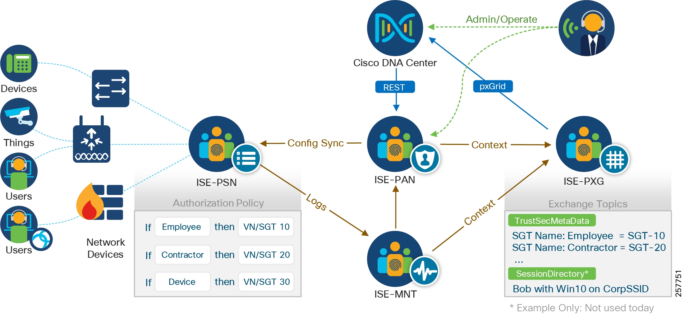
Application Servers Network
Application servers are dedicated for specific services; for example, Video Surveillance Manager (VSM) is dedicated for video services management. Only the devices and users having access to the specific service should be able to communicate with the application server. In the case of VSM, the cameras, media servers, and users having video access can communicate with the VSM server.
In the case of a fabric-supported network, this is achieved by placing the application servers in one of the fabric sites. The application servers are connected to a Nexus switch behind the Fabric Edge. The access port on the FE/FiaB is configured as a Server Port. Appropriate Subnets and VLANs are configured on the Nexus ports connecting the application servers that match the respective service Subnet/VLAN auto allocated by the Cisco DNA Center. In the Fabric Site, the desired VNs, Subnets, and Static SGTs are configured matching various services. As the application servers and corresponding clients are assigned, the same SGT and VN access is provided. Any other service that is part of the same VN, but is of a different SGT, will require appropriate group-based access policy for communication. In an exception case, if a device/client of one VN needs access to the application server of a different VN, appropriate route leaking needs to be done at the FR in order for it to become accessible.
Field Network Director (FND)
The Cisco FND is a software platform that can monitor and manage several solutions including IR8x9/1101 routers, and CR-Mesh and LoRaWAN access network solution. It provides enhanced fault, configuration, accounting, performance, and security (FCAPS) capabilities for highly scalable and distributed systems such as smart street lighting controllers and power meters.
Additional capabilities of the FND are:
- Zero Touch Deployment for CGRs, IR8x9, IR1101 and IXM gateways
- Network topology visualization and integration with existing Geological Information System (GIS)
- Simple, consistent, and scalable network layer security policy management and auditing
- Extensive network communication troubleshooting tools
- Northbound APIs are provided for integration with third party applications
- Third party device management with IoT Device Agent (IDA)
FND provides the necessary backend infrastructure for policy management, network configuration, monitoring, event notification services, network stack firmware upgrade, Connected Grid Endpoint (CGE) registration, and maintaining FAR and CGE inventory. FND uses a database that stores all the information managed by the FND. This includes all metrics received from mesh endpoints, and all device properties, firmware images, configuration templates, logs, and event information.
For more information on using FND, refer to the latest version of Cisco IoT Field Network Director User Guide at the following URL:
Network Time Protocol (NTP) Server
Certain services running within the CCI network require accurate time synchronization between the network elements. Many of these applications process a time-ordered sequence of events, so the events must be time stamped to a level of precision that allows individual events to be distinguished from one another and correctly ordered. A Network Time Protocol (NTP) version 4 server running over the IPv4 and IPv6 network layer can act as a Stratum 1 timing source for the network.
Applications that require time stamping or precise synchronization include:
Cisco Prime Network Registrar (CPNR)
Cisco Prime Network Registrar (CPNR) provides integrated, scalable, and reliable Domain Name System (DNS), Dynamic Host Configuration Protocol (DHCP), and IP Address Management (IPAM) services for both IPv4 and IPv6. DHCPv6 is the desired address allocation mechanism for highly scalable outdoor systems consisting of many endpoints, as an example CGE mesh endpoints for streetlights or energy meters.
CPNR is a full featured, scalable DNS, DHCP, and Trivial File Transfer Protocol (TFTP) implementation for medium-to-large IP networks. It provides the key benefits of stabilizing the IP infrastructure and automating networking services, such as configuring clients and provisioning cable modems. This provides a foundation for policy-based networking.
A DHCP Server is a network server that dynamically assigns IPv4 or IPv6 addresses, default gateways, and other network parameters to client devices. It relies on the standard protocol known as DHCP to respond to broadcast queries by clients. This automated IP address allocation help IP planning and avoid manual IP configuration to network devices and clients.
The DNS service is a hierarchical and decentralized service for translating domain names to the numerical IP addresses.
Headend Routers (HER)
The primary function of a HER is to aggregate the WAN connections coming from the field-deployed devices, including Connected Grid Routers, Cisco 809 Industrial Integrated Services Routers, and Cisco 829 Industrial Integrated Services Router, and Cisco IR1101 Integrated Services Router Rugged. A HER can be a dedicated hardware appliance or a hosted CSR 1000v. The HER terminates the FlexVPN IPSec and GRE tunnels. HER may also enforce QoS, profiling (Flexible NetFlow), and security policies.
Multiple Cisco CSR 1000V routers can be configured in clusters for redundancy and to facilitate increased scalability of tunnels. In the case of a cluster configuration, a single CSR acts as the primary and load balances the incoming traffic among the other HERs. Alternately, the Hot Standby Router Protocol (HSRP) can be configured for active/standby redundancy.
HER HA design outlined in the Distributed Automation Design Guide - https://www.cisco.com/c/en/us/td/docs/solutions/Verticals/Distributed-Automation/Secondary-Substation/DG/DA-SS-DG.html
Authentication, Authorization, and Accounting (AAA)
A framework for intelligently controlling access to computer resources, enforcing policies, auditing usage, and providing the information necessary to bill for services.
Remote Authentication Dial-In User Service (RADIUS)
RADIUS is a networking protocol, operating on Port 1812 that provides centralized authentication, authorization, and accounting management for users who connect and use a network service.
Public Key Infrastructure (PKI)
A Public Key Infrastructure (PKI) supports the distribution, revocation and verification of public keys used for public key encryption and enables linking of identities with public key certificates. It enables users and systems to securely exchange data over the network and verify the legitimacy of certificate-holding entities, such as servers, endpoints, and individuals. The PKI enables users to authenticate digital certificate holders, as well as to mediate the process of certificate revocation, using cryptographic algorithms to secure the process.
Certificate Authority
The Certificate Authority (CA) is part of a public key infrastructure and is responsible for generating or revoking digital certificates assigned to the devices and mesh endpoints. The CAs are unconditionally trusted and are the root of all certificate chains.
RSA Certification Authority
An RSA Certificate Authority (RSA CA) provides signed certificates to network components such as routers and servers like FND.
ECC Certification Authority
The Elliptic Curve Cryptography Certificate Authority (ECC CA) provides signed certificates for endpoint devices like power meters and street lighting controllers.
Cisco Wireless LAN Controller (WLC)
Cisco WLCs may be located in the Shared Services segment, or as part of PoP distribution infrastructure. A high-level summary of steps for manual provisioning of the PEN ring is explained below. Refer to the CCI Implementation Guide for detailed step-by-step instructions for configuring PEN ring for details on location.
The WLC role is to be in control of Cisco Lightweight APs, using the CAPWAP protocol (Control and Provisioning of Wireless Access Points); managing software versions and settings, handoff of traffic at the edge, or tunneling of traffic back to the WLC.
WLCs may be appliances or embedded as software components in another Cisco networking device. Deploying WLCs as HA pairs is recommended.
Cisco Prime Infrastructure
Cisco Prime Infrastructure (PI) is used for management of a Cisco Unified Wireless Network (CUWN) Mesh. Although PI is capable of performing network management for other devices and systems within CCI, its role in CCI 2.1 is limited to just the Wi-Fi Mesh – DNAC being used for everything else.
Cisco DNA Spaces
Cisco DNA Spaces is a location services platform, delivered as a cloud-based service. Wireless LAN Controllers (WLCs) integrate with DNA Spaces, and as such must have an outbound path to the Public Internet.
DNA Spaces generates Wi-Fi client computed location, tracking and analytics, with visualization and the ability to export all this data; also provides captive portal, hyper-location, advanced analytics and API/SDK integration possibilities.
Security Architecture and Design Considerations
This section includes the following major topics:
- Security Segmentation Design
- Network Visibility and Threat Defense using Cisco Secure Network Analytics
- Secure Connectivity
- Advantages of Network Segmentation
Security Segmentation Design
Network segmentation is the practice of dividing a larger network into several small sub-networks that are isolated from one another.
Advantages of Network Segmentation
- Improved Security—Network traffic can be segregated to prevent access between network segments.
- Better Access Control—Allows users to only access specific network resources.
- Improved Monitoring—Provides an opportunity to log events, monitor allowed and denied internal connections, and detect suspicious behavior.
- Improved Performance—With fewer hosts per subnet, local traffic is minimized. Broadcast traffic can be isolated to the local subnet.
- Better Containment—When a network issue occurs, its effects are limited to the local subnet.
In the SD-Access environment, fabric uses LISP as the control plane and VXLAN for the data plane (as mentioned earlier in this guide, the intricacies of LISP and VXLAN are hidden from the administrator, as SD-Access automates both as part of VNs).
–![]() Endpoints register to the fabric edge, obtain an EID
Endpoints register to the fabric edge, obtain an EID
–![]() Fabric edge places the EID into the Host Tracking Database (HTDB)
Fabric edge places the EID into the Host Tracking Database (HTDB)
–![]() Control Plane node resolves EID to RLOC mappings
Control Plane node resolves EID to RLOC mappings
–![]() Control plane node provides default gateway when no mapping exists
Control plane node provides default gateway when no mapping exists
–![]() VXLAN header includes VN information (24 bit VN index called VNI)
VXLAN header includes VN information (24 bit VN index called VNI)
–![]() VXLAN header also includes Scalable Group (SG) information (16 bit SG tag called SGT)
VXLAN header also includes Scalable Group (SG) information (16 bit SG tag called SGT)
Traffic segmentation in SD-Access are accomplished through the following:
–![]() Control plane by LISP uses VN ID to maintain separate VRF topologies
Control plane by LISP uses VN ID to maintain separate VRF topologies
–![]() Each VN instance maintains a separate routing table to ensure no communication takes place between one VN with another
Each VN instance maintains a separate routing table to ensure no communication takes place between one VN with another
–![]() Scalable policies (SGACL) are defined
Scalable policies (SGACL) are defined
–![]() Policy enforcement nodes request policies relevant to them
Policy enforcement nodes request policies relevant to them
–![]() ISE classification associates a device with an SGT when a device is detected in the network
ISE classification associates a device with an SGT when a device is detected in the network
–![]() SGT is encapsulated in the VXLAN header of the packet associated with the device traffic
SGT is encapsulated in the VXLAN header of the packet associated with the device traffic
–![]() SGT is propagated from one fabric node to another when traffic from a device traverses the network
SGT is propagated from one fabric node to another when traffic from a device traverses the network
–![]() Policy enforcement nodes enforce Security Group ACL (SGACL) policies
Policy enforcement nodes enforce Security Group ACL (SGACL) policies
- New User/Device/Server provisioned
- Switch requests policies for assets they protect
- Policies are downloaded and applied dynamically
- Result: All controls centrally managed:
–![]() Security policies de-coupled from network topology
Security policies de-coupled from network topology
–![]() No switch-specific security configs needed
No switch-specific security configs needed
–![]() One place to audit network-wide policies
One place to audit network-wide policies
A Virtual Network can be defined by an access technology such that, for example, V2X traffic will not be mixed with LoRaWAN traffic, but a VN can also be defined across access technologies. In each VN, Security Groups can be identified, and access control policy can be enforced. Following section describes micro-segmentation in detail.
Micro Segmentation Design in Ethernet Access Ring
The CCI security design also supports micro-segmentation for securing traffic flow within a VN in CCI network. Endpoints connected to the access rings can be configured to allow access only to specific services/servers in the HQ/DC site also known as South-to-North traffic flow and vice-versa in CCI network. The traffic within endpoints connected to a given ring is defined as East-to-West traffic or vice-versa depending on the source and destination traffic flow.
In the CCI architecture, SGACL policies are enforced at destination Fabric Edge/FiaB for the South-to-North traffic (endpoints to server in DC). Server to endpoints/device communication (North-to-South) traffic (if any required) SGACL polices can be defined and enforced on destination Fabric Edge/FiaB.
See Micro-segmentation enforcement for Extended Node and Policy Extended Node rings for an example of micro-segmentation enforcement deployed in Extended Node and Policy Extended Node rings.
Table 16 Micro-segmentation enforcement for Extended Node and Policy Extended Node rings
In cases where there are Ethernet access rings with a mixture of IE4000 and/or IE5000 and/or IE3300 series switches, all micro-segmentation policy enforcement is done at Fabric Edge/FiaB on such mixed switches rings. Refer to Comparison of Extended Node and Policy Extended Node features, for a detailed feature comparison of EN and PEN switches.
Note that micro-segmentation of South-to-North and North-to-South traffic is supported in Extended Nodes Ring in CCI PoP. East-to-West and West-to-East traffic enforcement for the endpoints connected within EN is not supported. It is recommended to deploy Policy Extended Nodes ring, discussed in the next section, for the East-to-West or West-to-East traffic enforcement within the access ring.
Micro Segmentation Design in Policy Extended Nodes Ring
An Ethernet access ring consisting of Policy Extended Nodes (aka PEN ring) supports micro-segmentation using Scalable Group Tags (SGT) and SGACL device to device communication policies. Endpoints connected to Policy Extended Nodes ring download the right VLAN and SGT attributes from Cisco ISE upon successful authentication and authorization by ISE, so that device to device communication polices for micro segmenting the traffic can be defined and enforced on the Policy Extended Node.
In the ring of PENs, East to West and vice versa traffic SGACL policies can be defined and enforced on destination PEN, as shown in CCI Micro Segmentation Design in Policy Extended Node Ring. Note that, the SGACL policy enforcement always happens at the destination switch in the ring. It is recommended to deploy PEN rings for use cases where East-to-West and vice-versa traffic enforcement is needed within the access ring.
The PEN ring must be configured with all IE3400 (PEN capable) switches with DNA Advantage and Network Advantage licensing. The PEN ring is configured as one Gigabit Ethernet Access ring as shown in CCI Micro Segmentation Design in Policy Extended Node Ring, for the successful configuration of CTS commands and SGACL policies within the ring.
Figure 61 CCI Micro Segmentation Design in Policy Extended Node Ring
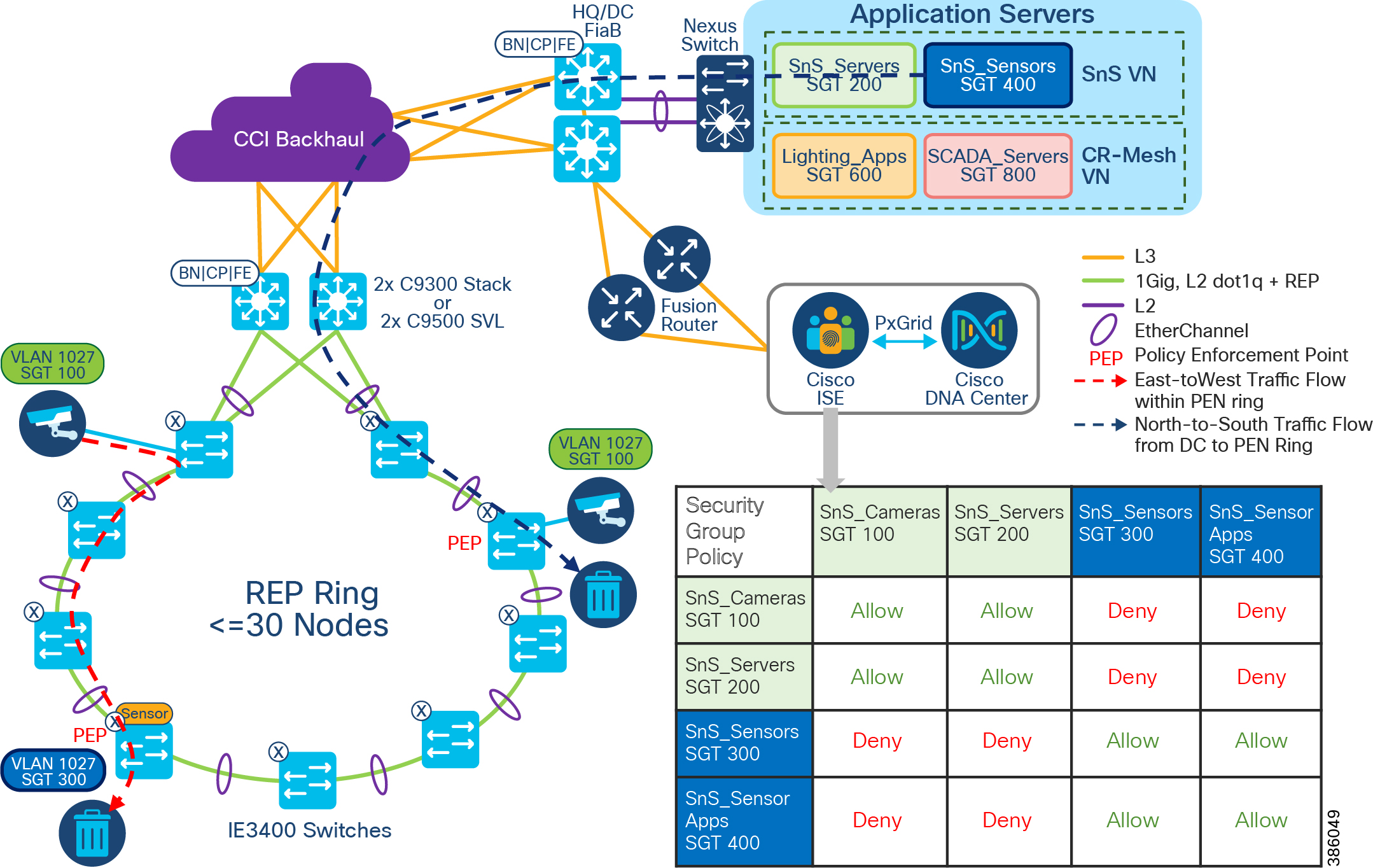
As shown in CCI Micro Segmentation Design in Policy Extended Node Ring, there is an SGACL policy matrix on ISE is created (either directly on ISE or in Cisco DNA Center), which denies the traffic between SGT100, SGT200 and SGT 300, SGT 400. All other communication between these SGTs are allowed. This SGACL policy is enforced on destination PEN in the ring to which the SnS sensor device is connected. An SnS IP Camera (SGT 100) is trying to communicate with the SnS Sensor (SGT 300). Such East-to-West traffic in the PEN ring is denied and traffic is dropped at PEN.
Also, in this example, North-to-South traffic from SnS sensor applications (SGT400) in DC site to an SnS IP Camera (SGT 100) connected to a PEN in the ring is denied. All such traffic is dropped at destination PEN in the ring on which the micro segmentation policy is enforced.
Note: Policy is enforced (such as SGACL permit or deny) on the destination port.
Note: Although Cisco DNA Center UI allows the administrator to build out a policy matrix, this policy may not be enforced in the case of Extended Nodes, depending on where the source and destination devices are connected. If both devices are connected within the same access ring, and this ring is comprised of Extended Nodes, then traffic between these devices has policy enforced only if that traffic passes through the FiaB.
SGT Derivation and Propagation in a Network with IP Transit and SD-Access Transit
As discussed earlier, micro-segmentation within a VN is achieved with the help of Security Groups represented by SGT. The micro-segmentation policy is defined by SGACL. For policy enforcement, both source and destination SGTs are derived and SGACLs are applied. The source fabric edge derives the source SGT from binding information. In the case of IP transit, SXP configuration needs to be done manually on the fabric edge to retrieve SGT binding information from ISE. In case of SD-Access transit, SXP is not needed as the system automates configuration at the fabric edge to retrieve SGT binding information from ISE.
Propagation of SGT information also differs between IP and SD-Access transit. In the case of SD-Access transit, the SGTs are propagated from the source fabric to the destination fabric through inline tagging within the VXLAN header.
In the case of IP transit, inline tagging (VXLAN header) is not supported and SGT tags are lost at the fabric border. The destination fabric needs to derive both source SGT and destination SGT from the binding information, obtained from ISE using SXP.
Network Visibility and Threat Defense using Cisco Secure Network Analytics
Network visibility is the foundation for continuous monitoring to gain awareness of what is happening in the network. Complete visibility is critical to making proactive decisions and getting to resolutions as quickly as possible. Network threat defense is for preventing threats from the external network entering the internal network or to identify suspicious network traffic patterns within the network.
Cisco Secure Network Analytics Enterprise (formerly Cisco Stealthwatch) provides network visibility and applies advanced security analytics to detect and respond to threats in real time. Using a combination of behavioral modeling, machine learning, and global threat intelligence, Cisco Secure Network Analytics Enterprise can quickly, and with high confidence, detect threats such as command-and-control (C&C) attacks, ransomware, DDoS attacks, illicit cryptomining, unknown malware, and insider threats. With a single, agentless solution, you get comprehensive threat monitoring across the entire network traffic, even if it is encrypted.
Cisco Secure Network Analytics enlists the network to provide end-to-end visibility of traffic. This visibility includes knowing every host—seeing who is accessing which information at any given point. From there, it is important to know what normal behavior for a particular user or “host” is and establish a baseline from which you can be alerted to any change in the user's behavior the instant it happens.
Cisco Secure Network Analytics offers many advantages when deployed, including:
- Network Visibility —Cisco Secure Network Analytics is the security analytics solution that can provide comprehensive visibility in the private network as well as the public cloud and without deploying sensors everywhere.
- Threat Detection - Cisco Secure Network Analytics is constantly monitoring the network in order to detect advanced threats in real time. Using the power of behavioral modeling, multi-layered machine learning, and global threat intelligence, Cisco Secure Network Analytics reduces false positives and alarms on critical threats affecting your environment.
- Incident Response/Threat Defense – Protects network and critical data with smarter and effective network segmentation. Using the Secure Network Analytics integration with Cisco Identity Services Engine (ISE) to create and enforce policies, and keep unauthorized users and devices from accessing restricted areas of the network.
Flexible NetFlow Data Collection
NetFlow is a network protocol system created by Cisco that collects active IP network traffic as it flows in or out of an interface. NetFlow is now part of the Internet Engineering Task Force (IETF) standard (RFC 3954) as Internet Protocol Flow Information eXport (IPFIX, which is based on NetFlow Version 9 implementation), and the protocol is widely implemented by network equipment vendors.
NetFlow is an embedded instrumentation within Cisco IOS Software to characterize network operation. Visibility into the network is an indispensable tool for IT professionals. NetFlow is a protocol that creates flow records for the packets flowing through the switches and the routers in a network between the end devices and exports the flow records to a flow collector. The data collected by the flow collector is used by different applications to provide further analysis. In CCI, NetFlow is primarily used for providing security analysis, such as malware detection, network anomalies, and so on.
The Cisco Industrial Ethernet (IE) 3400, Cisco IE 3300, Cisco IE 4000, Cisco IE 4010, Cisco IE 5000, Cisco Catalyst 9300, and Cisco Catalyst 9500 support full Flexible NetFlow. Each packet that is forwarded within a router or switch is examined for a set of IP packet attributes. These attributes are the IP packet identity or fingerprint of the packet and determine if the packet is unique or similar to other packets.
Traditionally, an IP Flow is based on a set of 5 and up to 7 IP packet attributes, as shown in CCI NetFlow Data Collection. All packets with the same source/destination IP address, source/destination ports, protocol interface and class of service are grouped into a flow and then packets, and bytes are tallied. This methodology of fingerprinting or determining a flow is scalable because a large amount of network information is condensed into a database of NetFlow information called the NetFlow cache.
With the latest releases of NetFlow v9, the switch or router can gather additional information such as ToS, source MAC address, destination MAC address, interface input, interface output, and so on.
Figure 62 CCI NetFlow Data Collection
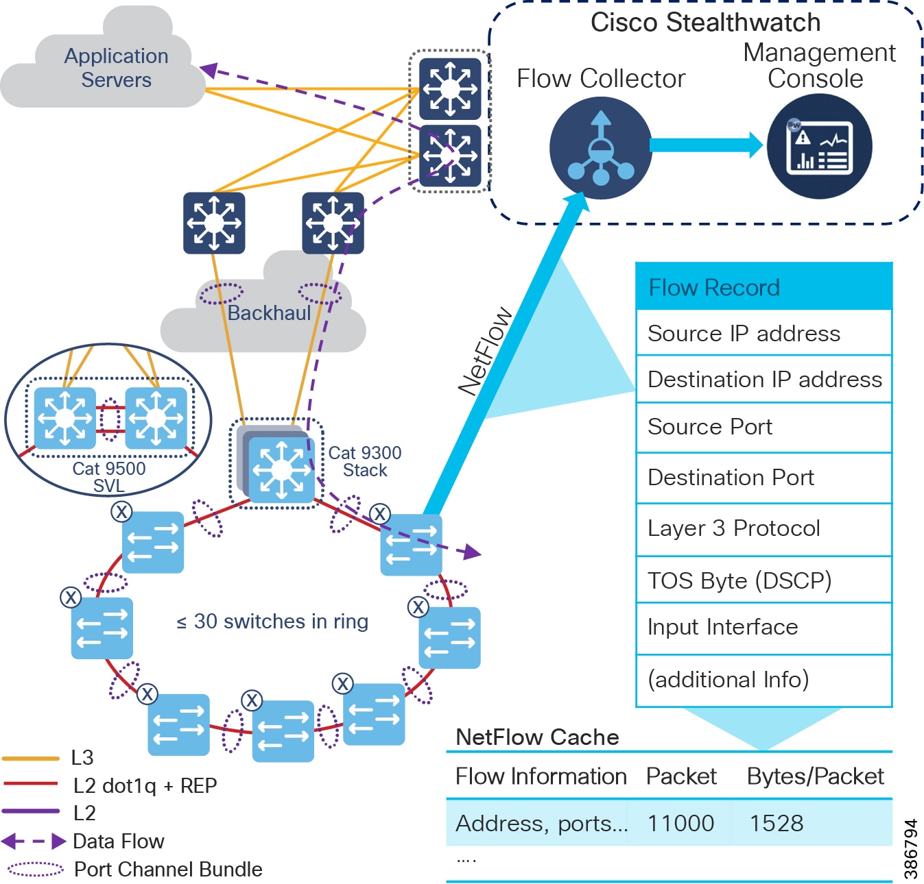
As network traffic traverses the Cisco device, flows are continuously created and tracked. As the flows expire, they are exported from the NetFlow cache to the Secure Network Analytics Flow Collector. A flow is ready for export when it is inactive for a certain time (for example, no new packets are received for the flow) or if the flow is long lived (active) and lasts greater than the active timer (for example, long FTP download and the standard TCP/IP connections). There are timers to determine whether a flow is inactive, or a flow is long lived.
After the flow times out the NetFlow record information is sent to the flow collector and deleted on the switch. Because the NetFlow implementation is done mainly to detect security-based incidents and traffic analysis, the recommended timeout for the Cisco IE 4000, Cisco IE 4010, Cisco IE 5000, and Cisco Catalyst 9300 switches is 60 seconds for the active timeout and 30 seconds for the inactive timeout. For the Cisco IE 3400, IE 3300, and ESS 3300 switches, the active is 1800 seconds, the inactive is 60 seconds, and the export timeout is 30 seconds.
In CCI, it is recommended to enable NetFlow monitoring for security on all the interfaces in the network i.e., within the PoP, between PoPs, interfaces to Data Center where application servers reside, interfaces to Fusion Router, Internet edge etc., The Configuration of NetFlow on CCI fabric devices is done through Cisco DNA Center and non-fabric devices (Eg., IE ring, FR, HER etc., can be done using Cisco DNA Center templates, which is discussed in more detail in the implementation guide.
Cisco Secure Network Analytics for CCI Security
As shown in Cisco SMC Network Security Dashboard, the main components of the Cisco Secure Network Analytics system are:
Note: The respective systems reside on different virtual or hardware appliances.
The Secure Network Analytics Flow Collector (SFC) collects the NetFlow data from the networking devices, analyses the data gathered, creates a profile of normal network activity, and generates an alert for any behavior that falls outside of the normal profile. Based on volume of traffic, there could be one or multiple Flow Collectors in a network. The Secure Network Analytics Management Console (SMC) provides a single interface for the IT security architect to get a contextual view of the entire network traffic.
The SMC has a Java-based thick client and a web interface for viewing data and configurations. The SMC enables the following:
- Centralized management, configuration, and reporting for up to 25 Flow Collectors
- Graphical Charts for visualizing traffic
- Cisco Secure Network Analytics in CCI collects NetFlow information to gain visibility across all network conversations (North-South, East-West traffic) in order to detect internal and external threats
- Conducts security analytics to obtain context to detect anomalous behaviors
- Accelerates threat detection and incident response to reduce security risk
- Integrates with ISE, has visibility of device and user information
Cisco SMC Network Security Dashboard shows Cisco Secure Network Analytics Management Console (SMC) Network Security dashboard to list the security insights like top alarming hosts, today’s alarms, flow collection trend and top applications in the network etc.,
Figure 63 Cisco SMC Network Security Dashboard
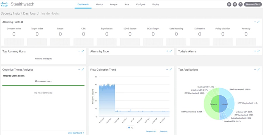
Refer to the following URL for more information on Cisco Secure Network Analytics:
- https://www.cisco.com/c/dam/en/us/td/docs/solutions/CVD/Feb2017/CVD-NaaS-Secure Network Analytics-SLN-Threat-Visibility-Defense-Dep-Feb17.pdf?dtid=osscdc000283
Because the Flow Collector and SMC are to be accessed by all endpoints in the CCI fabric network overlay, it is recommended to deploy the Flow Collector and SMC as common infrastructure devices in the CCI shared services network.
Cisco Secure Network Analytics Deployment Considerations
Some important considerations when deploying a Secure Network Analytics system include:
- Secure Network Analytics is available as both hardware (physical appliances) and virtual appliances.
- The resources allocation for the Secure Network Analytics Flow Collector are dependent on the number of Flows Per Second (FPS) expected on the network and the number of exporters (networking devices that are enabled with NetFlow) and the number of hosts attached to each networking device.
- The data storage requirements must be taken into consideration, which are again dependent on the number of flows in the network.
- A specific set of ports needs to be open for the Secure Network Analytics solution in both the inbound and outbound directions.
Refer to the following URL for installation of Secure Network Analytics, SFC scalability requirements, data storage and network inbound and outbound ports requirements:
https://www.cisco.com/c/dam/en/us/td/docs/security/stealthwatch/system_installation_configuration/SW_7_3_2_System_Configuration_Guide_DV_1_0.pdf
Security using Cisco Secure Network Analytics for abnormal traffic detection
This use case describes how a CCI network security architect can use Cisco Secure Network Analytics along with NetFlow enabled on Cisco Industrial Ethernet (IE) switches (IE 4000, IE 5000, IE 3400, IE 3300) in the ring and Cisco Catalyst 9300/9500 switches acting as distribution switches to monitor the network flows in CCI. This use case also shows the integration between Cisco ISE and Cisco Secure Network Analytics, which helps a CCI network security architect to understand the context of traffic flows occurring in the network.
By integrating Secure Network Analytics and ISE, you can see a myriad of details about network traffic, users, and devices. Instead of just a device IP address, Cisco ISE delivers other key details, including username, device type, location, the services being used, and when and how the device accessed the network.
NetFlow is enabled on all CCI networking devices to capture the traffic flows that are sent to the Flow Collector, as shown in CCI NetFlow Data Collection. Flow records from the networking devices in CCI is exported to flow collectors in an underlay network VLAN (i.e., Shared Services VLAN). The Cisco Secure Network Analytics Management Console (SMC) retrieves the flow data from the Flow Collector and runs pre-built algorithms to display the network flows. It also detects and warns if there is any malicious or abnormal behavior occurring in the network.
Figure 64 Gaining Visibility in CCI Network
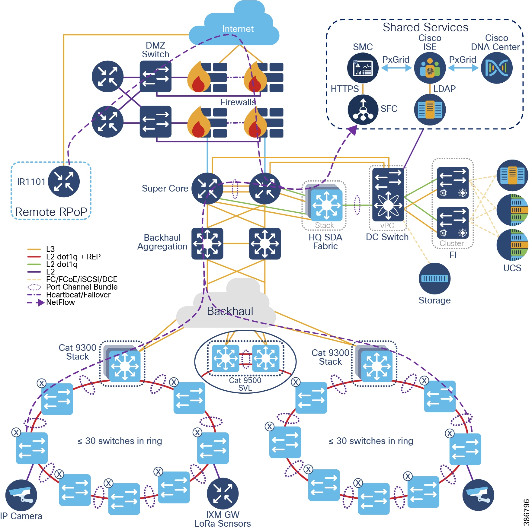
Abnormal/malicious traffic detection in CCI using Cisco Secure Network Analytics
Secure Network Analytics has many inbuilt machine learning algorithms that can assist a network security professional in detecting abnormal/malicious traffic in the network. It can detect abnormal behavior and provide the IP address of the device that is causing the propagation. This information greatly simplifies the detection process.
- Secure Network Analytics detects a possible infiltration or abnormal traffic activity using NetFlow in the CCI network by raising an alarm under High Concern index
- SMC reports an alarm indicating that there is an abnormal/malicious activity in the network.
- CCI network security professional responds to the alarm by planning the remediation that involves further investigation and restricting access to the device causing the abnormal/malicious activity in the network
- The device/user causing abnormal/malicious activity in the network is identified with the help of Cisco ISE and the network security professional triggers policy action to quarantine the device access in the network
Secure Connectivity
- LoRaWAN sensors and Network Server mutually authenticate in the Join procedure
- LoRaWAN MAC messages are signed and encrypted
- LoRaWAN payload information is encrypted
- CR-Mesh Street Light Controllers (SLCs) are 802.1X authenticated endpoints
- CR-Mesh perform 802.11i link layer encryption
- CR-Mesh is an end-to-end encrypted access network
- Control traffic between network elements is also encrypted
- Security features at access switches:
- 802.1X is an IEEE standard for media-level (Layer 2) access control, offering the capability to permit or deny network connectivity based on the identity of the end user or device. 802.1X enables port-based access control using authentication. An 802.1X-enabled switch port can be dynamically enabled or disabled based on the identity of the user or device that connects to it. Refer to the following URL for more details on 802.1X:
- https://www.cisco.com/c/en/us/td/docs/solutions/Enterprise/Security/TrustSec_1-99/Dot1X_Deployment/Dot1x_Dep_Guide.html
- MAC Authentication Bypass (MAB): MAB enables port-based access control using the MAC address of the endpoint. A MAB-enabled port can be dynamically enabled or disabled based on the MAC address of the device that connects to it. In a network that includes both devices that support and devices that do not support IEEE 802.1X, MAB can be deployed as a fallback, or complementary, mechanism to IEEE 802.1X. In CCI, endpoints that do not support IEEE 802.1X, MAB can be deployed as a standalone authentication mechanism.
- Refer to the URL: https://www.cisco.com/c/en/us/products/collateral/ios-nx-os-software/identity-based-networking-services/config_guide_c17-663759.html, for more details on MAB.
- It is recommended to enable 802.1X and MAB as fallback for 802.1X in each access port in CCI access network(s), for endpoints “host-onboarding”, authentication and authorization using Cisco ISE.
- Rate limit and QoS policy to limit bandwidth for devices and/or types of traffic
- Prevents a malicious user taking up the bandwidth and starve critical application traffic, a Denial of Service (DoS) attack
–![]() Port security with static MAC:
Port security with static MAC:
- Limits the number of MAC addresses that are able to connect to a switch and ensures only approved MAC addresses are able to access the switch
- Packets with unknown source MAC address are dropped
- Trusted endpoint devices:
- Umbrella: Umbrella is a service to set up endpoint devices to use the public Umbrella DNS servers where a set of policies is defined what endpoint devices are allowed to access or not
- AMP for Endpoints: Cisco AMP for Endpoints prevents threats at point of entry and continuously tracks every file it lets onto the endpoint devices
- Duo Beyond: Duo uses two-factor authentication secure single sign-on to provide end-users consistent user experience to access any cloud or on-premises application without go through a VPN
- Certificates: ECC-based certificate for mutual authentication with network within which the device operates
- Manufacture Usage Description (MUD) URI: Embedded MUD URI to download from MUD URI server for defining device default behavior. MUD information can be used with ISE to enforce policy.
- MUD is fully described in RFC 8520.
Cisco Cyber Vision Operational Technology (OT) Flow and Device Visibility Design
Cisco Cyber Vision gives Operational Technology (OT) teams and network managers full visibility into their assets and application flows. With this visibility, teams can implement security best practices, drive network segmentation projects, and improve operational resilience. Cisco Cyber Vision and Cisco Identity Services Engine (ISE) comprise Cisco Threat Response to help address many of the design requirements for visibility, anomaly detection, and mitigation.
Figure 65 Cisco Cyber Vision Two Tier Architecture
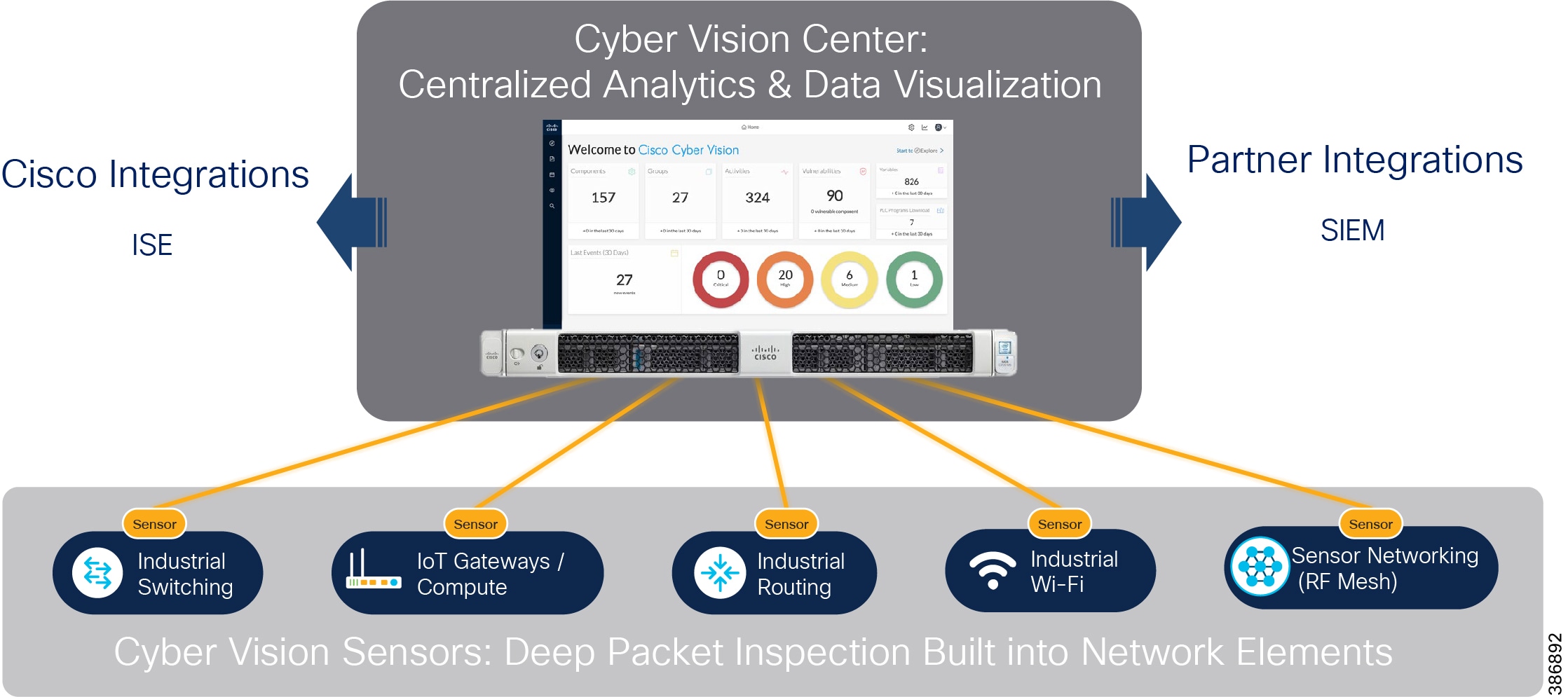
The Cisco Cyber Vision solution is a 2-tier architecture made of the inline network sensors Cisco IE3400 IE3300-X, Catalyst 9300, IR1101, and the Cisco IC3000 Industrial Compute Gateway as a dedicated hardware sensor. The sensors are dedicated to capturing network traffic using various SPAN features. The sensors then decode the SCADA protocols listed in the following table along with other supported IT protocols using the Cisco Deep Packet Inspection (DPI) engine. This meaningful information is sent to the Cisco Cyber Vision Center for passive monitoring. Visibility of legacy protocols is restricted to the Cisco IR1101.
|
|
|
|---|---|
|
|
|
|
|
Refer to the following link for more details on Cyber Vision 4.0 protocol support:
https://www.cisco.com/c/en/us/products/collateral/security/cyber-vision/cyber-vision-protocol-support.html
Cisco Cyber Vision also shows the type of devices or components that are part of the network and the flows they generate. For example, the flow of control commands, poll, and so on could be between a SCADA front end processor and its client. The device might be a SCADA station type or PC as appropriate, and the properties of the device are IP Address, Operating System, Manufacturer, and so on. These details can be derived from the flows or communication generated by the devices in the network. Gaining visibility using Cisco Cyber Vision Solution below highlights some of the details that can be deduced with the use of Cisco Cyber Vision. The Cisco Cyber Vision Center is a central platform that gathers data from all the Edge Sensors across the network and acts as the monitoring, detection, and management platform for the solution.
Figure 66 Gaining visibility using Cisco Cyber Vision Solution
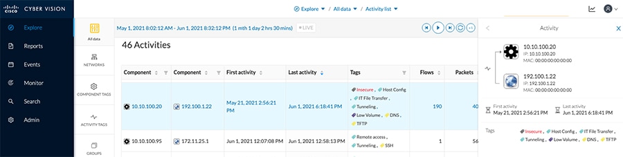
The Cisco Cyber Vision Center can be installed in any of the following ways.
- As an appliance.
- As a Virtual Machine on VMWare vSphere 6.x or later.
- As a Virtual Machine on Microsoft Hyper-V Server 2016 or later.
This guide focuses on the installation of the Cisco Cyber Vision Center as a Virtual Machine on VMWare vSphere hosted on Cisco unified computing system (UCS) platforms. Operation of the Cisco Cyber Vision Center relies on two separate networks connected to the following interfaces:
- The Administration network interface, connected to Cisco Cyber Vision user interface.
- The Collection network interface, which connects the Cisco Cyber Vision Center to the sensors.
Cisco Cyber Vision Center supports various sensors based on the deployment requirement. This guide lists various sensors along with the considerations for IT and OT traffic flow and device detection in CCI.
The different sensors are listed in the following table. Requirements dictate the choice of sensor.
Table 18 Cisco Cyber Vision Sensors for CCI Network
IT Traffic Flow and Device Detection using Cyber Vision
For a CCI configuration, a CCTV camera can be used in a traffic Safety and Security network and can be considered IT flow in the network. Cyber Vision deployment for IT flow & device detection shows devices CCTV Camera (Axis IP Camera), Sensor, Video Server, and Cisco Cyber Vision Center involved in the network for CCTV camera traffic flow and device detection. The Cyber Vision Sensor deployed on the IE3400 switch where the camera is connected, is configured as a remote switched port analyzer (RSPAN) source to switched port analyzer (SPAN) for the traffic from camera to video server to application servers at CCI headquarters (HQ) site. The captured traffic is sent to the Cyber Vision sensor for further processing and the sensor sends only metadata of the detected flow and device details via collection network to the Cyber Vision Center (CVC), as shown in Cyber Vision deployment for IT flow & device detection.
Figure 67 Cyber Vision deployment for IT flow & device detection
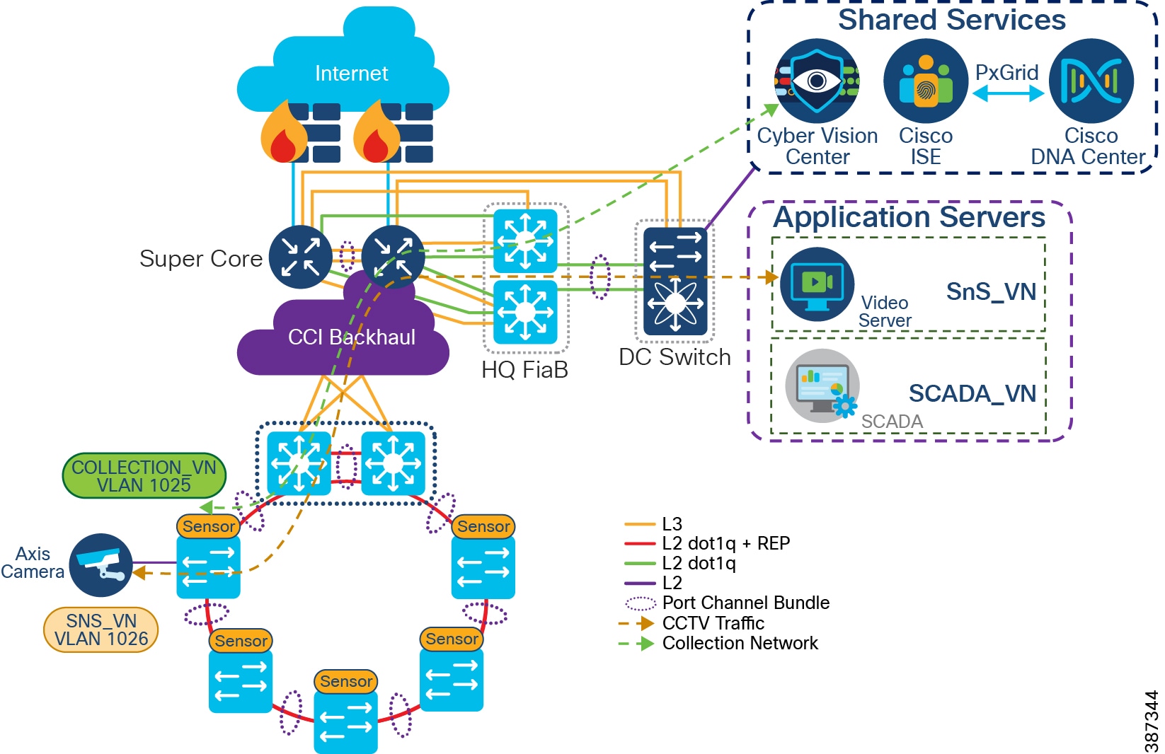
OT Traffic Flow and Device Detection using Cyber Vision
For a CCI configuration, a Water SCADA use case with DNP3 or MODBUS protocol traffic in SCADA VN network is considered an example OT flow in the network. Cyber Vision sensor deployment for OT Flow and Device Detection shows different actors like SCADA Client, Cyber Vision Sensor, SCADA Server, and Cyper Vision Center involved in the network for an OT traffic flow and device detection. Cyber Vision Sensor is deployed on the IE3400/IE3300-X switch or RPoP IR1101 gateway where endpoint is connected. It is configured as a RSPAN source to SPAN the traffic from camera to SCADA server in application servers at CCI HQ site. The captured traffic is sent to the Cyber Vision sensor for further processing and the sensor sends only metadata of the detected flow and device details via collection network to the Cyber Vision Center (CVC), as shown in Cyber Vision sensor deployment for OT Flow and Device Detection.
Figure 68 Cyber Vision sensor deployment for OT Flow and Device Detection
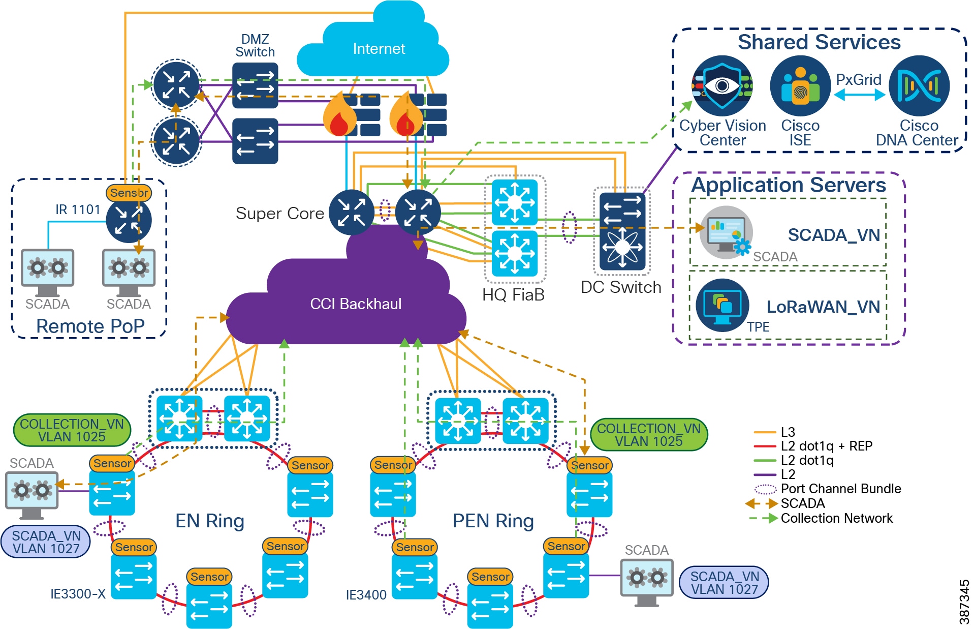
When using Cyber Vision for roadside devices, the devices communicate using the National Transportation Communications for Intelligent Transportation System Protocol (NTCIP) standard which employs SNMP protocol. The currently supported NTCIP standards are for Traffic Signal Controllers (NTCIP 1202), Dynamic Message Signs (NTCIP 1203), and Environmental Sensor Stations (NTCIP 1204) which are part of a Road Weather Information System. Using a common protocol allows different vendors to communicate with a centralized management system rather than relying on proprietary applications. The captured metadata traffic sent to the Cyber Vision Center shows this communication between roadside devices and the management system.
Design Considerations
- In CCI, the Cyber Vision Center (CVC) is deployed at Shared Services.
- CV Sensor requires two network interfaces. One interface is used to communicate with CVC to send meta-data. This interface is called the collection network interface. The other interface is for a SPAN session to capture the data traffic for processing. This is called the data acquisition network interface.
- Configuring a separate VN in CCI PoP along with subnets to assign IP addresses to CV sensors for “collection network” on Cisco IE3400 and IE3300-X switches is recommended. It eases the sensors deployment and management at the CVC.
- The data acquisition network interface on each sensor is configured as a remote VLAN 2508 as shown in IE3400/IE3300-X IOx Application Interface Mapping.
- The source interface of a SPAN session is assigned to a respective service VLAN in a VN. For example, the SCADA client connected to an IE switch is assigned with VLAN in SCADA_VN, as shown in Cyber Vision sensor deployment for OT Flow and Device Detection.
- A SPAN monitoring session on trunk interfaces of the IE switches running CV sensor will send duplicate traffic flows to the sensor application. Monitoring a range of access ports in each IE switch running CV sensor in the network is recommended.
- In CCI an EN ring of IE3300-X switches, PEN ring of IE3400 switches running CV Sensor, and RPoP IR1101 gateway running CV sensor are supported for OT device visibility as shown in Cyber Vision sensor deployment for OT Flow and Device Detection.
- Deployment of CV sensors on a C9300 and C9500 stack of switches running as a FiaB PoPs are not supported in CCI.
- OT protocols SCADA DNP3, MODBUS, and NTCIP are supported by CVC in a CCI network for flow detection. Refer to
- SCADA Protocols supported by Cisco Cyber Vision for CCI for more details about protocols supported by the Cyber Vision application for CCI.
Cisco IE3400 and IE3300-X Network Sensor
The Cisco Cyber Vision Sensor application can be hosted on the IE3400, IE3300-8U2X, or IE3300-8T2X (IE3300-X) switches. The IOx architecture of these switches provides an internal AppGigabitEthernet1/1 interface which can be configured in various modes. The configuration can be either access or trunk as required and enables connectivity for the hosted application.
Currently, an IOx application interface must have VLAN ID configured even if the AppGigabitEthernet1/1 interface is configured in access mode. Configuring the AppGigabitEthernet1/1 as a trunk interface for hosting the Cisco Cyber Vision Sensor application is recommended. The sensor application uses two interfaces, one for capturing traffic from the IE3400/IE3300-X switch physical interfaces and one for the Cisco Cyber Vision Center collection network.
The Cisco IE3400 or IE3300-X Switch can be used as a Cisco Cyber Vision Network Sensor in CCI PoPs. The IE3400 or IE3300-X may have multiple VLANs provisioned as part of a CCI SD-Access fabric segmentation. Different VLANs can also be provisioned to forward the traffic monitored on physical interfaces or VLANs of IE3400/IE3300-X, forward the same traffic to the hosted Sensor application for further processing, or enable connectivity from the sensor to the Cisco Cyber Vision Center collection network interface.
The AppGigabitEthernet1/1 interface is a non-routed interface and the sensor application interprets source packets to be GRE encapsulated. For monitoring and forwarding packets in ERSPAN format to the sensor application enable ERSPAN on the provisioned AppGigabitEthernet1/1 VLAN. IE3400/IE3300-X IOx Application Interface Mapping depicts the logical mapping of physical interfaces and the hosted IOx application on the IE3400/IE3300-X.
Figure 69 IE3400/IE3300-X IOx Application Interface Mapping
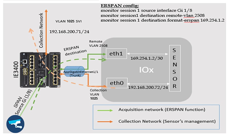
RPoP IR1101 as a Network Sensor
The Cisco Cyber Vision Sensor application can be hosted on a Cisco IR1101 router. The sensor application hosted on IR1101 requires two interfaces: one to connect the sensor to the collection network interface of the Cyber Vision Center and one to monitor the traffic on local IOS interfaces. The Cisco IR1101 IOx uses VirtualPortGroup as means to communicate between IOS and IOx application. A logical mapping of VirtualPortGroup and IOx application in a CCI RPoP is shown in RPoP IR1101 Gateway as Cyber Vision Sensor.
Similarly, the application uses a separate interface to send the processed traffic to the collection network interface. Enabling network address translation (NAT) on the VirtualPortGroup and overload using the IR1101 WAN facing interface facilitates reachability of the collection network interface of the Center for the sensor, and is recommended. The Cisco IR1101 supports serial interfaces that can be used to enable the connection of various legacy devices with serial only connectivity options.
The Cisco Cyber Vision Sensor application on CCI RPoP IR1101 used as a network sensor can enable visibility to some serial data. Smart Water SCADA devices that have support for DNP3 or MODBUS protocols can be connected to CCI network using the Cisco IR1101 as a gateway. The Cisco IR1101 supports SCADA protocol translation capability that can be used to translate DNP3 Serial to DNP3 IP. The Cisco IR1101 also supports a method to transfer serial data through an IP Network using Raw Socket. This guide proposes to use the IR1101 egress IP interface as an encapsulated remote switched port analyzer (ERSPAN) source to capture serial data. The egress interface can also be a Flex VPN IPsec tunnel that carries the traffic of interest.
Figure 70 RPoP IR1101 Gateway as Cyber Vision Sensor
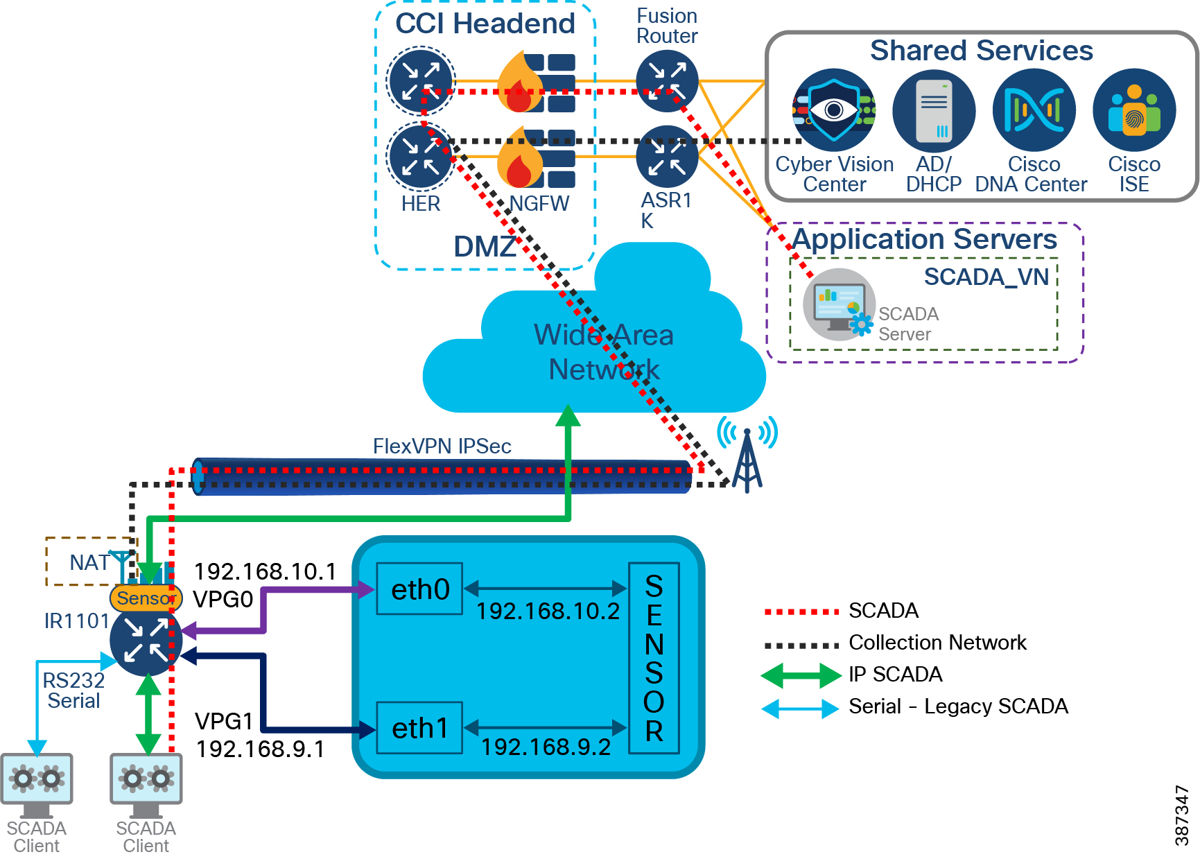
Cyber Vision uses the following two methods to determine the correct maximum transmission unit (MTU) in the network.
- The RPoP IR110 running CV Sensor can either set the maximum segment size (MSS) value in the TCP synch packets to the correct value, or
- It can send ICMP fragmentation needed packets back to the CV Center or sensor.
- If neither of the above occur, the Cyber Vision cannot know the correct MTU in the network. Hence, it is the responsibility of the people configuring the devices in the network path to allow one of the two mechanism to work (either sending and allowing ICMP back to the center and sensor, or setting the "tcp-adjust-mss" on the interface with the lowest MTU) or manually adjust the MTU.
Note: Manually configuring the RPoP tunnel interface with the MTU value is recommended. This method is suggested by the service provider of the WAN/LTE backhaul. Also configure the "tcp-adjust-mss" value as calculated using the following formula for successful operation of Sensors in a RPoP with CVC in a CCI site.
MSS Value = MTU of Physical Cellular Inf - 20 (TCP Header) - 20 (IP Header) - 4 (GRE Header) - 73 (Max IPSec Overhead bytes).
Network QoS Design
Quality of Service refers to the ability of a network to provide preferential or differential services to selected network traffic. QoS is required to ensure efficient use of network resources while still adhering to the business objectives. This chapter covers CCI QoS design considerations and recommendations for various CCI network traffic classes and it includes the following topics:
CCI Wired Network QoS design
QoS refers to network control mechanisms that can provide various priorities to different CCI endpoints or traffic flows or to guarantee a certain level of performance of a traffic flow in accordance with requests from the application program. By providing dedicated bandwidth, controlled jitter and latency (required by some real-time and interactive traffic), and improved loss characteristics, QoS can ensure better service for selected network traffic.
The CCI network architecture consists of different kinds of switches and routers with different feature sets. In order to streamline traffic flow, differentiate network services and reduce packet loss, jitter and latency, a well-designed QoS model is very important to guarantee network performance and operation. This section discusses the CCI QoS design considerations taken into account for various traffic classes in the CCI wired network architecture.
It includes QoS design considerations on fabric devices of CCI i.e Cisco Catalyst 9300 Switches stack and 9500 switches StackWise Virtual (SVL) and Ethernet access rings consisting of Cisco Industrial Ethernet (IE) switches.
QoS Design for Fabric Devices
You can configure QoS in CCI fabric devices in CCI PoPs, transit site and HQ/DC site Fabric-in-a-Box (FiaB) switches using Cisco DNA Center. These fabric devices are Cisco Catalyst 9300 Series Switches stack and Cisco Catalyst 9500 Switches SVL and Cisco DNA Center uses application policies to configure QoS on these devices in the network.
Note: QoS application classes and queuing profile design recommendations discussed in this section are based on application traffic-classes and output queuing profile templates available in Cisco DNA Center application policy feature, as shown in Cisco DNA Center Application Queuing Profile Template. The queuing profile configuration in Cisco DNA Center requires a minimum of at least 1% bandwidth allocation for each of the application traffic-class.
Figure 71 Cisco DNA Center Application Queuing Profile Template
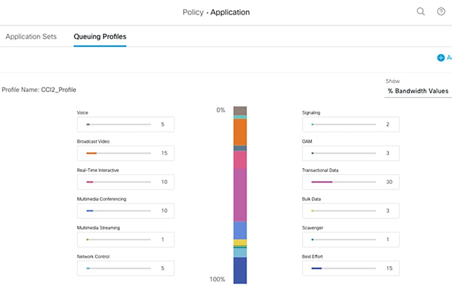
Refer to the following URL, for more details on Cisco DNA Center QoS policies:
Cisco DNA Center Application policies comprise these basic parameters:
- Application Sets—Sets of applications with similar network traffic needs. Each application set is assigned a business relevance group (business relevant, default, or business irrelevant). For applications in the Relevant Business category, Cisco DNA Center assigns traffic classes to applications based on the type of application. It is recommended that QoS parameters in each of the three groups are defined based on this Cisco Validated Design (CVD). You can also modify some of these parameters to more closely align with your objectives.
- Site Scope—Sites to which an application policy is applied. If you configure a wired policy, the policy is applied to all the wired devices in the site scope. Likewise, if you configure a wireless policy for a selected service set identifier (SSID), the policy is applied to all of the wireless devices with the SSID defined in the scope.
Cisco DNA Center takes all of these parameters and translates them into the proper device CLI commands. When you deploy the policy, Cisco DNA Center configures these commands on the devices defined in the site scope.
Cisco DNA Center Application Policy constructs and their organization are depicted in Cisco DNA Center Application Queuing Profile Template below:
Figure 72 Cisco DNA Center Application Policy Constructs
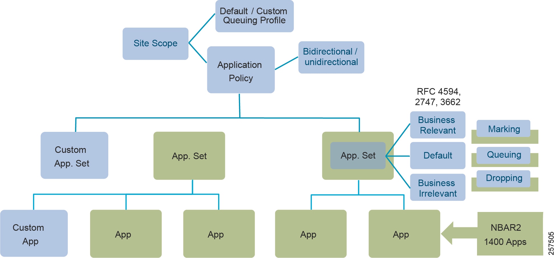
- Applications and Application Sets: Applications are the software programs or network signaling protocols. Cisco DNA Center recognizes over 1400 distinct applications listed in the Cisco Next Generation Network-Based Application Recognition (NBAR2) library, including over 150 encrypted applications. Each application is mapped into similar industry standards-based traffic classes, as defined in RFC 4594. The traffic classification defines a Differentiated Services Code Point (DSCP) marking, queuing, and dropping policy to be applied based on the business relevance group to which it is assigned.
- Custom applications can be defined for wired devices that are not included in NBAR2. Custom applications can be defined based on server name, IP address and port, or URL. DSCP and port can also be specified for custom applications.
Note: Given the specialist nature of many of the typical applications and use cases supported by CCI, there is a significant likelihood that there will be important or business critical applications that are not part of NBAR2 and hence it is recommended that special attention be paid to the potential need to define Custom Applications for Policy purposes.
- Queuing Profile: Queuing profiles define an interface's bandwidth allocation based on the interface speed and the traffic class.
- Business-Relevance: Three classes of business-relevance groups are defined:
–![]() Business Relevant: Maps to industry best-practice preferred-treatment recommendations prescribed in IETF RFC 4594.
Business Relevant: Maps to industry best-practice preferred-treatment recommendations prescribed in IETF RFC 4594.
–![]() Default: Maps to a neutral-treatment recommendation prescribed in IETF RFC 2474 as “Default Forwarding.”
Default: Maps to a neutral-treatment recommendation prescribed in IETF RFC 2474 as “Default Forwarding.”
–![]() Business Irrelevant: Maps to a deferred-treatment recommendation prescribed in IETF RFC 3662
Business Irrelevant: Maps to a deferred-treatment recommendation prescribed in IETF RFC 3662
Note: RFC 4594 QoS provides guidelines for marking, queuing, and dropping principles for different types of traffic. Cisco has made a minor modification to its adoption of RFC 4594, namely the switching of Call-Signaling and Broadcast Video markings (to CS3 and CS5, respectively).
- Unidirectional and Bidirectional Application Traffic: By default, the Cisco DNA Center configures all applications on switches and wireless controllers as unidirectional, and on routers as bidirectional. However, any application within a particular policy can be updated as unidirectional or bidirectional.
- Consumers and Producers: A traffic relationship between applications (a-to-b traffic flow) can be defined that needs to be handled in a specific way. The applications in this relationship are called producers and consumers. Setting up this relationship allows you to configure specific service levels for traffic matching this scenario.
- Cisco DNA Center configures QoS policies on devices based on the QoS feature set available on the device. For more information about QoS implementation, refer to the Cisco DNA Center User Guide at the following URL:
https://www.cisco.com/c/en/us/td/docs/cloud-systems-management/network-automation-and-management/dna-center/2-2-3/user_guide/b_cisco_dna_center_ug_2_2_3/b_cisco_dna_center_ug_2_2_3_chapter_01100.html#id_51875
Note: QoS configuration using Cisco DNA Center application policy is currently not supported (as of SD Access release 2.2.3.3) on Extended Nodes (Cisco Industrial Ethernet 4000, IE 5000, IE 3300 1G and ESS 3300 series switches) in the ring. This Cisco DNA Center bases its marking, queuing, and dropping treatments on IETF RFC 4594 and the business relevance category that you have assigned to the application.
QoS Classification, Marking and Queuing Policy
Cisco DNA Center bases its marking, queuing, and dropping treatments based on the Cisco implementation of RFC 4594 and the business relevance category that you have assigned to the application. Cisco DNA Center assigns all of the applications in the Default category to the Default Forwarding application class and all of the applications in the Irrelevant Business category to the Scavenger application class. For applications in the Relevant Business category, Cisco DNA Center assigns traffic classes to applications based on the type of application.
Application Policy feature in Cisco DNA Center provides a non-exhaustive list of all applications or traffic classes in a network, as shown in Cisco DNA Center QoS Application Classification and Queuing Policy below. It also shows CCI network applications or traffic classes that are mapped to the applications classes in Cisco DNA Center for deploying QoS ingress classification, marking and egress queuing policies in fabric devices.
Note: As per RFC 4594, the Broadcast Video service class is recommended for applications that require near-real-time packet forwarding with very low packet loss of constant rate and variable rate inelastic traffic sources that are not as delay sensitive as applications using the Real-Time Interactive service class. Such applications include broadcast TV, streaming of live audio and video events, some video-on-demand applications, and video surveillance.
Queuing Profile Bandwidth Allocation and Policing
The policing function limits the amount of bandwidth available to a specific traffic flow or prevents a traffic type from using excessive bandwidth and system resources. A policer identifies a packet as in or out of profile by comparing the rate of the inbound traffic to the configuration profile of the policer and traffic class. Packets that exceed the permitted average rate or burst rate are out of profile or nonconforming. These packets are dropped or modified (marked for further processing), depending on the policer configuration.
The following policing forms or policers are supported for QoS:
Application Policy makes use of a queuing profile with bandwidth allocation for each class of traffic defined in Cisco DNA Center QoS Application Classification and Queuing Policy and configures QoS commands on devices as per the queuing profile defined. Cisco DNA Center QoS application policy configures single rate two-color policing on the egress interfaces. Based on different classes of traffic in CCI (as shown in Cisco DNA Center QoS Application Classification and Queuing Policy), it is recommended to allocate bandwidth in queuing profile for each of these traffic classes as shown in CCI QoS Traffic Profile.
Table 20 CCI QoS Traffic Profile
CCI QoS Considerations
- Each port in Cisco Catalyst 9300 and 9500 Series switches in supports eight egress queues, of which two can be given a priority (i.e.2P6Q3T Queuing model). Table 3 shows an egress queuing and policing policy for different classes of traffic in CCI network.
- It is recommended to classify CCI network traffic as shown in Cisco DNA Center QoS Application Classification and Queuing Policy. Classification and Marking should be applied to all traffic types at its entry point into the network, on the ingress port, for the entire network hierarchy, regardless of available bandwidth and expected traffic.
- Classify IoT use case traffic into Transactional data class and provide QoS treatment both in terms of bandwidth and priority. If distinction is possible, IoT control traffic needs to get priority similar to network control traffic and IoT management traffic similar to network management/telemetry data. If distinction is not possible, classify all IoT traffic similar to transactional data traffic. However, it is preferable to not mix IoT traffic with network control traffic, but instead keep a separate queue for IoT traffic.
- Limit total priority queuing traffic (LLQ) to 33% of link capacity, apply unconditional policing, to bound application response time of non-priority applications. No strict priority traffic recommended.
- Select only desired applications and corresponding application sets from the NBAR2 library. Most of the enterprise apps can be found in NBAR2 library.
- Custom applications may be defined when source marking is not done. This is based on destination “Server IP/Port or URL.” Producer-Consumer-based classification can be used in specific cases.
Note: NBAR2-based traffic classification and marking is configured in the ingress policy. Ingress policy is applied only to devices in access role on access port. For devices with non-access role (distribution, border, and core), only the queuing profile is applied at the egress port.
- Traffic from different IoT CCI solutions (e.g., Smart Street Lighting with CR-Mesh, LoRaWAN, DSRC for Roadways, LoRaWAN for parking, or IP Camera traffic for Safety and Security). As per the recommendation of this guide, this traffic is marked distinctly as IoT Traffic for QoS treatment. This is only a sample list for IoT traffic; the operator can refine the list to match specific deployment needs.
Note: The application policy defined by the Cisco DNA Center can be deployed to all desired sites for the selected devices and ports, except for IE switches. Thus, the application policy is applied to the uplink traffic from IE switches starting from distribution switches the Fabric Edge.
Ethernet Access Ring QoS Design
This section covers QoS design for CCI Ethernet access ring consisting of Cisco Industrial Ethernet (IE) 4000, IE 5000, IE 3300, ESS 3300, and IE 3400 Series switches in the daisy-chained ring topology configuration in CCI PoP. Cisco DNA Center does not support application policy (QoS) provisioning on these switching platforms in SD Access release 2.1.3.0. Therefore, it is recommended to configure QoS on these platforms using Cisco DNA Center Day N templates feature.
IE4000 and IE5000 Series Switches QoS Design
Classification distinguishes one kind of traffic from another by examining the fields in the packet header. When a packet is received, the switch examines the header and identifies all key packet fields. A packet can be classified based on an ACL, on the DSCP, the CoS, or the IP precedence value in the packet, or by the VLAN ID. You use a Modular QoS CLI(MQC) class map to name a specific traffic flow (or class) and to isolate it from all other traffic. A class map defines the criteria used to match against a specific traffic flow to further classify it. If you have more than one type of traffic that you want to classify, you can create another class map and use a different name.
You can use packet marking in input policy maps to set or modify the attributes for traffic belonging to a specific class. After network traffic is organized into classes, you use marking to identify certain traffic types for unique handling. For example, you can change the CoS value in a class or set IP DSCP or IP precedence values for a specific type of traffic.
These new values are then used to determine how the traffic should be treated. You can also use marking to assign traffic to a QoS group within the switch.
Traffic marking is typically performed on a specific traffic type at the ingress port. The marking action can cause the CoS, DSCP, or precedence bits to be rewritten or left unchanged, depending on the configuration. This can increase or decrease the priority of a packet in accordance with the policy used in the QoS domain so that other QoS functions can use the marking information to judge the relative and absolute importance of the packet. The marking function can use information from the policing function or directly from the classification function.
- In CCI, it is recommended to mark QoS DSCP values at the source endpoint of the traffic flow, when the source endpoints support QoS DSCP marking. Source DSCP marking is trusted at ingress port on the IE switch to which the endpoint is connected.
- It is recommended to classify and mark the packets (for all other traffic types that cannot be source marked) at its entry point into the network, on the ingress port, for the entire network hierarchy, regardless of available bandwidth and expected traffic.
- For IoT application/sensor data traffic for which if the device source marking is not possible, it is suggested to classify and mark the IoT traffic using Classification based on QoS ACL method (IP ACLs)
- Depending on the traffic class and marking (if source marking is done) at the ingress IE switch port, you can trust/re-mark the ingress Layer 3 DSCP marking and set the QoS group for egress output policy classification in the switch. A QoS group is an internal label used by the switch to identify packets as a member of a specific class. The label is not part of the packet header and is restricted to the switch that sets the label. QoS groups provide a way to tag a packet for subsequent QoS action without explicitly marking (changing) the packet.
Note: NBAR2 based classification and marking is not supported on Cisco Industrial Ethernet Switching platforms.
- It is recommended to classify and configure DSCP value of CS1 (Scavenger class) marking for the unknown hosts/endpoints in the quarantine VN. All endpoints/hosts which connect to IE ring are initially assigned with a quarantine VLAN (in quarantine VN) if initial 802.1X/MAB does not allocate to a trusted VN, or if the access port is not statically mapped to a trusted VN. The endpoints/hosts that are successfully authenticated (using 8021.X/MAB) and authorized (i.e. become trusted endpoints) for network access in a respective VN in CCI. Hence, the endpoints must do source DSCP marking once it is authorized in the network so that source marking is trusted and not changed at IE switch ingress port. For QoS policy for both the untrusted quarantined endpoints, and the trusted endpoints that can't do source marking, it is recommended to match on the IP subnets (IP ACL).
Queuing and Policing
Queuing establishes buffers to handle packets as they arrive at the switch (ingress) and leave the switch (egress). Each port on the switch has ingress and egress queues. Both the ingress and egress queues use an enhanced version of the tail-drop congestion-avoidance mechanism called weighted tail drop (WTD). WTD is implemented on queues to manage the queue lengths and to provide drop precedence for different traffic classifications. Each queue has three thresholds to proactively drop packets before queues fill up. Traffic classes assigned to thresholds 1 or 2 will be dropped if the queue buffer has reached the assigned threshold. Traffic classes assigned to a threshold of 3 for a specific queue will only be dropped if that queue has filled its buffer space.
Both Cisco Industrial Ethernet (IE) 4000 and 5000 Series switches in access ring support four egress queues, out of which one queue can be given a priority (i.e, 1P3Q3T Queuing model). Voice and CCTV Camera or other real-time interactive video traffic classes in the CCI network are prioritized with unconditional policing at 30% of interface bandwidth rate.
- Limit total priority queuing traffic (LLQ), apply unconditional policing with bandwidth percent (30% of link capacity), to bound application response time of non-priority applications. No strict priority traffic recommended.
- Class-Based Weighted Fair Queuing (CBWFQ) with Waited Tail Drop (WTD) is recommended for remaining classes of traffic in the rest of the egress queue.
QoS design for IE4000 and IE5000 Series Switches in the ring shows traffic classes (input policy) and queue mapping (output policy) design for Cisco Industrial Ethernet (IE) 4000 and 5000 Series in the access ring.
Figure 73 QoS design for IE4000 and IE5000 Series Switches in the ring
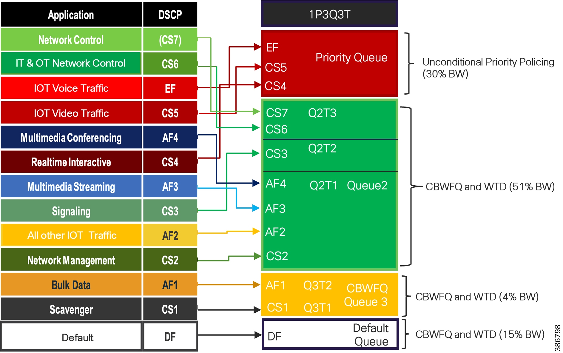
CCI QoS Configuration for Cisco IE 5000/4000 Series Switches shows QoS configuration with WTD recommendation for output queue buffer for Cisco Industrial Ethernet (IE) 4000 and IE 5000 Series switches in the access ring.
Refer to the following URL for more details on configuring QoS on Cisco Industrial Ethernet (IE) 4000 and IE 5000 series switches:
IE3300 and IE3400 Series Switches QoS Design
Cisco Industrial Ethernet (IE) 3300, ESS 3300, and IE 3400 Series switches in the Ethernet access ring support 1P7Q2T egress queuing model. The traffic classification and marking design (input policy) for these switches in the access ring are same as QoS for Fabric devices, discussed in the section “QoS Design for Fabric Devices” as Cisco DNA Center release 2.2.3 support Application QoS for IE3300 10G and IE3400 Series switches.
Note: Cisco Industrial Ethernet (IE) 3300, ESS 3300, and IE 3400 Series switches support ingress policing. However, ingress policing along with NetFlow are mutually exclusive and it is not supported together on a switch port. Hence, it is recommended to configure only ingress classification and marking based QoS input policy, for these switches in the ring.
Class-Based Weighted Fair Queuing
Cisco Industrial Ethernet (IE) 3300, ESS 3300, and IE 3400 Series switches support only strict priority in the egress switch port. With strict priority queuing, the priority queue is constantly serviced. All packets in the queue are scheduled and sent until the queue is empty. Priority queuing allows traffic for the associated class to be sent before packets in other queues are sent. Strict priority queuing (priority without police) assigns a traffic class to a low-latency queue to ensure that packets in this class have the lowest possible latency. When this is configured, the priority queue is continually serviced until it is empty, possibly at the expense of packets in other queues. For fair egress queuing all the traffic classes in CCI network, it is recommended to configure CBWFQ in egress policy on these switching platforms.
You can configure class-based weighted fair queuing (CBWFQ) to set the relative precedence of a queue by allocating a portion of the total bandwidth that is available for the port. You use the bandwidth configuration command to set the output bandwidth for a class of traffic as a percentage of total bandwidth.
When you use the bandwidth configuration command to configure a class of traffic as a percentage of total bandwidth, this represents the minimum bandwidth guarantee (CIR) for that traffic class. This means that the traffic class gets at least the bandwidth indicated by the command but is not limited to that bandwidth. Any excess bandwidth on the port is allocated to each class in the same ratio in which the CIR rates are configured.
QoS design for IE3300 1GE and ESS 3300 Switches in the ring shows traffic classes (input policy) and queue mapping (output policy) design for Cisco Industrial Ethernet (IE) ESS 3300 switches in the access ring.
Figure 74 QoS design for IE3300 1GE and ESS 3300 Switches in the ring
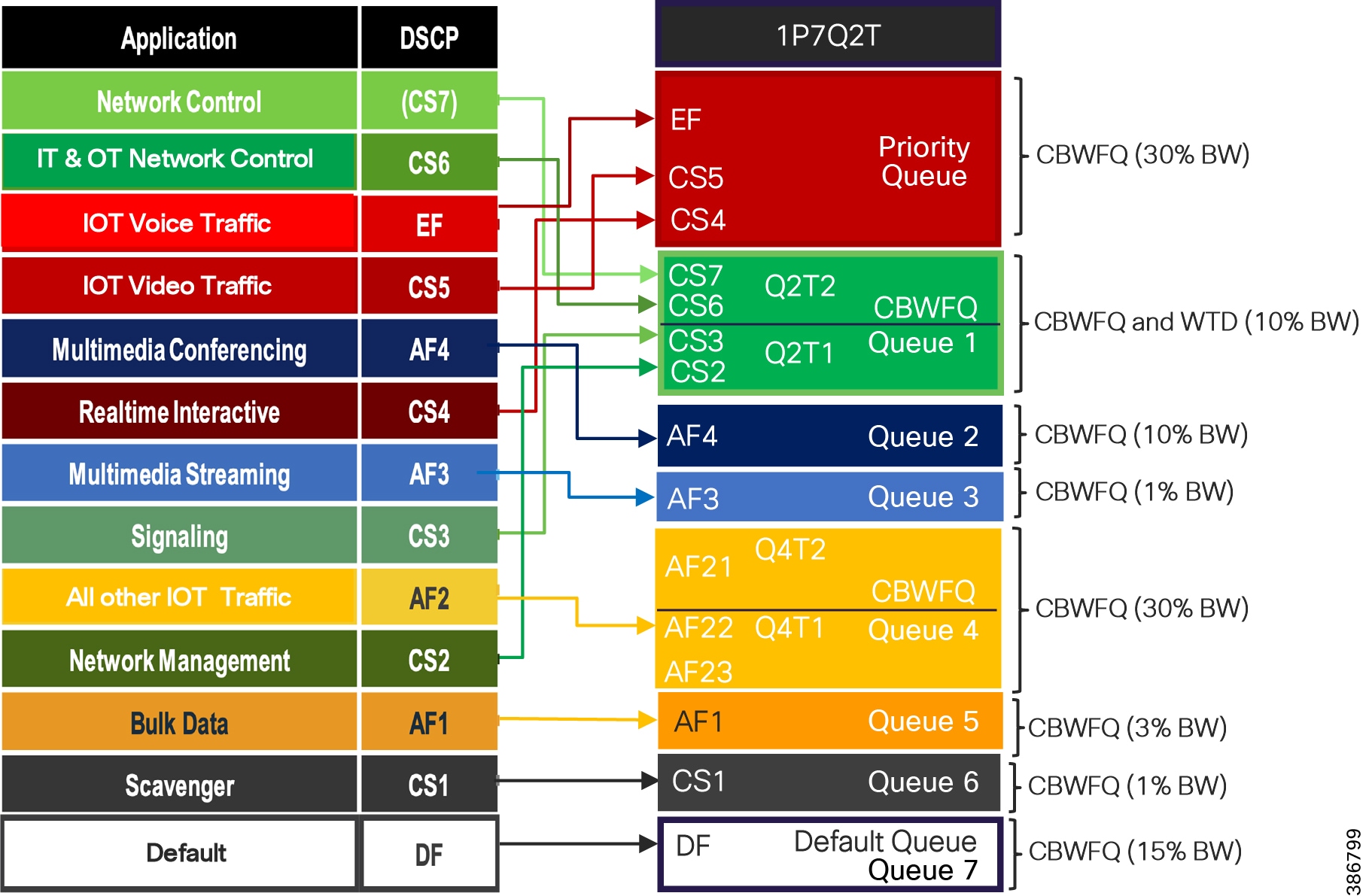
CCI QoS Configuration for Cisco IE 3x00 and ESS 3300 Series Switches shows QoS configuration with bandwidth percent recommendation for output queue for Cisco Industrial Ethernet (IE) 3300 and IE 3400 Series switches in the access ring..
IE3300 10G and IE3400 switches, as Extended and Policy Extended Nodes in the access ring, support Application QoS provisioning using Cisco DNA Center. Application QoS policy provisioning for these switches are discussed in detail in the implementation guide of this CVD. It is recommended to provision QoS configurations on these switches using Application QoS feature in Cisco DNA Center.
CCI Wireless Network QoS Design
This section covers the QoS design for Wireless LAN (WLAN) access networks in CCI. Cisco Unified Wireless & Industrial Wireless products support Wi-Fi MultiMedia (WMM), a QoS system based on IEEE 802.11e that has been published by the Wi-Fi Alliance. Cisco Unified Wireless Network (CUWN) mesh over-the-top on CCI fabric and SD-Access Wireless designs support WLAN QoS based on QoS profiles, WMM policy used by WLC in the CCI.
Wireless LAN QoS features are an implementation of the Wi-Fi Alliance WMM certification, based on the IEEE 802.11e amendment. Any wireless client that is certified WMM can implement Wireless LAN QOS in the upstream direction (from the wireless client to the AP). Any client certified 802.11n or 802.11ac is also certified WMM.
Regardless of the client support (or lack of support) for WMM, Cisco access points support WMM and can be configured to provide wireless QoS in the downstream direction (from the AP toward the wireless clients), and in the upstream direction when forwarding wireless frames to the wired interface.
For more details on WLAN QoS and WMM, refer to the Cisco Unified Wireless QoS chapter in Enterprise Mobility Design Guide at the following URL:
- https://www.cisco.com/c/en/us/td/docs/wireless/controller/8-5/Enterprise-Mobility-8-5-Design-Guide/Enterprise_Mobility_8-5_Deployment_Guide/ch5_QoS.html
Cisco Unified Wireless Mesh Access Network QoS Considerations
Following are key QoS considerations taken into account for WLAN QoS in CCI:
- WMM uses IEEE 802.1P Classification scheme which has eight user priorities (UP 0-7) that WMM maps to four access categories Voice (AC_VO), Video (AC_VI), Best Effort (AC_BE) and Background (AC_BK).
- WLC QoS profiles can be configured as “Metal Policies”:
- CAPWAP control frames require prioritization so they are marked with a DSCP classification of CS6.
- IoT WMM-enabled Wi-Fi clients have the classification of their frames mapped to a corresponding DSCP classification for CAPWAP packets to the WLC. Based on WLAN/SSID QoS profile setting, the CAPWAP outer DSCP marking is capped to a maximum DSCP value allowed for that QoS profile. Eg., In a Video profile, DSCP would be capped to 34. When a WMM-enabled Wi-Fi client has a DSCP marking of EF and associates to a SSID with Video QoS profile settings, the CAPWAP packets DSCP value would be set to 34 for upstream traffic (AP -> WLC).
- This DSCP value is translated at the WLC to a CoS value on 802.1Q frames leaving the WLC interfaces.
- It is recommended to trust DSCP upstream on the WLC. When you trust DSCP upstream at WLC, DSCP is used instead of UP. DSCP is already used to determine the CAPWAP outer header QoS marking downstream. Therefore, the logic of downstream marking is unchanged. In the upstream direction though, trusting DSCP compensates for unexpected or missing UP marking. The AP will use the incoming 802.11 frame DSCP value to decide the CAPWAP header outer marking. The QoS profile ceiling logic still applies, but the marking logic operates on the frame DSCP field instead of the UP field.
- IoT Non-WMM Wi-Fi clients have the DSCP of their CAPWAP tunnel set to match the default QoS profile for that WLAN (SSID). For example, the QoS profile for a WLAN supporting Wi-Fi Cameras would be set to Gold, resulting in a DSCP classification of 34 (AF41) for data frames packets from that AP WLAN.
- The WMM classification used for traffic from the AP to the WLAN client is based on the DSCP value of the CAPWAP packet, and not the DSCP value of the contained IP packet. Therefore, it is critical that an end-to-end QoS system be in place.
- For WLAN (SSID) traffic which are locally switched at IE switch in the access ring, FlexConnect APs mark 802.1P value (UP) in the 802.1Q VLAN tag for upstream traffic. For downstream traffic, FlexConnect APs use the incoming 802.1Q tag from the Ethernet side and then use this to queue and mark the WMM values on the radio of the locally-switched VLAN.
Wireless LAN QoS Model
The QoS for the wireless traffic at the CCI wireless (Wi-Fi) LAN is enabled through QoS policies also known as metal policies (Platinum, Gold, Silver and Bronze) at Centralized WLC or Per PoP WLC. The WLAN for each Wi-Fi Service in CCI (Ex. Wireless Cameras, Public Wi-Fi etc.,) is associated with a QoS policy. The QoS policy supports WMM UP and DSCP marking for the Wi-Fi traffic, as shown in WLAN QoS Model for CCI.
Figure 75 WLAN QoS Model for CCI
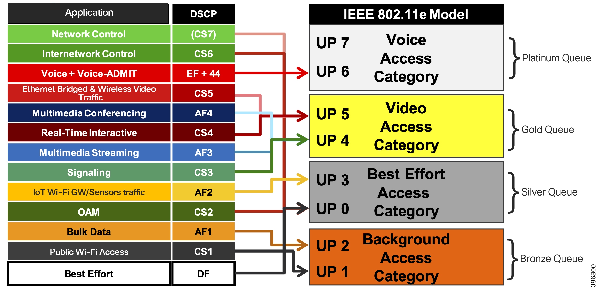
SD-Access Wireless QoS Policy Overview also represents the Wi-Fi traffic queuing and mapping in the radio backhaul interface for each MAP in a Centralized or Per-PoP WLC based CUWN Wi-Fi mesh access network in CCI.
Note: Ethernet Bridged Traffic of the endpoints connected to the Ethernet ports of MAPs are not CAPWAP encapsulated (no outer header for bridged Ethernet packets). DSCP marking of such end points is used to map the traffic to the right queue in the Wi-Fi backhaul. Hence, it is recommended to classify and mark the DSCP at source of Ethernet Bridged Traffic to ensure appropriate QoS treatment for the traffic in the radio backhaul.
- It is recommended to source mark CCTV Cameras connected to MAPs with DSCP value of CS5 to ensure appropriate QoS treatment for this traffic in CCI wired network, as discussed in the previous section. If source DSCP marking is not possible on the device, Ethernet access ring QoS should classify the device using ACLs and mark the packet with DSCP value of CS5 at the ingress port of the Ethernet switch in the ring.
- Wireless CCTV Camera traffic in a WLAN should be source marked with UP value of 5 (if UP marking is supported) with DSCP value of CS5 to ensure appropriate QoS egress queuing (AC_VI) in the radio backhaul. This ensures Wireless CCTV Cameras traffic QoS treatment as per CCI wired network QoS design.
- Any IoT Wi-Fi sensors or gateways connecting to WLAN should be configured with WMM UP value 2 (if WMM is supported) and DSCP value AF21 for Best Effort queuing in radio backhaul. Non-WMM based Wi-Fi sensors or gateways have the DSCP of their CAPWAP tunnel set to match the default QoS profile for that WLAN.
- Public Wi-Fi users or WLAN in the network is classified with UP value 1 and DSCP value CS1 for Background queuing in radio backhaul and QoS treatment in wired network.
SD-Access Wireless Network QoS Considerations
SD-Access wireless network architecture in CCI uses Fabric-enabled WLC (eWLC on C9300 Switch stack FiaB) which is part of fabric control plane and fabric enabled APs encapsulates fabric SSID or WLAN traffic in VXLAN, Hence QoS design and behavior for SD-Access Wi-Fi clients in CCI, is same as Wired QoS policy design considerations which are discussed in the section CCI Wired Network QoS design.
This section covers the SD-Access Wireless QoS design considerations between Fabric APs and WLC in CCI PoP for QoS treatment of Wi-Fi traffic. SD Access Wireless network with Fabric APs and WLC follow WLAN QoS and AVC policy model with WMM metal policies for traffic classification and remarking at WLC.
- Fabric APs acts as access edge trust boundaries to trust upstream DSCP marking of Wi-Fi traffic and Fabric WLC (eWLC) acts as WLAN/SSID policy enforcement point (PEP) for remarking upstream Wi-Fi traffic DSCP using QoS policy.
- It is recommended to remark DSCP value at WLC using AVC policy as shown in WLAN QoS Model for CCI for each class of Wi-Fi traffic to ensure appropriate QoS treatment for each class of traffic as per CCI wired network QoS design.
- Wi-Fi traffic QoS treatment at wireless or radio access medium is based on DSCP (i.e, upstream DSCP trusting enabled at WLC) and DSCP-to-UP (downstream) mapping at AP.
SD-Access Wireless QoS Policy Overview shows an overview of SD Access Wireless QoS policy operation for Fabric WLC as PEP.
Figure 76 SD-Access Wireless QoS Policy Overview
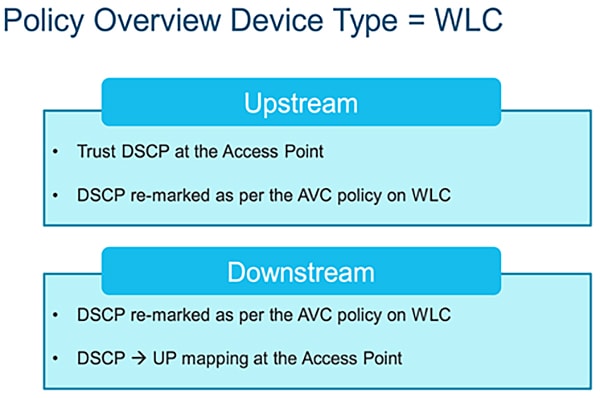
CCI QoS Treatment for CR-Mesh and LoRaWAN Use Cases Traffic
The CCI network is used by several IoT use cases. Each IoT use case can generates different types of traffic. This section discusses QoS treatment specific to CR-Mesh (Eg., Cimcon Street Lighting and LoRaWAN FlashNet Street Lighting) use cases traffic.
CCI QoS Design Considerations for CR-Mesh Traffic
The CR-Mesh use case traffic to/from the Connected Grid Endpoint (CGE) passes through the FAR. The FAR router is connected to an IE series switch in Ethernet Access ring or connects to CCI via an RPoP cellular link. All traffic from the FAR is encrypted and tunneled to the headend router (HER) located at the DMZ. Individual CR-Mesh traffic flows are hidden to all intermediate nodes.
Entire tunneled traffic originating from a FAR can be given a single QoS treatment at the IE access switch to which the FAR is connected. Classification and marking can be done based on the interface to which the FAR is connected or based on the FAR subnet (ACL based classification). The FAR subnet is the source IP subnet used for tunneling the CR-Mesh traffic. As discussed earlier, since CR-Mesh is IoT traffic, all CR-Mesh traffic passing through the tunnel is marked with IP DSCP AF21. A minimum of 30% of the uplink port bandwidth is guaranteed for all IoT traffic marked with IP DSCP AF21 in the entire path. The IP DSCP marking is done on the outer header of the encapsulated packet. This outer header marking is used for QoS policy enforcement in the rest of the network.
QoS classification and marking is applied to CR-Mesh traffic at IE series switches and queuing policy is applied thereafter from the fabric edge onwards. As per customer's needs, and where relevant, MPLS QoS mapping needs to be done at the service provider edge.
CCI QoS Design Considerations for LoRaWAN Traffic
Cisco Wireless Gateway for LoRaWAN access network aggregates all LoRaWAN Sensors traffic (Eg. FlashNet Lighting Controller) to ThingPark Enterprise (TPE) Network Server (NS) in CCI HQ/DC site. Since the LoRaWAN gateway is connected to an IE switch port in Ethernet access ring in a CCI PoP, it is recommended to follow Ethernet Access Ring QoS design, discussed previously in this section for the appropriate QoS treatment of LoRaWAN IoT traffic in CCI network.
LoRaWAN traffic from gateway is classified at IE switch ingress port using ACL similar to CR-Mesh traffic and marked with DSCP value of AF21 (IoT traffic) and egress queuing policy provides a minimum of 30% of interface bandwidth, as shown in Table 5 and Table 6.
QoS Considerations on RPoP
This section discusses the QoS design considerations on RPoP. RPoP multiservice network with dual-LTE cellular links have different upload/download bandwidth/throughput. QoS differentiation and prioritization of traffic must occur between RPoP and CCI headend, when forwarding sensitive data particularly when a WAN backhaul link offers a limited amount of bandwidth.
In the case of dual-WAN interfaces with different bandwidth capabilities (that is, cellular), QoS policies must be applied to prioritize the traffic allowed to flow over these limited bandwidth links, to determine which traffic can be dropped, etc.
On a multi-services RPoP, QoS DSCP can apply to traffic categorized as:
- CCTV Camera
- SCADA protocol translation (DNP3 Serial to DNP3/IP), FlashNet Street Lighting traffic via LoRaWAN access gateways
- Wi-Fi services
- Network Control (For example, CAPWAP control) & Management traffic (For example, FND traffic)
Table 9 lists the different traffic priorities and an example egress queue mapping at RPoP gateway among multiple services. Each of these services can be classified using DSCP marking.
Note: Table 9 lists an example egress queue mapping when all four of these services are required in RPoP. Depending on the services required at RPoP, the egress queue mapping at RPoP gateway can be configured among available egress queues.
Table 23 CCI RPoP QoS Policy for marking and queuing
Note: QoS behavior is always on a per-hop basis. Even though the high priority traffic is prioritized at the RPoP Gateway, once the traffic enters the service provider's network, the packets are subjected to the QoS treatment as defined by the service provider. In some scenarios, the service provider could even remark all the incoming packet's priority to default priority. It is recommended to ensure an SLA if the QoS marking done at the gateway needs to be honored by the service provider (or) at least treated as per the SLA.
For more details on upstream and downstream QoS treatment between RPoP gateways and CCI headend (HER), refer to the following URL:
Multicast Network Traffic Design
Multicast is a group communication where data is transmitted to a group of destinations aka multicast receivers in a network. Protocol Independent Multicast (PIM) is a family of multicast routing protocols in IP networks that provides one-to-many and many-to-many distribution of data over a LAN or WAN. In CCI, the multicast streaming may be required to be enabled. For example, a use case in Cities need a Video Server (multicast source) in a DC site sending security or advisory video streams to a group of hosts (multicast destinations) in the PoP sites or a Content Server in a PoP sending messages to a group of Kiosks in that PoP. In CCI, the multicast source and destinations (or receivers) could be in the same PoP or across PoPs.
Cisco SD Access solution can support Protocol Independent Multicast Any Source Multicast (PIM-ASM) and Source Specific Multicast (PIM-SSM) protocols. The CCI multicast design leverages multicast packet forwarding design in SD Access fabric which supports multicast provisioning in two modes 1. Headend replication and 2. Native multicast.
Headend replication multicast forwarding in SD Access operates in the fabric overlay networks. It replicates each multicast packet at the Fabric border, for each Fabric edge receiver switch in the fabric site where multicast receivers are connected. This method of multicast traffic forwarding does not rely on any underlay multicast configurations in the SD Access network. It supports both PIM-ASM and SSM deployments.
Native multicast leverages an existing underlay network multicast configuration and the data plane in an SD Access network for multicast traffic forwarding. Each multicast group in the SD Access overlay (either PIM-ASM or PIM-SSM) maps to a corresponding underlay multicast group (PIM-SSM). This method significantly reduces load at fabric border (head end) and reduces latency in a fabric site where fabric roles are distributed on different nodes. i.e., Border, Control Plane (CP) and Edge roles are on different fabric nodes with optional intermediate nodes in the fabric site. Note that, native multicast provisioning with PIM-ASM in the underlay is not supported by SD Access solution.
In CCI, each PoP is an SD Access fabric site with FiaB (i.e. Border, CP and Edge on same fabric node). Hence, there is no difference in these two deployment methods for multicast provisioning in CCI. Therefore, it is recommended to use “Headend replication” method in CCI. For example, a Greenfield CCI PoP deployment. This simplifies the multicast provisioning in CCI. The native multicast provisioning is preferred in a Brownfield field CCI PoP deployment if there is an existing PIM-SSM multicast configuration in the underlay network.
CCI supports following multicast designs:
Refer to “Multicast design within a PoP site, page 58” for multicast traffic forwarding within a CCI PoP in which both multicast source and destinations (or receivers) are connected.
Multicast forwarding between PoPs can be enabled on a deployment where PoPs are interconnected via IP Transit and SD-Access Transit. Refer to “Multicast design between PoP sites” for more details.
Multicast Design in a PoP Site
The multicast source can exist either within the overlay or outside the fabric. For PIM deployments, the multicast clients (receivers) in the overlay use a rendezvous point (RP) at the fabric border (FiaB in this case) that is part of the overlay endpoint address space. Cisco DNA Center configures the required multicast protocol support. The SD-Access solution supports both PIM source-specific multicast and PIM sparse mode (any-source multicast). Overlay IP multicast requires RP provisioning within the fabric overlay, typically using the border. When there are multiple borders, Cisco DNA Center will automatically configure Multicast Source Discovery Protocol (MSDP) between RPs.
PIM-ASM or PIM-SSM can be running in the PoP site overlay. In case of PIM-ASM, the RP is configured on FiaB (Fabric border of PoP site) as shown in Figure 77 & Figure 78. Each node (IE switch) in a PoP Ethernet access ring must be enabled with the IGMP feature by turning on IGMP snooping on each of the Cisco Industrial Ethernet (IE) switches in the L2 access ring. Enabling IGMP on Cisco Industrial Ethernet (IE) switches in the ring allows multicast traffic to be received only on the switch ports where multicast receiver(s) are connected. Multicast receivers sends either IGMP Join (in PIM-ASM) or IGMP v3 Join (in PIM-SSM) to the RP in the Fabric Edge for multicast forwarding.
SD-Access Multicast Operation in PIM-ASM
- Multicast receivers in the overlay and multicast source can be outside the fabric or in the fabric overlay within the PoP
- In PIM-ASM, wired multicast receiver(s) in the Ethernet access ring send IGMP join for a specific multicast group
- The PoP Fabric Edge (FiaB) receives it and does PIM Join fabric rendezvous point (RP) which is configured on the same FiaB border
- The RP needs to be present in the overlay network and its IP address is registered with Fabric control plane node (i.e. FiaB in a PoP)
- Fabric edge asks the fabric control plane for the location of RP address (IP-RLOC table) and based on the reply that the Fabric Edge sends PIM Join in the overlay to the RP
- From earlier, the RP now has a source and receiver information for a particular multicast group
- The FiaB will receive multicast source traffic, applied policy and then forwarded original IP multicast packet to Cisco Industrial Ethernet (IE) switch in the ring where the multicast receiver is connected.
- In case of a distributed fabric roles deployment with intermediate nodes in the PoP site, The Fabric Border (FB) will send the multicast source traffic over a VXLAN tunnel to the RP and the RP will forward that traffic to the Fabric Edge (FE) over another VXLAN tunnel.
- FE receives the VXLAN packets, decapsulates, applies policy and then sends original IP multicast packet to the port on which the receiver is connected.
CCl Multicast within a PoP Site – PIM ASM illustrates the multicast network design for PIM-ASM configured in fabric overlay, for both multicast source and receiver(s) in the overlay network within a CCI PoP site.
Figure 77 CCl Multicast within a PoP Site – PIM ASM
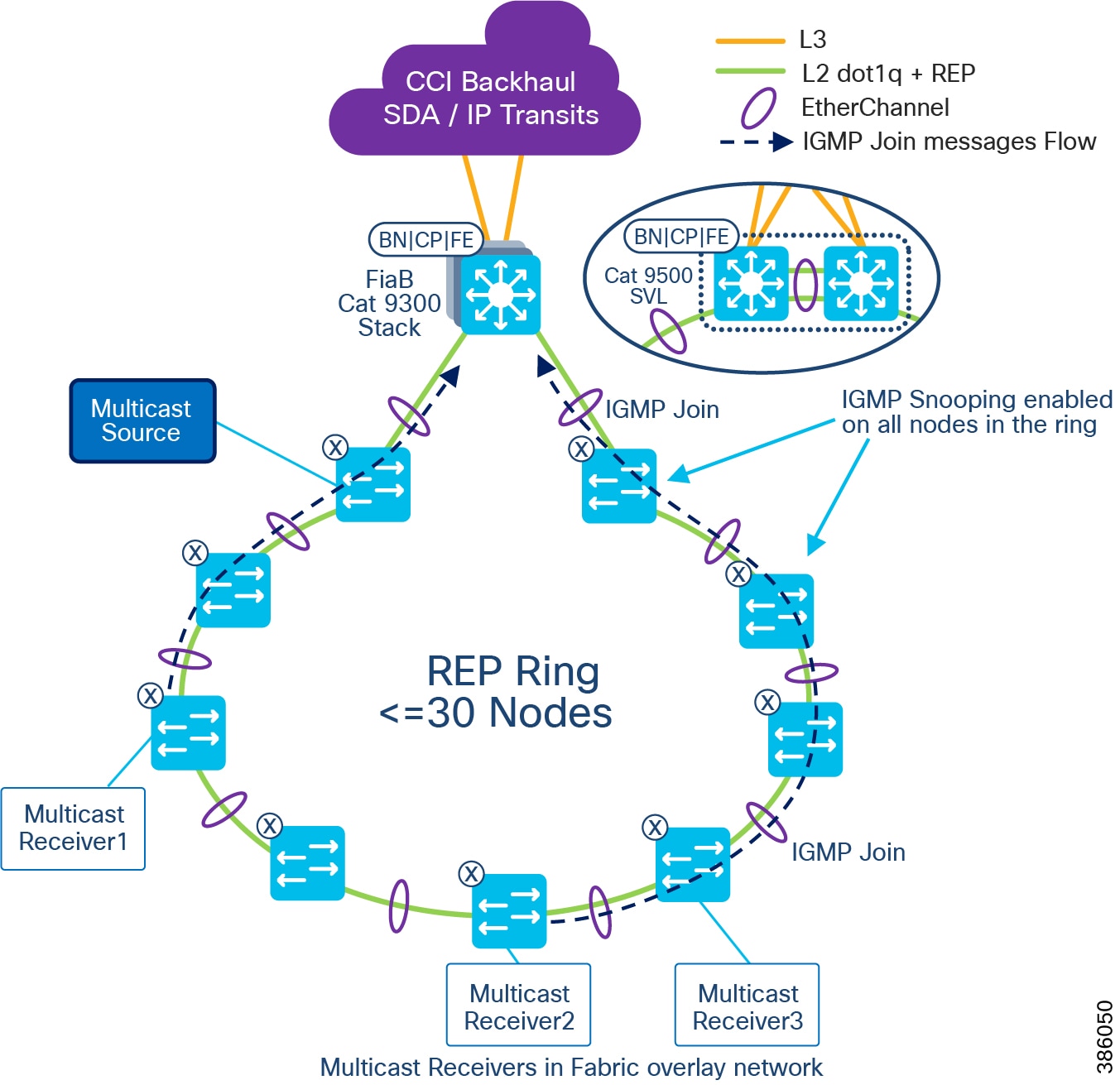
Figure 78 illustrates the multicast network design for PIM-ASM configured in fabric overlay, for multicast receiver(s) in the in the overlay network within a CCI PoP site and multicast source is outside of the fabric.
Figure 78 CCl Multicast PIM ASM – Multicast source outside of the Fabric

In case of SDA wireless multicast clients (receivers):
- The client sends IGMP join for a specific multicast Group (G).
- AP encapsulates it in VXLAN and send it to the upstream switch.
- The Fabric Edge node (FE) receives it and does a PIM Join towards the Fabric Rendezvous Point RP (assuming PIM-SM is used).
SD-Access Multicast Operation in PIM-SSM
- Multicast client (receiver) is in the overlay, multicast source can be outside Fabric or in the overlay as well
- PIM-SSM needs to be running in the Overlay
- The client sends IGMP v3 join for a specific multicast Group (G)
- The Fabric Edge node (i.e FiaB) receives it and since the IGMP v3 join has the source address information for that multicast group it sends a PIM Join towards the source directly. In our case since the source is reachable through the border it sends the PIM join to the border.
- The fabric RP is not needed in a PIM SSM deployment
- In an SSM deployment, the source address is part of IGMP v3 join the edge will ask the control plane for the location of the source address (IP to RLOC Table) and based on the reply will send the PIM Join in the Overlay to the destination node.
- If Border (i.e FiaB) registered that source, then the PIM join is directly sent to Border.
- If the source is not known in the fabric the PIM join is also sent to the border (i.e. FiaB) as Border is the default exit point of the fabric.
- From earlier, the FiaB (Border) knows clients which requested the specific multicast group and multicast traffic is sent to receivers connected to Edge or L2 access ring.
- It works similarly for SDA wireless deployment as well.
Figure 79 illustrates the multicast network design for PIM-SSM configured in fabric overlay, for multicast receiver(s) in the in the overlay network within a CCI PoP site and multicast source is outside of the fabric or in the overlay in the fabric.
Figure 79 CCl Multicast PIM SSM – Multicast source outside of the Fabric
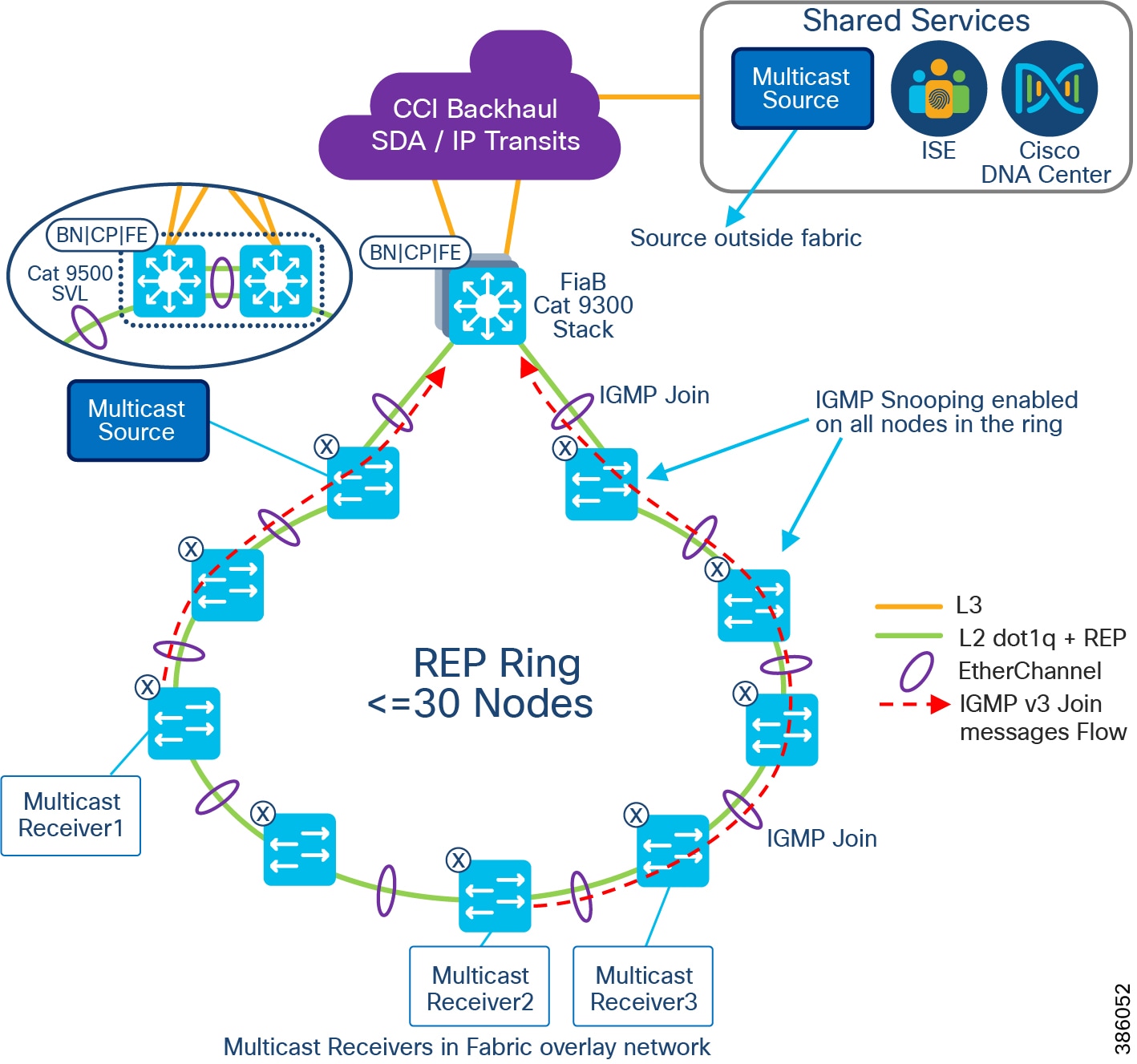
Note that RP is not needed in the fabric and multicast receivers sends IGMP v3 Join messages in PIM-SSM deployment.
Multicast Design between PoP Sites
CCI network multicast receivers could be on different PoP sites and the multicast source could be in a PoP site or HQ site. In this case, multicast traffic must be forwarded across PoP sites interconnected via transit network in CCI. This section covers the multicast forwarding design across CCI PoPs via IP transit and SD-Access transit network. IP trasnsit based multicast forwarding across fabric is recommended in CCI for multicast traffic forwarding across PoP sites in CCI network due to some limitations in SD-Access transit based multicast forwarding.
Because each fabric or PoP site is considered as one multicast region, configuring PIM-ASM with RP provisioned on each PoP site fabric border (i.e FiaB) via Cisco DNA Center and then configuring MSDP between RPs (connected via IP transit) for multicast traffic forwarding requires manual CLI configurations on fabric devices. Hence, it is recommended to configure PIM-ASM with RP external and common to all PoP sites in CCI network i.e Fusion Router, as shown.
IP Transit-based Multicast Design
Figure 80 CCl Multicast design across PoPs interconnected via IP Transit
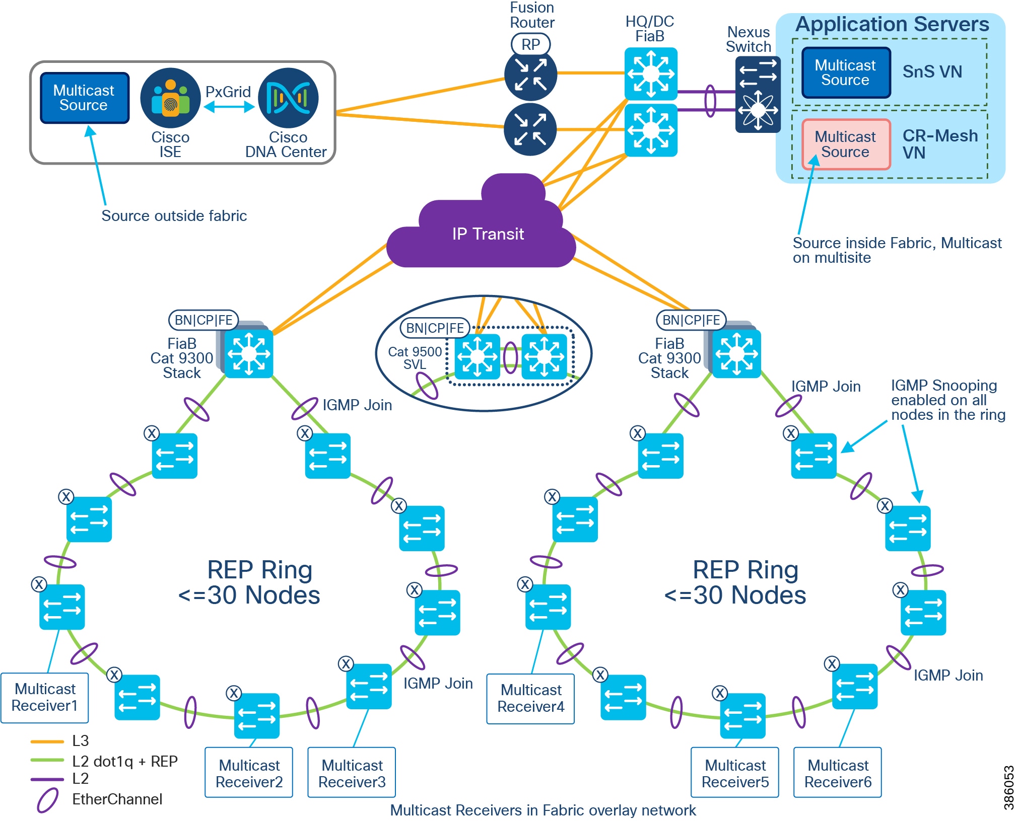
As shown in CCl Multicast design across PoPs interconnected via IP Transit, multicast is configured per Virtual Network (VN) on each PoP site with an external RP (RP on fusion router) common to all PoP site. A multicast source could be in HQ/DC site or shared services and receivers are in PoP sites. In this design, all IGMP messages from the multicast receiver(s) are forwarded to the central RP and RP anchors the multicast traffic forwarding to PoP sites where the receivers are connected as discussed in the section SD-Access Multicast operation in PIM-ASM.
SD-Access Transit-based Multicast Design
Multicast forwarding across CCI PoPs interconnected using SD-Access transit can be enabled using Cisco DNA Center. Refer to the section that follows for design considerations and limitations when enabling multicast across SD-Access transit per VN in the network.
Design Considerations & Limitations
- Rendezvous Point (RP) should be located outside of the CCI PoP or fabric site. Multicast forwarding over SDA transit is not supported if the RP is located within a PoP.
- The external RP is reachable from all PoPs border nodes connected to SDA Transit.
- The PoP Site is set to either head-end replication or native multicast; a mix of head-end and native cannot be supported.
- If all PoPs use native multicast, then the underlay between PoPs must support protocol independent multicast-source specific multicast (PIM-SSM).
- The multicast source must be in a CCI central or HQ site and receivers in a PoPs IE ring, as shown in Multicast over SD-Access Transit Network.
As shown in Multicast over SD-Access Transit Network, the RP is configured in a fusion router. The router is external to the fabric and a multicast source could be either within the fabric in the CCI HQ Application Servers network or outside of the fabric or PoP in shared services network. The multicast receivers are endpoints connected to IE switches in the CCI PoPs interconnected through the SD-Access transit network. Refer to the Multicast Design in a PoP Site for more details on the IGMP snooping configuration in the IE ring. The VN multicast across these PoPs is configured using the Cisco DNA Center workflow, as discussed in the CCI Implementation Guide.
Refer to the CCI Implementation Guide for the multicast over SDA transit configuration:
https://www.cisco.com/c/en/us/td/docs/solutions/Verticals/CCI/CCI/IG/cci-ig/cci-ig.html
Figure 81 Multicast over SD-Access Transit Network
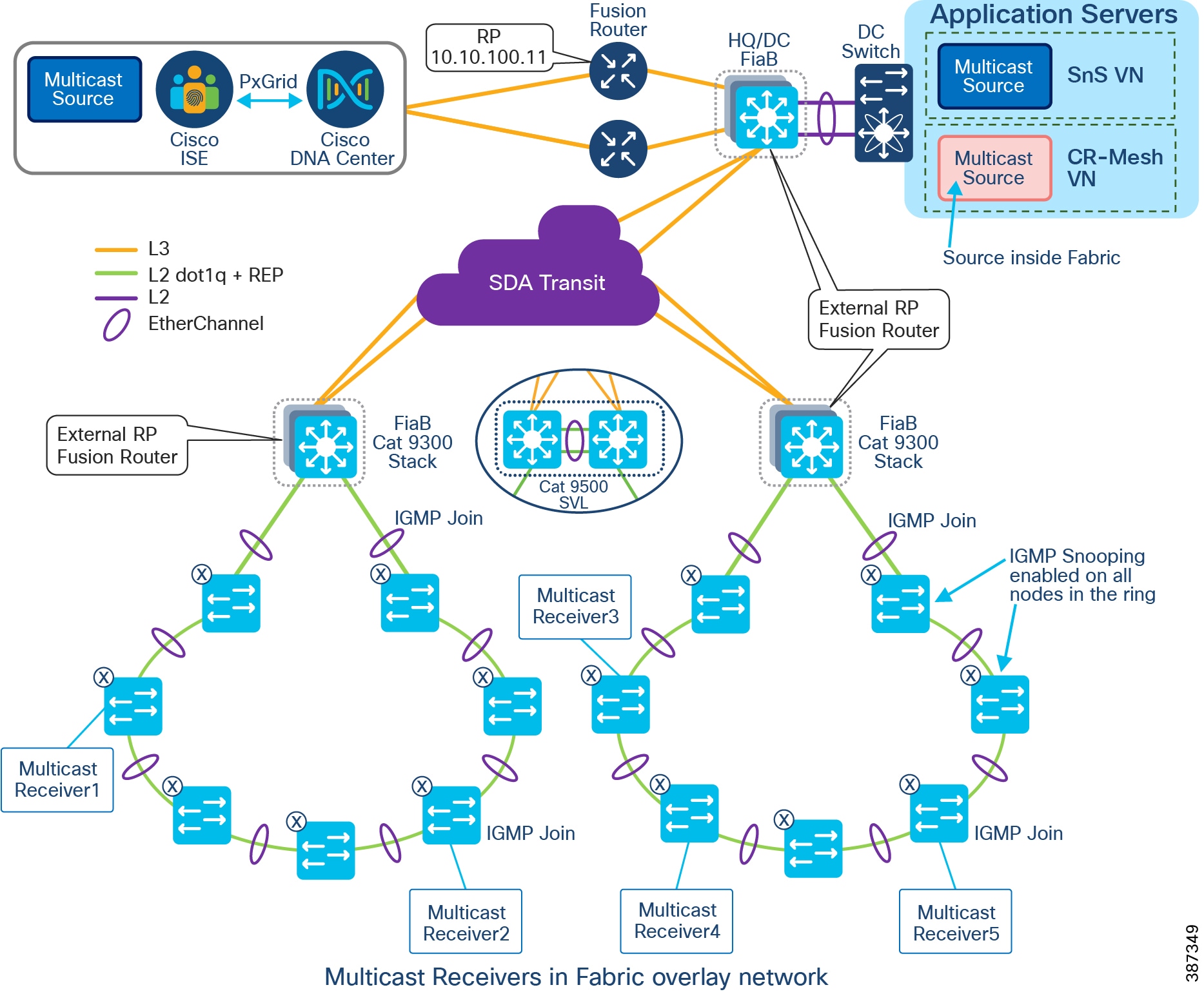
Network High Availability
Failure of any part of the network (either network device or network link) can affect the availability of services. The impact of availability increases with the increase in the aggregation level of the failing node/link. Availability is improved by avoiding a single point of failure by means of high availability (HA) or redundancy. Therefore, every critical component and link in the overall network should have HA or redundancy designed-in and configured.
This section, which discusses HA/redundancy design for the entire solution, includes the following major topics:
- High Availability for the Access Layer
- High Availability for the PoP Distribution Layer
- High Availability for the Super Core Layer
- High Availability for the SD-Access Transit
- High Availability for the Shared Services Switch
- High Availability for the Shared Services Servers
High Availability for the Access Layer
The access layer connectivity is provided with Cisco Industrial Ethernet (IE) switches and REP ring, as shown in CCI Major Building Blocks. REP ring connectivity provides redundancy for the uplinks of the access switches. REP ring network converges within 100ms and provides an alternate path in case of a link failure. EtherChannel using Port Aggregation Protocol (PAgP) is configured between the ENs or PENs and Fabric Edge/FiaB, providing redundancy and load balancing.
Endpoint redundancy can be provided by duplicating the critical endpoints covering specific locations such as a camera.
For redundancy of vertical service gateways, refer to their respective vertical sections.
High Availability for the PoP Distribution Layer
In the case of a FiaB setup, control plane, edge, and border node functionality are all placed on a single switch device. No additional fabric devices are required or permitted for the FiaB deployment; solution resiliency depends on the redundant switches in a stack.
9300 StackWise 480
Thus, high availability is provided at the distribution layer for the Cisco Catalyst 9300 (FiaB) by configuring Cisco StackWise-480 as shown in StackWise 480 on Catalyst 9300. Cisco StackWise-480 is an advanced Cisco technology with support for Non-Stop Forwarding with Stateful Switchover (NSF/SSO) for the most resilient architecture in a stackable (sub-50-ms) solution. For more details, please refer to the Cisco Catalyst 9300 Series Switches Data Sheet at the following URL:
- https://www.cisco.com/c/en/us/products/collateral/switches/catalyst-9300-series-switches/nb-06-cat9300-ser-data-sheet-cte-en.html
Figure 82 StackWise 480 on Catalyst 9300
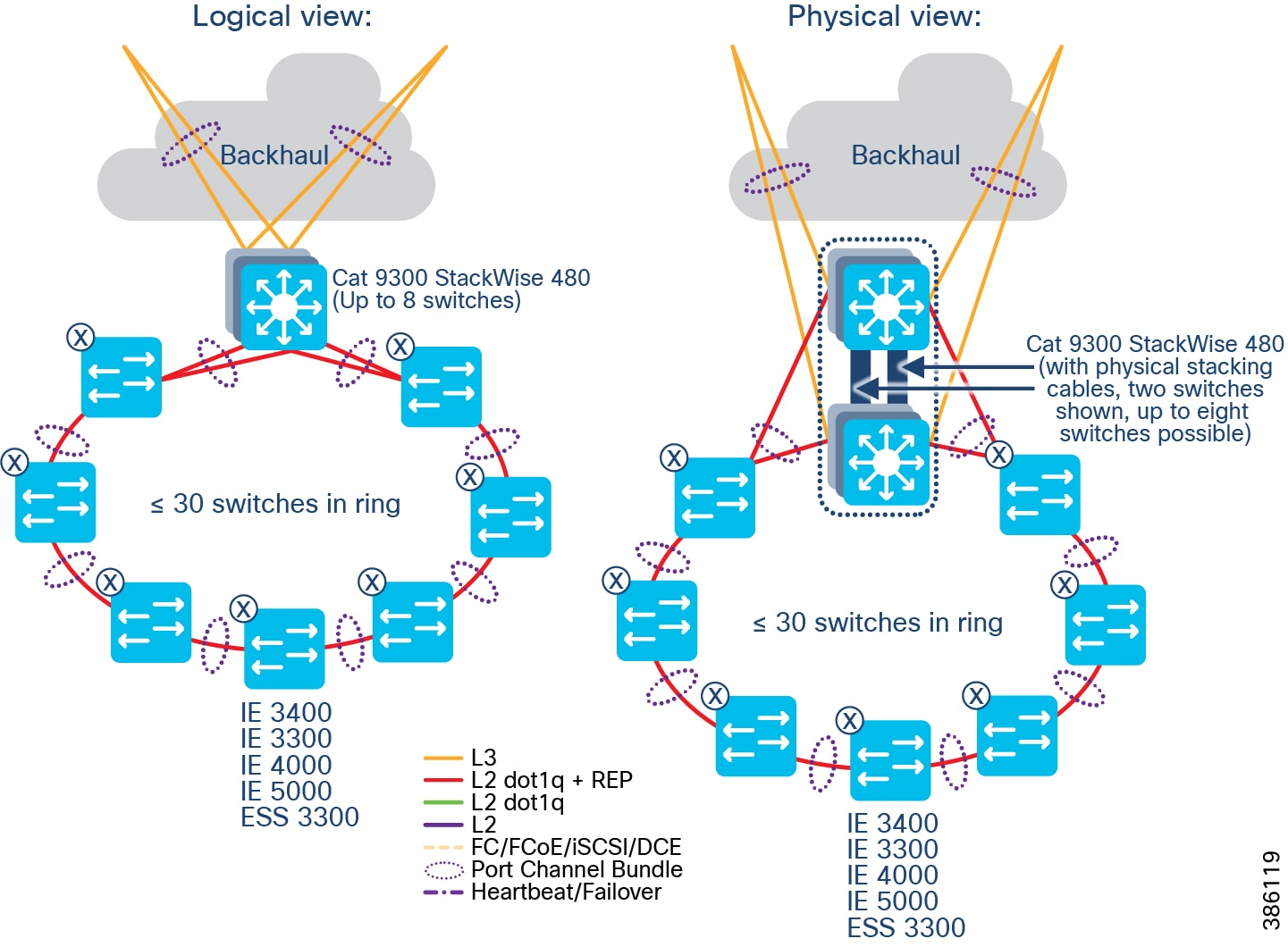
Please refer to the caveat recorded in the Implementation Guide for convergence time in case of stack active switch failover.
HA and load balancing are provided by EtherChannel between access switches and Cisco Catalyst 9300 (FiaB). If any of the switches or links fail, the operation will continue with no interruption. Two uplinks of an access switch are connected to two different switches in the stack. Multiple switches in a stack are in active-active redundancy mode; they appear as a single aggregate switch to the peer. Thus, EtherChannel/PortChannel is configured between access switches (IE switches/Nexus switches) and Cisco Catalyst 9300 stack.
Redundant Layer 3 uplinks are configured between distribution layer stack switches and core layer switches. Load balancing and redundancy are ensured by the routing protocols.
9500 StackWise Virtual
Cisco Catalyst 9500 differs from the Catalyst 9300 (StackWise 480) insofar as the 9300 has physical backplane stacking cables, with a maximum distance of 30ft/10m, whereas the Catalyst 9500 (StackWise Virtual) uses Ethernet interfaces, and can be split across much greater distances, typically several miles/kilometers for a CCI deployment. Doing so provides geo-redundancy, as the FiaB stack is split across two disparate physical locations, and therefore helps mitigate against local power problems, fiber cuts, etc.
Figure 83 StackWise Virtual on Catalyst 9500
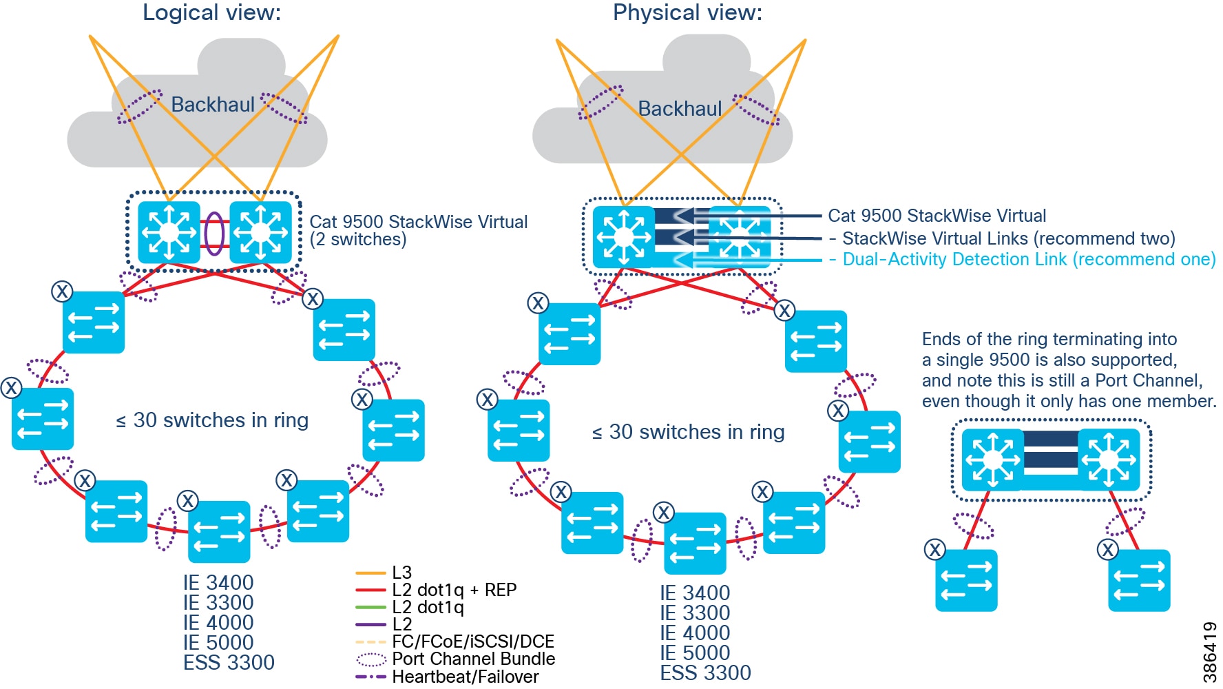
The StackWise Virtual Link (SVL) is typically comprised of multiple 10 or 40 Gbps interfaces (and associated transceivers (e.g. SFP+/QSFP) and cabling). These are dedicated to being SVL, provide a virtual backplane between the two physical Catalyst 9500 switches, and cannot be used for any other purpose. In CCI the design recommendation is two physical SVL links, and one Dual-Active Detection (DAD) link. The DAD link is there to mitigate against both stack members becoming active in a failure scenario; care must be taken for fiber physical paths between two separate locations – if all fibers are taking the same physical path, then a fiber cut will likely nullify any geo-redundancy gained by using SVL.
Sizing the SVL link(s) must be done with respect to the upstream and downstream network requirements. For example, if the upstream (transit) links are 10Gbps from each Catalyst 9500, then the SVL link should be 20Gbps or more.
It is recommended that the IE switches get connected to both stack members, using a Port Channel (which is automated by DNAC) as this results in lower L2 convergence times during failure conditions, however it is also supported to connect to just the nearest Catalyst 9500 stack member – this could be likely when there is insufficient fiber pairs between the two physical locations that each stack member is housed – however in this case a Port Channel is still used, even though it only has one bundle member; this aligns with SDA automation, and also allows the possibility of almost hitless upgrade should extra fiber capacity become available in the future.
For more details on SVL please refer to https://www.cisco.com/c/dam/en/us/products/collateral/switches/catalyst-9000/nb-06-cat-9k-stack-wp-cte-en.pdf and https://www.cisco.com/c/en/us/td/docs/switches/lan/catalyst9500/software/release/17-6/configuration_guide/ha/b_176_ha_9500_cg/configuring_cisco_stackwise_virtual.html
High Availability for the Super Core Layer
Two core switches are configured for redundancy. All connections/links to core switches (downlinks and uplinks) are duplicated. A Layer 3 handoff is chosen between the Fabric Border and the IP transit. The Cisco DNA Center configures BGP as the exterior gateway protocol. Dual-Homed BGP connection with multiple interfaces at the Fabric Border terminating at different core switches (IP Transit) can be configured by the Cisco DNA Center for redundancy and load sharing.
Routing protocols such as IS-IS/EIGRP/OSPF are configured in the underlay for connecting core switch and the shared services network switches (Nexus 5000 series). By default, both EIGRP and OSPF support Equal-Cost Multi Path (ECMP) routing. EIPGR/OSPF with ECMP provide redundancy and load balancing over multiple paths.
A cross link at each aggregation layer is used for optimal routing in case of an uplink failure. EtherChannel is configured between the core switches for cross-link communication (from uplink of one core switch to downlink of the other core switch) and to choose an alternate path in case of a link failure.
High Availability for the SD-Access Transit
Two switches are configured for SD-Access Transit for redundancy. All connections/links to SD-Access transit nodes (downlinks and uplinks) are duplicated. The Cisco DNA Center auto configures communication between Fabric Border and redundant SD-Access Transit nodes ensuring redundancy and load-balancing.
Routing protocols such as EIGRP/OSPF are configured in the underlay for connecting SD-Access Transit nodes and the fusion router. By default, both EIGRP and OSPF support ECMP routing. EIGRP/OSPF with ECMP provide redundancy and load balancing over multiple paths.
A cross link at each aggregation layer is used for optimal routing in case of an uplink failure. EtherChannel is configured between the SD-Access transit nodes for cross-link communication and to choose an alternate path in case of a link failure.
High Availability for the Shared Services Switch
Redundant Nexus 5000 series switches are configured for providing HA to the server connectivity. Nexus switches are configured with vPC PortChannel redundancy connecting to various servers in the shared services network such as Cisco DNA Center and ISE.
|
|
|
|---|---|
High Availability for the Shared Services Servers
Redundancy should be configured for various critical servers in the network, i.e., Cisco DNA Center, ISE, FND, DHCP, DNAC, and CA. The Cisco DNA Center supports inherent redundancy with cluster.
Cisco DNA Center Redundancy
The Cisco DNA Center redundancy is provided by clustering three Cisco DNA Center appliances together. Clustering provides a sharing of resources and features and helps enable high availability and scalability. The Cisco DNA Center supports a single-host or three-host cluster configuration.
The three-host cluster provides both software and hardware high availability. The three-node cluster can inherently do service/load distribution, database, and security replication. The cluster will survive loss of a single node.
The single host cluster does not provide hardware high availability. Therefore, we recommend three-host cluster configuration to be used for the CCI Network. Detailed configuration is provided in the Cisco DNA Center Administration Guide at the following URL:
https://www.cisco.com/c/en/us/td/docs/cloud-systems-management/network-automation-and-management/dna-center/2-2-3/ha_guide/b_cisco_dna_center_ha_guide_2_2_3.html
If the Cisco DNA Center appliance becomes unavailable, the network still functions, but automated provisioning and network monitoring capabilities are not possible until the appliance or cluster is repaired/restored.
Shared Services Application Servers Redundancy
Depending on the provisioning, UCS server level redundancy and/or application level redundancy can be configured for all critical application servers. Refer to the corresponding vertical sections for details.
Cisco ISE Redundancy
Cisco ISE has a highly available and scalable architecture that supports standalone and distributed deployments. In a distributed environment, you configure one primary Administration ISE node to manage the secondary ISE nodes that are deployed onto the network. Detailed information is provided in the Cisco Identity Services Engine Administrator Guide at the following URL:
https://www.cisco.com/c/en/us/td/docs/security/ise/3-0/admin_guide/b_ISE_admin_3_0/b_ISE_admin_30_deployment.html
NGFW Redundancy
Configuring high availability, also called failover, requires two identical Firepower Threat Defense devices connected to each other through a dedicated failover link and, optionally, a state link. Firepower Threat Defense supports Active/Standby failover, where one unit is the active unit and passes traffic. The standby unit does not actively pass traffic, but synchronizes configuration and other state information from the active unit. When a failover occurs, the active unit fails over to the standby unit, which then becomes active. The health of the active unit (hardware, interfaces, software, and environmental status) is monitored to determine if specific failover conditions are met. If those conditions are met, failover occurs.
Detailed information can be found in High Availability for Firepower Threat Defense at the following URL:
https://www.cisco.com/c/en/us/td/docs/security/firepower/70/configuration/guide/fpmc-config-guide-v70/high_availability_for_firepower_threat_defense.html
CCI Network Scale and Dimensioning
The CCI solution consists of the CCI access, distribution, core, data center, shared services, and DMZ layers. This section, which illustrates scaling considerations and available options at different layers of the network and provides steps for computing dimensions for an CCI network deployment, includes the following major topics:
- CCI Network Access, Distribution, and Core Layer Portfolio Comparison
- CCI Network Access Layer Dimensioning
- CCI Network Distribution and Core Layer Dimensioning
- Cisco DNA Center Scalability
- Cisco ISE and NGFW Scalability
CCI Network Access, Distribution, and Core Layer Portfolio Comparison
CCI Network Access, Distribution, and Core Layer Portfolio Comparison shows the portfolio of devices used at different layers of CCI Network. The “CCI role” row in the table indicates the layer at which the device family of switches are used and in which building block. While core and distribution exist in the Centralized Infrastructure, each PoP is effectively its own LAN. The Cisco Catalyst 9300 stack is a collapsed core and distribution, with access done on the Cisco Industrial Ethernet (IE) switches.
The Cisco Industrial Ethernet Portfolio switches that are used in the access layer are modular in size with various form factors, port sizes, and features. Thus, the CCI PoP access layer is highly scalable from a very small to very large size with a suitable quantity of Cisco Industrial Ethernet (IE) switches. Similarly, the Catalyst series of switches used in the distribution layer have several models suited to different deployment needs and they support stacking, thus are highly scalable. The switches used in the core layer suit central deployment with high density fiber ports and high switching (6.4 Tbps) capacity. A summary of these switches is given in CCI Network Access, Distribution, and Core Layer Portfolio Comparison as a reference, which can assist in the selection of suitable models based on deployment needs.
A comparison of the uplink capabilities of Cisco Industrial gateways suitable for CCI Remote PoP connectivity is shown in CCI Remote PoP and IoT Gateways Portfolio Comparison.
CCI Network Access Layer Dimensioning
In Requirements for Endpoints/Devices Connected to Access Layer Switch, we show different types of endpoints and gateways connected to CCI PoP access ports, along with their port type and bandwidth requirements. Based on the deployment needs of a site (e.g., number of cameras, number of IoT gateways), access port and access ring requirements can be computed using information in Requirements for Endpoints/Devices Connected to Access Layer Switch and StackWise Virtual on Catalyst 9500.
- Depending on the requirement of a specific site, the default bandwidth allocation in an access ring can be adjusted. For example, if only cameras are to be connected, the bandwidth allocated for camera traffic can be increased up to 900Mbps, thus approximately 150 to 300 cameras can be supported per ring.
- If the cumulative demand for various traffic generated from a ring is more than 1Gbps, separate rings can be laid to cater to the specific need.
CCI Network Distribution and Core Layer Dimensioning
The CCI system dimensioning chart is shown in StackWise Virtual on Catalyst 9500. Cisco Catalyst 9300 series switches have up to 48 ports and 8 switches can be stacked. Each ring including redundancy requires 4 ports for termination. With a minimum of 2 switches in a stack, up to 24 concurrent rings can be supported. Each ring can support up to 30 Cisco Industrial Ethernet (IE) switches. For further expansion, either additional switches can be added to the stack or additional PoPs can be created with a new stack of Cisco Catalyst 9300 series switches.
Every ring can generate traffic up to 1Gbps. Considering up to 24 concurrent rings, 24Gbps traffic is generated. The fixed uplink of Cisco Catalyst 9300 supports up to 4x10G and modular uplinks support 1/10/25/40G. Modular uplinks can also be added based on the necessity. As per standard Cisco QoS recommendation, the oversubscription ratio for distribution-to-core level is 4:1. However, considering most of the IoT traffic is device generated and is of constant bit rate, the oversubscription ratio at distribution-to-core should be kept low. Refer to Enterprise QoS Solution Reference Network Design Guide at the following URL:
- https://www.cisco.com/c/en/us/td/docs/solutions/Enterprise/WAN_and_MAN/QoS_SRND/QoS-SRND-Book/QoSDesign.html#wp998242
The core Cisco Catalyst 9500 series switches support 48 1/10/25 Gigabit ports. Each PoP with redundancy needs 2 ports for termination at the core. Thus, with a pair of Cisco Catalyst 9500 series switches, up to 40 PoP locations can be supported (remaining ports are needed for uplink connection to Shared Services, Application Servers, and Internet). Further expansion can be done with additional Cisco Catalyst 9500 series switches. The Cisco Catalyst 9500 switches have very high (6.4Tbps) switching capacity. If the connection from Distribution to Core passes through intermediate nodes (IP/MPLS backhaul), the number of ports needed at the Core can be reduced. As per the standard Cisco QoS recommendation, the over-subscription at core layer should be 1:1, resulting in no over-subscription.
Thus, the CCI access, distribution, and core systems can be scaled from a small deployment to a large deployment in terms of number of endpoints connected, bandwidth requirement, and area to be covered.
The scale numbers are summarized below:
- Max number of access ports per node (IE switch): 20 (IE 4000), 26 (IE 3x00), 28 (IE 4010/5000), or 24 (ESS 3300)
- Max number of nodes per ring: 30
- Max bandwidth of an access ring: 1Gbps
- Max number of concurrent access rings per PoP (one pair of 9300): 24
- Max number of concurrent access rings per PoP (one pair of 9500): 48
- Max number Cisco Catalyst 9300 switches in a stack: 8
- Max number of Cisco Catalyst 9500 switches in a StackWise Virtual: 2
Figure 84 Infrastructure with and without CCI Ethernet Horizontal and Redundancy
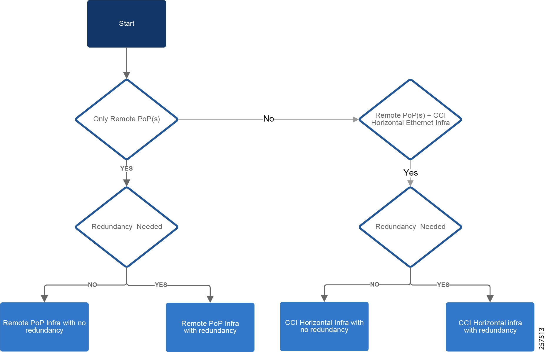
- For Remote PoP infrastructure requirement, refer to Infrastructure with and without CCI Ethernet Horizontal and Redundancy.
CCI Network SD-Access Transit Scale
In the case of SD-Access Transit, the PoP sites are connected to SD-Access Transit. Similar to the one shown in Infrastructure with and without CCI Ethernet Horizontal and Redundancy, when the number of PoP sites pass 40, an additional pair of SD-Access Transit sites can be added to accommodate required ports and bandwidth.
Cisco DNA Center Scalability
The Cisco DNA Center scaling computation and hardware specification is given in the Cisco DNA Center data sheet. Cisco DNA Center numbers are per instance, which can be a single-node cluster or a three-node cluster. The maximum numbers are either the platform absolute limits or the recommended limit based on the most current testing of a single platform. Refer to Cisco Documentation for further details on scaling and sizing of Cisco DNA Center documentation.
For more information about Cisco DNA Center scaling, refer to the Cisco DNA Center User Guide at the following URL:
https://www.cisco.com/c/en/us/td/docs/cloud-systems-management/network-automation-and-management/dna-center/2-1-2/user_guide/b_cisco_dna_center_ug_2_1_2.html
Cisco ISE and NGFW Scalability
Cisco ISE scaling is based on deployment model such as standalone or distributed. For more details, refer to the Cisco Identity Services Engine Installation Guide, Release 2.4 at the following URL:
Cisco NGFW scaling factor includes platform configuration and features enabled. For more details, refer to the Cisco documentation Deploy a Cluster for Firepower Threat Defense for Scalability and High Availability at the following URL:
Conclusions
Digital transformation for cities, communities, and roadways form the basis for future sustainability, economic strength, operational efficiency, improved livability, public safety, and general appeal for new investment and talent. Yet these efforts can be complex and challenging. Cisco Connected Communities Infrastructure is the answer to this objective and is designed with these challenges in mind.
In summary, this Cisco Connected Community Infrastructure (CCI) solution Design Guide provides an end-to-end secured access and backbone for cities, communities, and roadway applications. The design is based on Cisco's Intent-based Networking platform: the Cisco DNA Center. Multiple access technologies and backbone WAN options are supported by the design. The solution is offered as a secure, modular architecture enabling incremental growth of applications and network size, making the solution cost effective, secure, and scalable. Overall, the design of CCI solution is generic in nature, enabling new applications to be added with ease. Apart from the generic CCI solution design, this document also covers detailed design for the Smart Lighting solution, Safety and Security solution, and frameworks for Public and Outdoor Wi-Fi and LoRaWAN based solutions.
"Every smart city starts with its network. I want to move away from isolated solutions to a single multi-service architecture approach that supports all the goals and outcomes we want for our city."
Acronyms and Initialisms
The following table summarizes all acronyms and initialisms used in the Cisco Connected Communities Infrastructure Solution Design Guide:
|
|
|
|---|---|
enhanced fault, configuration, accounting, performance, and security |
|
|
|
|
|
|
|
 Feedback