University Solution Overview
The purpose of this document is to provide guidance and serve as a validated reference for a university deployment using the Cisco DNA Center and Cisco Software-Defined Access solutions.
Significant changes have been taking place in the education industry, such as smart campus and automation, hybrid learning spaces, and secure distance learning. There is an exponential growth in the number of endpoints connecting to the network with students and faculty bringing in their own devices to the campus. University students and faculty members travel to other universities around the world and need instant access to their research materials. Education network environments, like any other industry vertical, need enhanced network services, seamless mobility, network high availability, and efficient network management. University networks also have a specialized set of demands that includes enhanced security for residential services, wireless-heavy networks, and wireless mobility.
Keeping the education industry needs in mind, the following sections describe the key considerations for a University Vertical.
Cisco DNA Service for Bonjour
The Cisco DNA Service for Bonjour is developed on a software-defined controller-based solution that enables network-wide distributed devices to advertise and discover Bonjour services across Layer 3 network boundaries. The distributed service-oriented architecture is designed to have isolated flood boundaries with service-policy enforcement points at the network edge and to enable end-to-end services management. The solution provides complete seamless integration into existing complex enterprise network designs, while retaining the end user experience in mobile printing, screen sharing, file sharing, and other services consistent between home and university networks.
Education Roaming (Eduroam)
Eduroam provides network access to researchers, faculty members, and students when visiting a foreign institution. Users connect to the Eduroam Wi-Fi network anywhere in the world and use their home institution credentials for authentication. After successfully authentication, visitors gain instant network access. Eduroam is also seen as a replacement for guest services. The institution does not have the overhead of authenticating and managing guest access, thus eliminating significant administrative overhead.
Bring Your Own Device (BYOD)
As more personal devices become prevalent in a university campus, students are using these devices to access secured resources and applications to do their daily activities. Cisco Identity Services Engine (ISE) offers the BYOD functionality. Students can add their personal devices to the network by running native supplicant provisioning or by adding the devices to the My Devices portal. University administrators can ensure the security of the network by enforcing posture policies in the BYOD devices.
Guest Services Using Multisite Remote Border
A university network design is remarkably similar to most campus network designs. Colleges and universities must be able to support thousands of students who are all simultaneously connecting to the network. Apart from the students and faculty, there is also a need for guest users to access the network. Guest access is needed for visitors, event attendees, and so on.
Most guests access campus network services wirelessly and are limited to only those services that are publicly available. By setting up a separate virtual network (VN) for guests, access is limited usually to the internet via the DMZ. The number of sites may be many for a university and the best design is to have all the guest virtual networks that extend across multiple sites terminate at the DMZ. This design is achieved using the Anchor VN feature (also known as the Multisite Remote Border feature). This feature allows for an egress preference per VN. All guest traffic that extends across multiple sites can be contained in one VN and terminated at a common remote border.
Service and Network Resiliency
The university network cannot afford to have any downtime. As such, these networks require strict network- and service-level resiliency. Network-level resiliency can be achieved using a robust fabric network design that includes dual fabric borders nodes, dual fabric control plane nodes, dual anchor borders and control plane nodes, dual wireless controllers, fabric switches with hardware stacking, and dual fabric transit control plane nodes where applicable. Service-level resiliency is achieved using a Cisco DNA Center three-node cluster as and a distributed Cisco ISE cluster with multiple Policy Administration Nodes (PANs), Monitoring Nodes (MNT), an active and standby Platform Exchange Grid (pxGrid), and Policy Service Nodes (PSN).
Network Management and Visibility
Network administrators should be able to efficiently manage and monitor their networks to quickly respond to the dynamic needs of the educational network. Using telemetry, the deployment should proactively predict network- and security-related risks and improve the performance of the network, devices, and applications. Cisco DNA Assurance, with the use of Cisco AI Network Analytics, collects telemetry data, monitors the performance and health of network devices, flags any issues that it detects, and offers remediation steps.
With Cisco DNA Assurance, administrators can monitor the overall health of the network devices and connected endpoints (both wired and wireless). Network and application assurance can be used to determine the individual health of the devices, endpoints, and their applications. With this deeper level of 360-degree analytics, administrators can identify the individual issues that network elements are having, such as connectivity challenges of any endpoints in a network.
Security and Network Segmentation
Education, like other industry sectors, needs to protect student and faculty information, university research data, financial information, and so on. Universities need to efficiently deploy and segment the network to achieve the needed security structure and isolation between critical data and common data.
Within the Cisco SD-Access architecture, Cisco DNA Center and Cisco ISE work in unison to provide the automation for planning, configuration, segmentation, identity, and policy services. Cisco ISE is responsible for device profiling, identity services, policy services, and dynamically exchanging information with Cisco DNA Center.
Cisco SD-Access addresses the need for complete data and control plane isolation by using macro-segmentation. By creating and placing users and devices into different overlay virtual networks (VNs), universities can achieve complete data isolation and can provide security among different departments and users.
Critical VLAN was added to address the situation where the fabric edges are unable to reach the configured RADIUS servers due to an outage, such as a WAN outage. During this outage, authentications are not possible for newly connecting endpoints. The Critical VLAN feature creates a fallback VLAN so that endpoints can successfully onboard and receive some level of access, such as emergency services during the temporary outage.
Cisco SD-Access can further address the need for a more granular data plane isolation between endpoints within the same VN using micro-segmentation via Scalable Group Tags (SGTs) for Group-Based Policy (GBP). Cisco DNA Center allows IT administrators to create groups and place users, devices, and IoT devices in groups according to their roles. IT administrators can then define policies that control how these groups can interact with each other and among themselves.
Cisco AI Endpoint Analytics
Modern security threats seek vulnerable points of entry to exploit the entire enterprise network data. After an entry point is breached, lateral movement from device to device can spread in mere seconds. University networks are populated by a wide variety of devices across multiple locations, which makes finding and identifying all the devices on a network a time-consuming and tedious effort. Cisco AI Endpoint Analytics addresses this issue by identifying the devices by type, manufacturer, model, OS type, communication protocols, and ports. Using passive network telemetry monitoring and deep packet inspection, Cisco DNA Center scans the network and allows an administrator to create profiling rules to classify devices based on those attributes. Coupled with machine learning, Cisco DNA Center can detect spoofed endpoints and assist an administrator to take effective actions on spoofed endpoints.
Cisco AI Endpoint Analytics has multiple methods to detect malicious endpoints. It uses change-in-profile labels, NAT mode detection, concurrent MAC address identification, posture, authentication method, and machine learning to identify and flag spurious endpoints. An overall trust score is generated for every endpoint. The trust score is a weighted average of multiple risk scores. A lower trust score indicates a higher risk for an endpoint.
Furthermore, Cisco DNA Center and Cisco ISE share the endpoint classification attributes. When new devices onboard through identity-based authentication, they can be automatically identified by manufacturer and type and added to the appropriate group. Defining and enforcing security policies are easier when applied to groups rather than to individual endpoints. Group-based policy can be edited more easily to adapt to new circumstances, such as security breakage by endpoints, and applied globally to the entire network.
Layer 2 Guest Termination Outside the Fabric
Customers sometimes need to have Layer 2 level traffic inspection for guests who are using the network. This requirement means that the first hop for all guest traffic needs to be outside the fabric. This implementation is achieved using a combination of Cisco DNA Center and manual device configuration. While the guest traffic is VXLAN-encapsulated and passes through the fabric, the first hop or gateway for guest traffic is outside the fabric.
Hardware and Software Specifications
The solution is tested with the hardware and software listed in the following table. See Cisco Software-Defined Access Compatibility Matrix for a complete list of supported hardware.
| Role | Model Name | Hardware Platform | Software Version | Software Version |
|---|---|---|---|---|
|
Cisco DNA Center Appliance |
DN2-HW-APL-XL |
Cisco DNA Center 3-Node High Availability Cluster |
2.3.3.7 |
2.3.5.5 |
|
Identity Management, RADIUS Server |
ISE-VM-K9 |
Cisco Identity Services Engine Virtual Appliance |
3.0 Patch 6 3.1 Patch 3 |
3.0 Patch 6 3.1 Patch 3 |
|
Cisco SD-Access Fabric Control Plane Node |
ASR1001-X |
Cisco 1000 Series Aggregation Services Routers |
17.6.4, 17.9.2a, 17.6.6a, 17.9.4a |
17.6.5, 17.9.4, 17.6.6a, 17.9.4a |
|
C9500-24Y4C C9500-24Q |
Cisco Catalyst 9500 Series Switches |
17.6.4, 17.9.3, 17.6.6a, 17.9.4a |
17.6.5, 17.9.4, 17.6.6a, 17.9.4a |
|
|
Cisco SD-Access Fabric Border Node |
ASR1006-X (RP3) |
Cisco 1000 Series Aggregation Services Routers (RP3) Processor |
17.6.5a, 17.9.4a |
17.6.5a, 17.9.4a |
|
C9500-24Y4C C9500-40X C9500-24Q |
Cisco Catalyst 9500 Series Switches |
17.6.6a, 17.9.4a |
17.6.6a, 17.9.4a |
|
|
Cisco SD-Access Fabric Edge Node |
C9300-48P C9300-24P |
Cisco Catalyst 9300 Series Switches |
17.6.6a, 17.9.4a |
17.6.6a, 17.9.4a |
|
Cisco SD-Access Wireless Controller |
C9800-80 C9800-CL |
Cisco Catalyst 9800-80 Wireless Controller Cisco Catalyst 9800-CL Wireless Controller |
17.6.6a, 17.9.4a |
17.6.6a, 17.9.4a |
|
Cisco SD-Access Extended Node |
WS-C3560CX-8XPD-S Cisco IE-4000 |
Cisco Catalyst 3560-CX Cisco IE 4000 Series |
15.2(7)E3 |
15.2(7)E3 |
Solution Use Case Scenarios
The following use cases were executed for the University Vertical profile using the topology shown in Figure 1.
Intent-based Networking Using Cisco DNA Center
Administrators can achieve the following:
-
Design global network hierarchy and global- and site-level network settings.
-
Automatically provision the devices.
-
Deploy the main campus network with dual borders and dual control plane nodes for redundancy and scale considerations.
-
Flexibly expand the main campus and satellite campus sites by onboarding the following types of new devices:
-
Fabric edges using zero-touch plug-and-play LAN Automation or using existing IP/MPLS infrastructure for underlay reachability.
-
Additional classic-extended nodes into the fabric for IoT device connection using zero-touch plug-and-play
-
Additional policy-extended nodes into the fabric with direct support of SGT and enhanced traffic enforcement
-
-
Connect distributed-campus sites using Cisco SD-Access transit for shared data-center and internet services
Multitier Security To Protect Sensitive Institutional Data
Administrators can achieve the following:
-
Segment students, faculty, guests, IoT, and campus devices into their right logical network to limit the movement of threats around the network.
-
Enable closed auth onboarding (dot1x) or MAC Authentication Bypass (MAB) for wired and wireless endpoints to prevent un-authorized access.
-
Provide tighter security, administrators on Cisco DNA Center can apply trusted CA FQDN-based certificates.
-
Create groups, place users and endpoints in those groups according to their identities, and define group-based policies that control traffic between groups.
-
Monitor Cisco DNA Center activities using audit logs which record system events that occurred, when and where they occurred, and which users initiated them.
-
Create granular role-based users with different privileges to access Cisco DNA Center.
Eduroam
Administrators can achieve the following:
-
Provision Eduroam Wi-Fi SSID with WPA2-enterprise enabled and 802.1X using Cisco DNA Center.
-
Configure the Cisco ISE to handle authentication requests from external Eduroam servers and forward the external user authentication requests to the Eduroam server.
-
Allow external users from foreign universities to connect to the Eduroam SSID on their local campus and gain network access upon successful authentication.
-
Allow traveling users from the local university to connect to the Eduroam SSID at foreign universities and gain network access.
Cisco Wide Area Bonjour
Administrators can achieve the following:
-
Configure SDG-Agents and network information to enable service-routing.
-
Configure service Policy-Based ZeroConf Services management and Common Bonjour Services distribution from end-user devices through the Cisco Wide Area Bonjour application.
-
Allow users of the university network to take advantage of Bonjour services, like printing and screen sharing across Layer 3 domains.
-
Use the Cisco Wide Area Bonjour dashboard for SDG-Agent statistics per subdomain-level services count and policy operational status.
Bring Your Own Device (BYOD)
Administrators can achieve the following:
-
Configure Cisco ISE to give privileged access to personal devices in the university network.
-
Provision WPA-2 Enterprise SSID for BYOD endpoints using Cisco DNA Center.
-
Allow students or faculty members to connect their own personal devices to the university network and gain privileged access.
-
Use the My Devices Portal in Cisco ISE to manage the BYOD endpoints.
Cisco AI Endpoint Analytics
Administrators can achieve the following:
-
Configure Cisco AI Endpoint Analytics to detect spoofed endpoints based on classification and behavioral model learning.
-
Configure Cisco DNA Center to detect and flag compromised endpoints. A comprehensive trust score is calculated for the endpoint based on the configured influencing parameters.
-
View the trust score and type of threat, and take corrective action or quarantine the malicious endpoint.
Guest Services with Multisite Remote Borders
Administrators can achieve the following:
-
Configure the guest VN and share it across multiple sites. This VN can be anchored at the remote border in an anchor site. Guest traffic is isolated in a guest VN and tunneled to anchoring borders for internet access.
-
Configure the common guest subnet to onboard guest users across the anchor and inherited fabric sites.
-
Provision a Guest SSID with CWA using Cisco DNA Center. The Guest SSID is common across all sites.
-
Implement an Anchor Site with dual anchor borders and control planes in physically distinct locations to provide redundancy if network failure occurs.
Service and Network Resiliency
Administrators can achieve the following:
-
Achieve High Availability throughout the network with dual Cisco SD-Access borders, dual control plane nodes, a border/edge stack, a port channel in the underlay, and dual transit control planes in the transit network. Failover and recovery of network failure should have no or a minimum interruption for traffic flows.
-
Implement a network that can recover from device or link failure automatically with minimal impact on existing applications, traffic, and users.
-
Configure Cisco DNA Center in 3-node High Availability mode. In this way, if there is a services or node failure, the Cisco DNA Center cluster can recover without the administrator's intervention.
-
Configure Cisco ISE in a distributed deployment model with PAN, PSN, and pxGrid service failover.
-
Backup the Cisco DNA Center configuration and data on-demand or on a schedule. The backup file can be restored onto Cisco DNA Center to reinstate previous Cisco DNA Center configurations.
Simplified Management
Administrators can achieve the following:
-
Use Cisco DNA Center for central management of device inventory using device information, including IPs, software releases, provision status, and inventory insights.
-
Create VNs across the organization to achieve consistent macro segmentation.
-
Apply multiple SGTs for a single VN and create group-based access policy for micro segmentation traffic within a VN.
-
Add or remove new groups of users using an add and remove VN function, and then associate or disassociate the IP gateway to the VN.
-
Use the Cisco DNA Center Software Image Management (SWIM) function to upgrade switches, routers, and wireless controllers to a selected golden image.
-
Configure VLAN consumption and optimization of the site border Layer 3 handoff to have the flexibility of VLAN assignment in a scaled multi-site environment.
Monitor Network and Clients Using Cisco DNA Assurance and Analytics
Administrators can achieve the following:
-
Use Cisco DNA Assurance to monitor network health and identify network issues. Cisco DNA Assurance can report issues triggered by various network failures including link down, AP down, and switch stack member down.
-
Use Cisco DNA Assurance to monitor wired and wireless client health and identify client onboarding issues.
-
Monitor a large number of wireless endpoints with Cisco DNA Assurance charts that show 100,000 concurrent endpoints and 250,000 transient endpoints.
-
View rogue APs in Cisco DNA Assurance and generate rogue AP reports.
Layer 2 Guest Termination Outside the Fabric
Administrators can achieve the following:
-
Configure the guest network using Cisco DNA Center.
-
Terminate guest traffic outside the fabric for Layer 2 level traffic inspection with a few manual device configuration changes.
Solution Environment
The solution test environment includes both topology and scale.
Topology
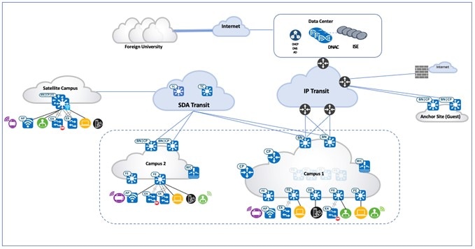
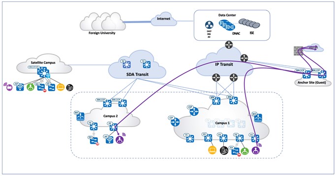
The test topology for the University Vertical includes a three-node Cisco DNA Center cluster to manage one large-scale main campus site, one medium-scale campus site, and one anchor site. Cisco SD-Access Transit is deployed to connect these distributed campuses. The following figure illustrates the logical topology of the University Vertical solution test bed.
The test bed setup has the following components:
-
Campus 1 site has dual borders, dual dedicated control plane nodes, dual WLCs, and 1000 fabric edges.
-
Campus 2 site has dual co-located border and control plane nodes, a WLC, fabric edges, and extended nodes.
-
Satellite campus site is a small site that has Fabric-in-a-Box on hardware stacking with an embedded WLC and extended nodes.
-
Anchor site has dual co-located anchor borders and control plane nodes, and provides anchored guest services across multiple fabric sites.
-
SD-Access Transit is implemented with dual Transit Control Plane nodes. Large campus site borders are configured to provide internet access to other campus sites via SD-Access Transit.
Scale
The following table shows the scale values that were tested. For the hardware capacity, see the Cisco DNA Center Data Sheet.
| Category | Value |
|---|---|
|
Device Inventory |
2000 |
|
Devices per Fabric Site |
600 |
|
Buildings and Floors |
3000 |
|
VNs per Fabric Site |
64 |
|
IP Pools per Fabric Site |
500 |
|
WLCs per Fabric Site |
2 |
|
Fabric Sites |
4 |
|
APs in Inventory |
8000 |
|
Endpoints |
100,000 (80,000 Wireless, 20,000 Wired) |
|
SSIDs |
8 |
|
SDGs |
25 |
|
Bonjour Service Instances |
16000 |
Solution Key Notes
This section describes the key technical notes of the solution validation for the University Vertical profile.
Cisco Wide Area Bonjour
The Cisco Wide Area Bonjour application is a software-defined, controller-based solution that enables devices to advertise and discover Bonjour services across Layer 2 domains, making these services applicable to a wide variety of wired and wireless enterprise networks. The Cisco Wide Area Bonjour application also addresses problems relating to security, policy enforcement, and services administration on a large scale. The new distributed architecture is designed to eliminate mDNS flood boundaries and transition to unicast-based service routing, providing service policy enforcement points and enabling the management of Bonjour services. With the Cisco Wide Area Bonjour application, you can seamlessly introduce new services into the existing enterprise environment without modifying the existing network design or configuration.
The Cisco Wide Area Bonjour is a non-default application of Cisco DNA Center. Download and install the application from the Cisco catalog server. After you successfully install the Cisco Wide Area Bonjour application, you can access it from the Cisco DNA Center home page by clicking the menu icon and then Tools.
The Cisco Wide Area Bonjour application on Cisco DNA Center does not push configurations to the Service Discovery Gateway (SDG) agent switches or service peer devices. The SDG agents and service peers need to be configured either manually or through templates created by the template editor in Cisco DNA Center.
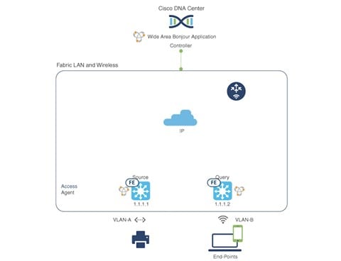
This section provides a Cisco Wide Area Bonjour use case that depicts a university where fabric edge switches provide printer services to remotely connected wireless users over a fabric-enabled wireless network. Wireless endpoints can discover the printer services, which are present in another building or campus site. A student or faculty member can initiate a print service request from a remote location, without being present physically in the building where printer is located. The following figure illustrates a Cisco Wide Area Bonjour solution. The network topology has Cisco SD-Access LAN and fabric mode wireless networks with Bonjour source and receiver in virtual network environments.
The first step is to implement global service filters, which permit the Cisco Wide Area Bonjour application to dynamically discover and distribute service information between trusted Cisco Catalyst SDG Agent switches across IP networks.
Create Service Filter: From Cisco Wide Area Bonjour application, select the service domain where the administrator wants to add the service filter and select the service types to permit announcements and queries. The administrator can edit, enable, or disable this setting after it is created.
Configure Source SDG Agents: From the Cisco Wide Area Bonjour application, select the SDG Agent and VLAN that announces the services. Administrators have the option to enable or disable the services for an IPv4 or IPv6 network.
Configure Query SDG Agent: From the Cisco Wide Area Bonjour application, select the SDG Agent and VLAN that receives queries for the services (Printer). Administrators have the option to enable or disable the services for an IPv4 or IPv6 network.
 Note |
You need to enable Global Wireless Multicast Mode in the Cisco Catalyst 9800 Series WLC. By default, the Cisco WLC and access points prevent forwarding Layer 2 or Layer 3 multicast frames between wireless and wired network infrastructure. |
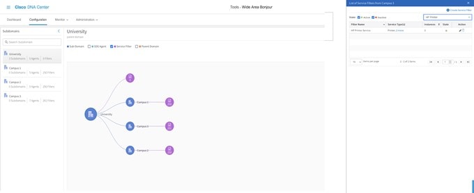
If the service filter status is green, the policy is active. When a user laptop onboards from any remote location in VLAN-B, it can discover and use the printer services in VLAN-A. The following figure illustrates the Cisco Wide Area Bonjour dashboard in Cisco DNA Center.
Eduroam
Eduroam is a global wireless network access service for research and education. Eduroam provides researchers, faculty, and students with network access when visiting a foreign institution. The Eduroam service uses IEEE 802.1X as the authentication method and a hierarchical system of participating RADIUS servers. The home and foreign institution radius servers need to be subscribed to a network of participating Eduroam servers.
Students connect to the Eduroam Wi-Fi network anywhere in the world and use their home institution credentials for authentication. Authorization to access the internet and other resources are handled by the institution being visited.
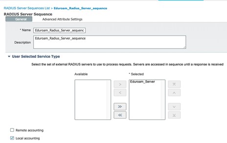
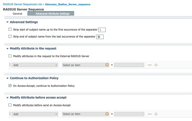
Eduroam Wi-Fi SSID is enabled with WPA2-enterprise, and 802.1X is provisioned using Cisco DNA Center. The configuration to implement Eduroam needs configurations on both Cisco ISE and Cisco DNA Center. The Eduroam policy sets and external radius server configurations are done in Cisco ISE. Figure 4 and Figure 5 show the Eduroam external server configuration.
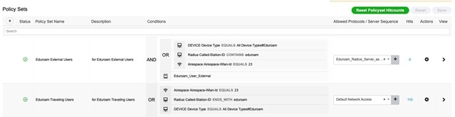
The following figure shows the Eduroam policy set configuration.
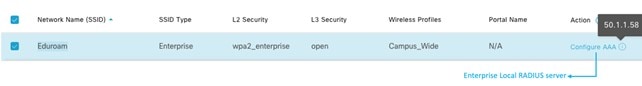
The following figure shows the Eduroam SSID configuration on Cisco DNA Center.
Eduroam has the following two main use cases:
-
External User: In this scenario, a student or faculty member belongs to a foreign university, and is visiting a local campus. The user connects to the Eduroam SSID and provides the credentials of their home institution. The authentication request is proxied to the Eduroam servers, which in turn forwards the request to the user’s home institution. After successful authentication, the user is granted network access. The following figure shows the authentication flow.
Figure 8. External User Authentication Flow 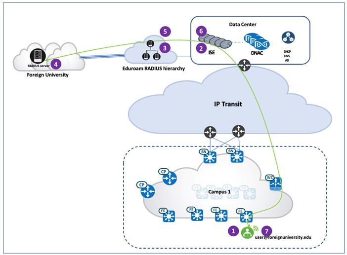
-
Traveling User: In this scenario, the student or faculty member belongs to the home institution but is physically located at the foreign university campus. When this user connects to the Eduroam SSID at the foreign university, the authentication request is sent to the Eduroam RADIUS server, which in turn forwards the request to the user's home institution. If the authentication is successful, the home RADIUS server sends a "Access Accept" response to the Eduroam server, and the Eduroam server forwards this response to the foreign university. The user is authenticated and gains network access at the foreign university. The following figure shows the authentication flow.
Figure 9. Traveling User Authentication Flow 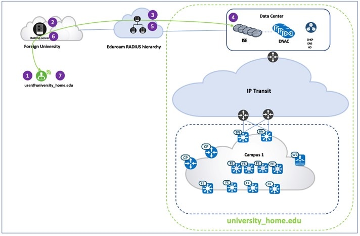
Bring Your Own Device (BYOD)
Cisco ISE offers the Bring Your Own Device (BYOD) functionality where students and faculty members can add their personal devices to the network by running native supplicant provisioning or by adding the devices to the My Devices portal. University administrators can ensure devices that access the network are safe and are not jail-broken or rooted. Devices that access the network can be identified and allowed connectivity only if they are authorized and meet the policy. Administrators have visibility into users, devices, and the applications they are running on the network.
With Single-SSID BYOD, when an endpoint associates to a secure WLAN, it is onboarded. Then, after the endpoint automatically reconnects, it is granted full network access via same WLAN. Key components in a Cisco ISE BYOD configuration are:
-
Client Provisioning Policy: Use this policy to control which BYOD profile is associated, based on the endpoint type or user group. A BYOD profile includes a certificate template, SSID name, proxy settings, and so on.
-
Authentication and Authorization Policy: Use this policy to control which portal is presented to the user as they go through the BYOD flow. It also dictates how a user is authenticated and which network or SSID is required to go through the BYOD flow.
-
Endpoint Onboarding: There are few actions that the endpoint needs to perform. These actions include starting the communication with the correct Cisco ISE node via the BYOD portal, creating digital certificate pairs, submitting a certificate signing request, and configuring a network profile. For windows, Cisco ISE leverages Network Setup Assistant (NSA), also known as Supplicant Provisioning Wizard (SPW), to ease the BYOD flow for users. When the endpoint goes through an onboarding flow, Cisco ISE instructs the user to download and install NSA, which in turn guides the user through the BYOD process. Since newer versions of Windows are continuously being introduced to the market, administrators need to update the NSA on Cisco ISE periodically to assure support for newer OSes. The following figure shows a BYOD onboarding on a Windows 10 laptop.
Figure 10. BYOD Onboarding Workflow 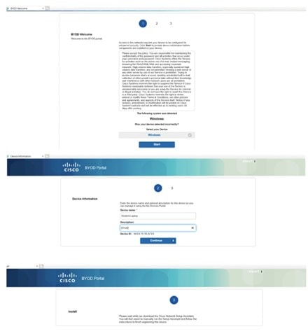
-
Posture Policy: Posture is a Cisco ISE service that allows you to check the compliance, also known as posture, of endpoints before allowing them to connect to your network. A posture agent, such as the Cisco ISE AnyConnect Posture Agent runs on the endpoint. The Client Provisioning service ensures that endpoints receive the appropriate posture agent.
After the endpoint is brought up to compliance and successfully onboarded, the portal notifies the user that they now have full access. Users can open their browser and navigate to other destinations, while Cisco ISE registers the end point as a BYOD device. The following figure shows the client provisioning workflow.
Figure 11. Client Provisioning Workflow 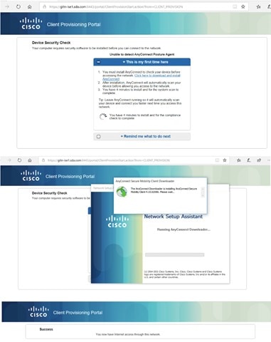
Guest Services with Multisite Remote Border
University campus administrators often need to manage extensive guest services across all their campus sites. Traditionally, guest users, which are bound to each individual fabric site, get IP addresses from the local site address pool and direct all traffic towards the local site borders. This setup adds complexity for address management and policy enforcement across multiple sites. To address this challenge, Cisco DNA Center provides the Multisite Remote Border solution using VN Anchors. This solution is also referred to as Multisite Remote Border. This solution allows traffic from a given VN at multiple dispersed sites to be aggregated back to a central location—an anchor site—using a single common subnet, rather than having to define and use per-site subnets for the guest VN. With a simplified and centralized common subnet structure, VN anchor sites significantly simplify the guest service deployments across sites and provide consistent and secure segmentation for guest traffic in university environments.
Using anchored services, traffic for the endpoints that belong to the anchored VN at each site are aggregated and tunneled back to the remote anchor border at the anchor site over a VXLAN. An anchor site functions very much like a traditional fabric site, but it forms a virtual fabric site serving a particular VN. This virtual fabric site has its own site border and control plane (CP) which are in the anchor site. What is special about the anchor site is that its edges and wireless controller are dispersed across multiple fabric sites (referred to as anchoring sites).
Multisite Remote Border is enabled on a per-VN basis. For an anchored VN, and ideally for guest services, all edges in the inherited sites use the anchor border and CP for data plane and control communication. Wireless controllers in the anchoring sites communicate with the anchor CP for wireless endpoint registration. For non-anchored traditional VNs, edges and wireless controllers still use their own site-local border and CP for data plane and control communication. Like other routing locators (RLOCs) of devices operating in a fabric role, the Loopback 0 address of the CP and anchor border node must be reachable via a /32 route in the global routing table on the edge nodes in the anchoring sites. Because the anchor border reachability may traverse multiple IP networks, the MTU must be considered along the entire path to accommodate the VXLAN’s 50-byte overhead.
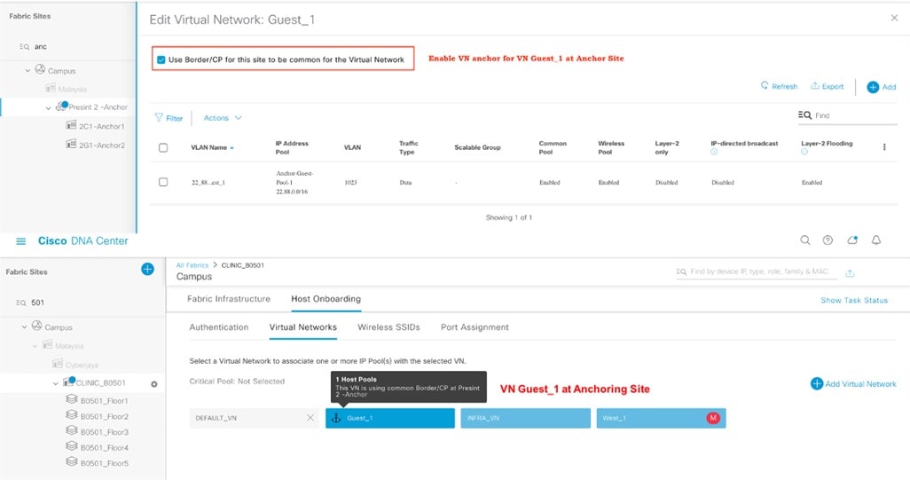
The guest VN is configured to use the anchor site. After a guest endpoint joins the guest SSID and passes the Central Web Authentication using Cisco ISE, it is associated with the anchored guest VN. Guest traffic is tunneled to the anchored border and egresses to the internet through a firewall. The following figure shows Multisite Remote Border enabled in the Cisco DNA Center GUI.
The following figure illustrates the traffic path of anchored guest traffic.
AI Endpoint Analytics
Universities need to manage many users and their devices. With BYOD, each student or faculty member has two to three devices per person. Along with scale comes the issue of security. Modern security threats seek vulnerable points of entry to exploit a network's valuable enterprise information. Identifying and tracking all the devices in a network is time-consuming and tedious. The Cisco AI Endpoint Analytics feature addresses this issue by identifying devices by type, manufacturer, model, OS type, communication protocols, and ports using passive network telemetry monitoring and deep packet inspection. It allows an administrator to create profiling rules to classify devices based on those attributes. Coupled with machine learning, Cisco DNA Center can detect spoofed endpoints and help administrators determine the appropriate action.
Cisco AI Endpoint Analytics is an additional application that runs with Cisco DNA Center. Download and install the application from the catalog server. Then, enable it in Cisco DNA Center System Settings. Cisco DNA Center needs to connect to the cloud to download the latest endpoint analytics model. After you successfully install Cisco AI Endpoint Analytics, you can access it from the Cisco DNA Center home page by clicking the menu icon and then Policy.
Cisco AI Endpoint Analytics uses multiple methods to detect malicious endpoints. It uses the Change in Profile Labels, NAT mode detection, concurrent MAC address, posture, authentication method, and machine learning features to identify and flag spurious endpoints. An overall trust score is generated for every endpoint. The trust score is a weighted average of multiple risk scores. A lower trust score indicates a higher risk for an endpoint.
Furthermore, Cisco DNA Center shares the endpoint classification attributes with Cisco ISE. When new devices onboard through identity-based authentication, they can be automatically identified by manufacturer and type and added to the appropriate group. Defining and enforcing security policies is easier when these policies are applied to groups rather than to individual endpoints. Group-based policy can easily be updated to adapt to new circumstances, such as security breaches by endpoints, and applied globally to the entire network.
For example, a printer in the library has been spoofed by a student’s laptop to gain access to the network.
The following figure shows the printer MAC address being flagged as malicious and other trust score details.
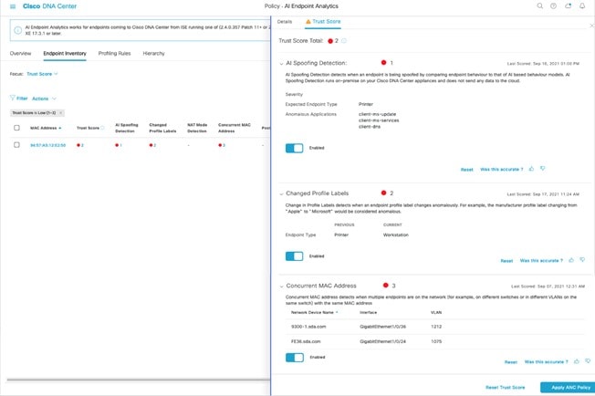
Cisco DNA Center can identify the occurrence of the printer MAC address at two places in the network, identifying the type of malicious device and also identifying the traffic type being sent by the compromised MAC address.
Layer 2 Guest Termination Outside the Fabric
Customers sometimes need to have Layer 2-level traffic inspection for guests who are using the network. This requirement means that the first hop for all guest traffic needs to be outside the fabric. This implementation is achieved using a combination of Cisco DNA Center and manual device configuration. While the guest traffic is VXLAN-encapsulated and passes through the fabric, the first hop or gateway for guest traffic is outside the fabric.
To achieve this configuration, the guest network/SSID is deployed from Cisco DNA Center. In addition, there is a Layer 2 handoff on the border for the fabric site for the guest VN. The firewall or Layer 2 termination point is at the other end of the Layer 2 handoff. The firewall is configured with the IP address in the same subnet as that of the guest. The DHCP server from which the guest gets its IP address must provide the Router IP as the firewall Layer 2 termination IP instead of the Fabric Anycast Gateway IP.
With these changes, the firewall IP acts like a client in the guest VN. When the guest laptop gets its IP address and wants to send traffic, the first hop (the Layer 2 termination point outside the fabric) is resolved via L2 LISP and the laptop can successfully communicate to the outside. With this configuration, further Layer 2 inspection for guest traffic can be achieved outside the fabric.
 Feedback