Solution Overview
This guide explains how to use Cisco DNA Center 2.3.5.5 to deploy and manage a legacy wireless local area network (WLAN) within an enterprise network, using Cisco Catalyst 9800 Series Wireless Controllers, Cisco IOS XE Cupertino 17.9.4a.
This guide provides technical guidance to design, deploy, and operate a Cisco WLAN using Cisco DNA Center.
This guide contains the following main sections:
-
Define the wireless network presents a high-level overview of the campus, remote office, and cloud-based WLAN that is designed and deployed through Cisco DNA Center.
-
Design the wireless network discusses the integration of Cisco DNA Center with Cisco Identity Services Engine (Cisco ISE); creation of the site hierarchy—including the importing of floor maps—within Cisco DNA Center; configuration of various network services necessary for network operations, such as AAA, DNS, DHCP, NTP, SNMP, and Syslog servers; and configuration of wireless settings, including WLANs/SSIDs, VLANs, and RF profiles for the WLAN deployment.
-
Deploy the wireless network discusses discovery of the wireless controllers, managing the software images running on the wireless controllers, configuring HA SSO redundancy on the wireless controllers, provisioning the enterprise and guest wireless controllers within Cisco DNA Center, joining APs to the enterprise wireless controller HA SSO pair, provisioning the APs within Cisco DNA Center, and positioning the APs on the floor maps within Cisco DNA Center.
-
Monitor and operate the wireless network discusses how to use Cisco DNA Assurance to monitor and troubleshoot the WLAN deployment.
The audience for this guide includes network design engineers and network operations personnel who want to use Cisco DNA Center to deploy a Cisco WLAN within their wireless networks.
Prerequisites
Before you can deploy and manage a legacy WLAN within an enterprise network, Cisco DNA Center must be installed and properly configured. For more information about installing and configuring Cisco DNA Center, see the Cisco DNA Center Installation Guide.
The following table displays the round-trip time (RTT) requirements between Cisco DNA Center and the specified network elements.
The latency between the Cisco DNA Center appliance and a managed device should be ~100 milliseconds RTT or less. After 100 milliseconds, longer execution times could be experienced for certain events, such as inventory collection, provisioning, and image update (SWIM). Cisco does not support an RTT of more than 300 milliseconds. For more details on RTT and supported scale, see the Cisco DNA Center Data Sheet.
| Source Device | Target Device | Maximum RTT Supported |
|---|---|---|
|
Cisco DNA Center Node |
Cisco DNA Center Node |
10 milliseconds |
|
Cisco DNA Center Node |
Cisco ISE |
300 milliseconds |
|
Cisco DNA Center Node |
Wireless Controller |
200 milliseconds |
|
Wireless Controller |
Access Points |
20 milliseconds (local mode) |
|
Wireless Controller |
Access Points |
300 milliseconds (flex mode) |
|
Wireless Controller |
Cisco ISE |
100 milliseconds |
| Wireless Controller Model | Maximum Number of APs | Maximum Number of Clients |
|---|---|---|
|
Catalyst 9800-L |
250 |
5000 |
|
Catalyst 9800-40 |
2000 |
32,000 |
|
Catalyst 9800-80 |
6000 |
64,000 |
|
Catalyst 9800-CL (4 CPU/8 GB RAM) |
1000 |
10,000 |
|
Catalyst 9800-CL (6 CPU/16 GB RAM) |
3000 |
32,000 |
|
Catalyst 9800-CL (10 CPU/32 GB RAM) |
6000 |
64,000 |
| SKU | DN-SW-APL | DN2-HW-APL | DN2-HW-APL-L | DN2-HW-APL-XL |
|---|---|---|---|---|
|
Legacy Devices (switch, router, wireless controller) |
1000 |
1000 |
2000 |
5000 |
|
Legacy Wireless Access Points |
4000 |
4000 |
6000 |
13,000 |
|
Wireless Sensors |
600 |
600 |
800 |
1600 |
|
Concurrent Endpoints |
25,000 |
25,000 |
40,000 |
100,000 |
|
Transient Endpoints (over a 14-day period) |
75,000 |
75,000 |
120,000 |
250,000 |
|
Ratio of Endpoints to Wired |
Any |
Any |
Any |
Any |
|
Ratio of Endpoints to Wireless |
Any |
Any |
Any |
Any |
|
Site Elements |
2500 |
2500 |
5000 |
10,000 |
|
Wireless Controller |
500 |
500 |
1000 |
2000 |
|
Ports |
48,000 |
48,000 |
192,000 |
768,000 |
|
API Rate Limit (APIs/minute) |
50 |
50 |
50 |
50 |
|
NetFlow (flows/second) |
30,000 |
30,000 |
48,000 |
120,000 |
|
Concurrent Software Image Updates |
100 |
100 |
100 |
100 |
| Description | Supported Scale |
|---|---|
|
Devices (switch, router, wireless controller) |
10,000 |
|
Wireless Access Points |
25,000 |
|
Concurrent Endpoints |
300,000 |
|
Transient Endpoints (over a 14-day period) |
750,000 |
|
NetFlow (flows/second) |
250,000 |
|
Number of Floors (per wireless controller) |
1000 |
Required Network Ports
Cisco DNA Center requires that specific ports are open for traffic flows to and from the appliance, whether you open them using firewall settings or a proxy gateway. For more information, see the "Required Network Ports" topic in the Cisco DNA Center Second-Generation Appliance Installation Guide.
Certificate Management for Cisco DNA Center
By default, Cisco DNA Center uses self-signed certificates, but you can use a certificate that is signed by your internal certificate authority during deployment. To replace the default certificate, see the "Manage Certificates" topic in the Cisco DNA Center Security Best Practices Guide.
Define the Wireless Network
This section presents a high-level overview of the campus, remote office, and cloud-based WLAN that is designed and deployed through Cisco DNA Center.
There are three scenarios that outline three types of typical, legacy wireless deployments. In the first scenario, a campus wireless deployment with APs in local mode uses wireless controllers in a high availability (HA) configuration; the wireless controllers are located in the same campus building. In the second scenario, a remote office wireless deployment with APs in flex mode uses wireless controllers in an N+1 configuration; the wireless controllers are located in the data center. In the third scenario, a wireless network for a corporate event uses a wireless controller that is hosted in a cloud environment, such as Amazon Web Services (AWS).
Campus Wireless Deployment
The campus wireless deployment uses a pair of Cisco Catalyst 9800-40 Wireless Controllers in a high availability (HA) SSO configuration. Located on multiple floors within multiple buildings of the campus, the wireless controller pair functions as the enterprise wireless controller for access points (APs) in local mode. Wireless guest access is provided through a separate Cisco Catalyst 9800-CL Wireless Controller, which functions as a traditional guest wireless controller and is anchored to the enterprise (foreign) wireless controller.
The design and deployment of the WLAN is fully automated, utilizing intent-based networking (IBN). Cisco DNA Center is designed for IBN and provides a level of abstraction from the device-level user interface.
 Note |
In the production environment, the guest anchor wireless controller is typically connected to a DMZ segment off of a firewall to separate guest wireless traffic from internal employee traffic. In such designs, the firewall policy must be configured to allow the necessary traffic between the enterprise foreign wireless controller and the guest anchor wireless controller. |
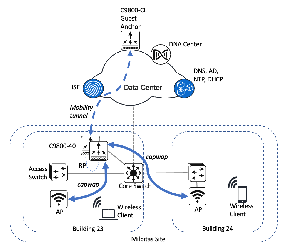
The campus wireless deployment includes the following features:
-
Site hierarchy consisting of a single area (Milpitas) and multiple buildings (Building 23 and Building 24), each with multiple floors (Floor 1 and Floor 2)
-
Legacy, centralized campus wireless deployment in which all wireless traffic is backhauled to the wireless controller
-
Enterprise SSID and guest SSID
-
A single pair of enterprise Catalyst 9800-40 Wireless Controllers in an HA SSO configuration
-
Guest wireless access through a dedicated guest Catalyst 9800-CL Wireless Controller, which is auto-anchored to the enterprise HA SSO wireless controller pair
Note |
The Cisco DNA Center CLI templates can be used to configure anything that cannot be configured through the intent-based profiles and/or the model config. This guide discusses the specific wireless controller features that can be configured in Cisco DNA Center. |
Wireless controllers must be assigned to sites during the Cisco DNA Center provisioning process. For this deployment guide, a Catalyst 9800-40 Wireless Controller HA SSO pair (C9800-40) will be assigned to Building 23 within the Milpitas area. There can only be one primary enterprise (nonguest) wireless controller for the APs on a floor at a given time, meaning that only one enterprise wireless controller can be provisioned per floor within Cisco DNA Center. The APs on Floor 1 and Floor 2 within Building 23 and the APs on Floor 1 within Building 24 will be provisioned to C9800-40 through Cisco DNA Center.
Remote Office Wireless Deployment
The remote office wireless deployment uses a pair of Cisco Catalyst 9800-40 Wireless Controllers in a high availability (HA) N+1 configuration. Located on multiple floors within a remote office building, the wireless controller pair functions as the enterprise wireless controller for access points (APs) in flex mode. Wireless guest access is locally switched, and employee (nonguest) wireless traffic is centrally switched. All authentication, whether for employee (WPA2/802.1X) or guest (WebAuth) wireless traffic, is centrally performed through Cisco ISE, highlighting the use of Cisco ISE as both a AAA server and a guest portal.
The design and deployment of the WLAN is fully automated, utilizing intent-based networking (IBN). Cisco DNA Center is designed for IBN and provides a level of abstraction from the device-level user interface.
Note |
Alternate designs for guest wireless traffic, including local termination with Direct Internet Access (DIA) at the remote office, may be implemented when combining WLAN functionality with Cisco SD-WAN. For more information, see Cisco SD-WAN: Enabling Direct Internet Access. |
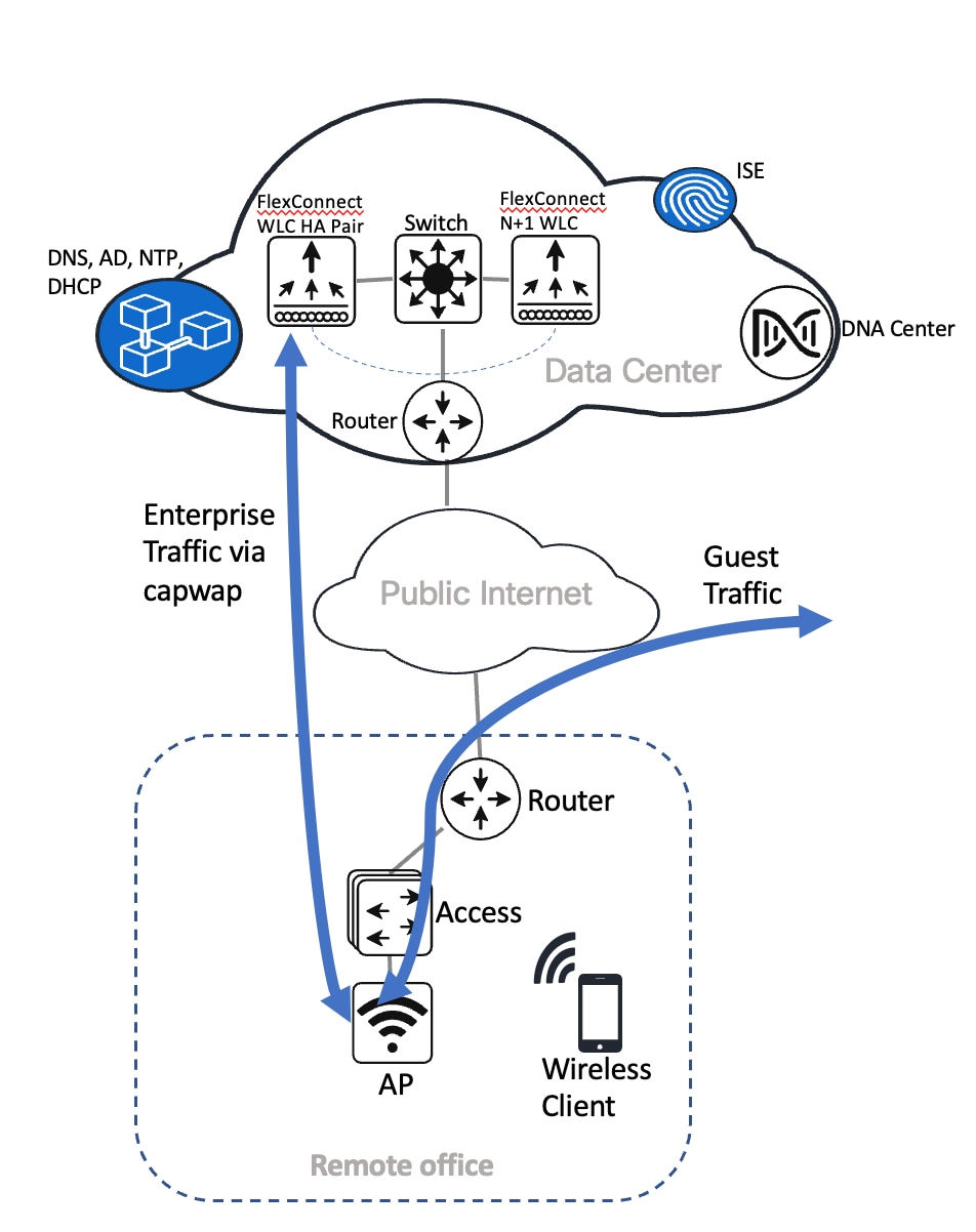
The remote office wireless deployment includes the following features:
-
Site hierarchy consisting of a single area (New York) and a single building (Branch 5) with multiple floors (Floor 1, Floor 2, and Floor 3)
-
Legacy, flex mode in which data traffic is centrally switched for the enterprise SSID and locally switched for the guest SSID
-
Enterprise SSID and guest SSID
-
A single pair of enterprise Catalyst 9800-40 Wireless Controllers in an HA N+1 configuration
Note |
The Cisco DNA Center CLI templates can be used to configure anything that cannot be configured through the intent-based profiles and/or the model config. |
The wireless controllers must be assigned to sites during the Cisco DNA Center provisioning process. For this deployment guide, a Catalyst 9800-40 Wireless Controller HA SSO pair (C9800-40) will be assigned to Branch 5 within the New York area, even though the pair is physically located in the data center. There can be only one primary enterprise (nonguest) wireless controller for the APs on a floor at a given time, meaning only one enterprise wireless controller can be provisioned per floor within Cisco DNA Center. The APs on Floor 1 and Floor 2 within Branch 5, New York will be provisioned to C9800-40 through Cisco DNA Center.
Wireless Controller Hosted on AWS Deployment
This wireless deployment uses a Cisco Catalyst 9800-CL Wireless Controller hosted on Amazon Web Services (AWS). Located on an event center floor, the wireless controller is configured as the enterprise wireless controller for access points (APs) in flex mode. All authentication, whether for employee (WPA2/802.1X) or guest (WebAuth) wireless traffic, is centrally performed through Cisco ISE and located in the data center.
Cisco DNA Center is designed for IBN and provides a level of abstraction from the device-level user interface.
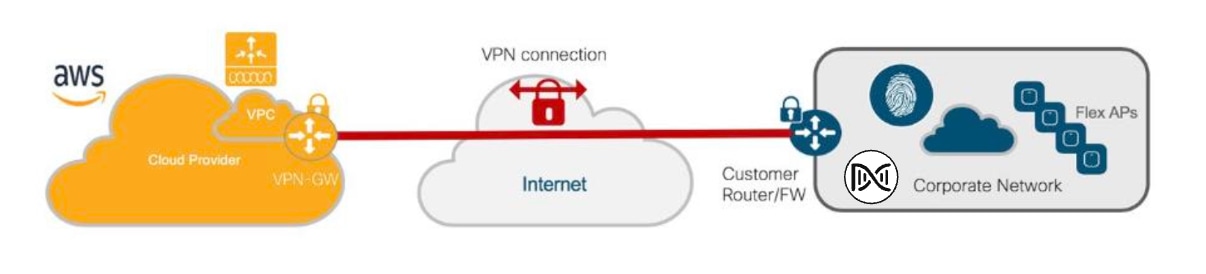
This wireless deployment includes the following features:
-
Site hierarchy consisting of a single area (San Jose) with an event center (Eventcenter) that has a single floor (Eventcenterfloor)
-
Legacy, flex wireless deployment where all wireless traffic is backhauled to the wireless controller
-
Flex mode in which data traffic is locally switched
-
Enterprise SSID and corporate special event SSID
-
A Catalyst 9800-CL Wireless Controller hosted on AWS
Note |
The Cisco DNA Center CLI templates can be used to configure anything that cannot be configured through the intent-based profiles and/or the model config. |
The wireless controllers must be assigned to sites during the Cisco DNA Center provisioning process. For this deployment guide, a Catalyst 9800 Wireless Controller (C9800-CL) on AWS will be assigned to Eventcenter within the San Jose area. There can be only one primary enterprise (nonguest) wireless controller for the APs on a floor at a given time, meaning only one enterprise wireless controller can be provisioned per floor within Cisco DNA Center. The APs on Eventcenterfloor within Eventcenter will be provisioned to C9800-CL on AWS through Cisco DNA Center.
Migration from the Legacy Network
This section provides an overview of the following migrations from the legacy network, using Cisco AireOS Wireless Controller or Cisco Prime Infrastructure:
-
Legacy Cisco AireOS Wireless Controller to Cisco Catalyst 9800 Series Wireless Controller
-
Cisco Prime Infrastructure to Cisco DNA Center
Migrate APs from a Legacy Cisco AireOS Wireless Controller to a Cisco Catalyst 9800 Series Wireless Controller
This section explains how to migrate access points (APs) from a legacy Cisco AireOS Wireless Controller to a Cisco Catalyst 9800 Series Wireless Controller. For this migration, the minimum AireOS version that is required is 8.5, with support for IRCM.
Procedure
|
Step 1 |
Add a temporary floor to the legacy site, which is managed by the Cisco AireOS Wireless Controller. |
||
|
Step 2 |
Discover the Catalyst 9800 Series Wireless Controller and provision the wireless controller to the legacy site that manages the newly added floor. |
||
|
Step 3 |
Enter the interface details, such as VLAN for legacy flow. |
||
|
Step 4 |
Configure a mobility tunnel between the Cisco AireOS Wireless Controller and the Catalyst 9800 Series Wireless Controller. |
||
|
Step 5 |
Migrate the APs to the Catalyst 9800 Series Wireless Controller using one of the following methods:
|
||
|
Step 6 |
(Optional) Remove the Cisco AireOS Wireless Controller from the inventory using the config cleanup option. |
Migrate from Cisco Prime Infrastructure to Cisco DNA Center
Before you begin
-
Using the Cisco Prime Infrastructure and Cisco DNA Center Compatibility Matrix, identify the Prime Data Migration Tool (PDMT) release that is compatible with your version of Cisco DNA Center.
-
Download the compatible PDMT release using the Cisco Software Download Tool.
Procedure
|
Step 1 |
Perform a readiness check using the Cisco Prime Infrastructure Cisco DNA Center Assessment and Readiness Tool (PDART). For more information about using PDART, see Use PDART - a Cisco DNA Center Readiness Tool. |
|
Step 2 |
Once you have assessed the readiness of the migration, use the PDMT to migrate your sites and devices from Cisco Prime Infrastructure to Cisco DNA Center. |
Design the Wireless Network
Ensure that the prerequisites are met, as described in Prerequisites.
This section contains the following topics and processes:
-
Integrate Cisco Identity Services Engine (ISE) with Cisco DNA Center
-
Cisco ISE and third-party AAA server
-
Configure the site hierarchy in Cisco DNA Center
-
Configure network services for network operation
-
Campus wireless deployment settings
-
Remote office wireless deployment settings
-
Design the Cisco Catalyst 9800-CL Wireless Controller hosted on AWS
Integrate Cisco ISE with Cisco DNA Center
The integration of Cisco Identity Services Engine (ISE) with Cisco DNA Center enables the sharing of information between the two platforms, including device and group information. Specific to this guide, the integration allows you to create a guest portal in Cisco ISE through a workflow in Cisco DNA Center. The guest portal is created when the guest wireless network is defined within a wireless profile in Cisco DNA Center. For more information, see Campus Wireless Deployment Settings.
Use the following procedures to integrate Cisco ISE with Cisco DNA Center:
-
Configure Cisco ISE as an authentication policy server
See Configure Cisco ISE as an Authentication and Policy Server to Cisco DNA Center.
-
Allow pxGrid connectivity from Cisco DNA Center into Cisco ISE
See the "Cisco pxGrid Cloud and Cisco ISE Integration" topic in the Cisco pxGrid Cloud Solution Guide.
Cisco ISE and Third-Party AAA Server
Even though Cisco DNA Center supports third-party AAA servers for RADIUS and TACACS+ authentications, Cisco ISE provides additional analytics for endpoints.
Configure Cisco ISE as an Authentication and Policy Server to Cisco DNA Center
Before you begin
Procedure
|
Step 1 |
Log in to the Cisco DNA Center web console using an IP address or a fully qualified domain name. Example: |
|||||||||||||||||||||||||||||||||||||||||||||||||||||||||||||||||||||||
|
Step 2 |
From the top-left corner, click the menu icon and choose . |
|||||||||||||||||||||||||||||||||||||||||||||||||||||||||||||||||||||||
|
Step 3 |
In the left pane, from the External Services drop-down list, choose Authentication and Policy Servers. |
|||||||||||||||||||||||||||||||||||||||||||||||||||||||||||||||||||||||
|
Step 4 |
From the Add drop-down list, choose ISE. The Add ISE server slide-in pane is displayed. |
|||||||||||||||||||||||||||||||||||||||||||||||||||||||||||||||||||||||
|
Step 5 |
Enter the server details in the required fields. The following table describes the fields in the Add ISE server slide-in pane.
For this design and deployment guide, the following information was entered.
|
|||||||||||||||||||||||||||||||||||||||||||||||||||||||||||||||||||||||
|
Step 6 |
Click Add to create the Cisco ISE server within Cisco DNA Center. The ISE server Integration slide-in pane displays a message about accepting the Cisco ISE certificate and establishing trust. 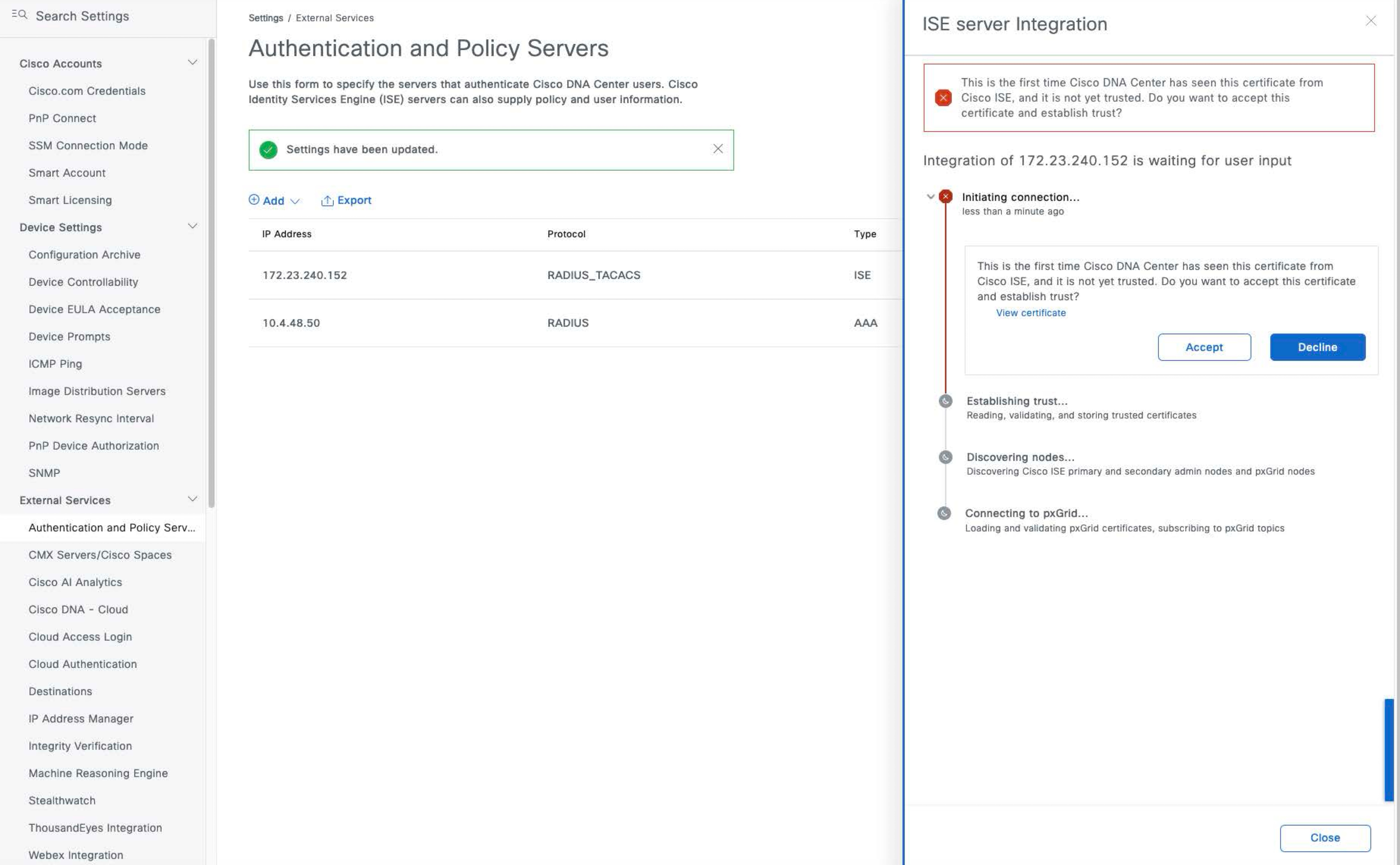
|
|||||||||||||||||||||||||||||||||||||||||||||||||||||||||||||||||||||||
|
Step 7 |
Click Accept. After the integration is complete, the Authentication and Policy Servers window is displayed. The new Cisco ISE server should display an ACTIVE status. If you want to change any server settings, hover your cursor over the ellipsis icon ( 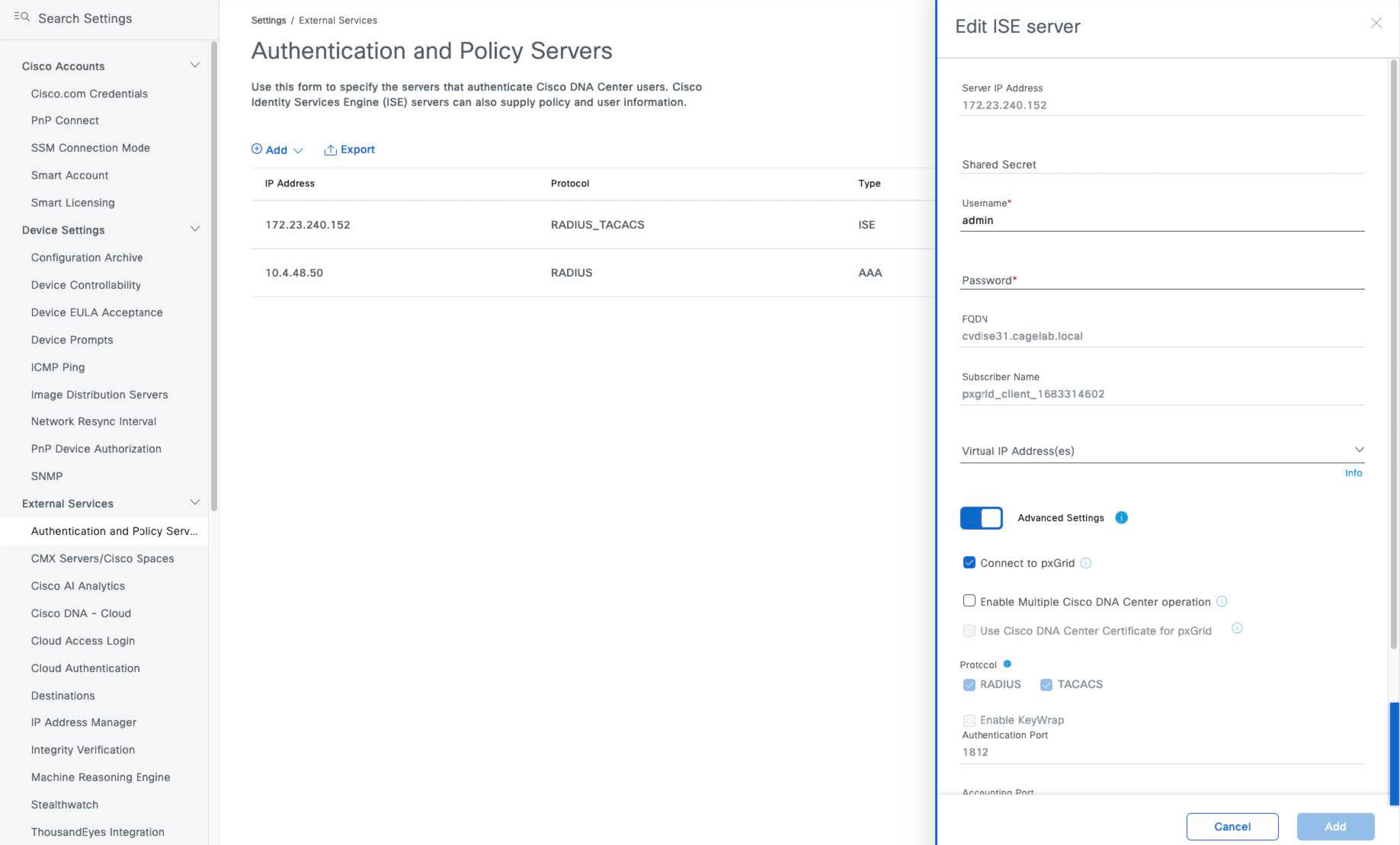
|
Configure Site Hierarchy and Import Floor Maps
The configuration of the site hierarchy includes defining the network sites for deployment and defining the hierarchical relationships of the network sites, which consist of areas, buildings, and floors. Child sites automatically inherit certain attributes from parent sites, but you can override the attributes within the child site.
The following table summarizes the site hierarchy for this guide. A single area (Milpitas) is provisioned, containing multiple buildings (Buildings 23 and Building 24) with multiple floors (Floor 1 and Floor 2).
| Name | Type of Site | Parent | Additional Information |
|---|---|---|---|
|
Milpitas |
Area |
Global |
— |
|
Building 23 |
Building |
Milpitas |
Address: 560 McCarthy Boulevard, Milpitas, California 95035 |
|
Building 24 |
Building |
Milpitas |
Address: 510 McCarthy Boulevard, Milpitas, California 95035 |
|
Floor 1 |
Floor |
Building 23 |
Dimensions: 200 ft. x 274 ft. x 10 ft. APs on this floor are provisioned to the Cisco Catalyst 9800 Series Wireless Controller HA pair. |
|
Floor 2 |
Floor |
Building 23 |
Dimensions: 200 ft. x 274 ft. x 10 ft. APs on this floor are provisioned to the Cisco Catalyst 9800 Series Wireless Controller HA pair. |
|
Floor 1 |
Floor |
Building 24 |
Dimensions: 200 ft. x 250 ft. x 10 ft. APs on this floor are provisioned to the Cisco Catalyst 9800 Series Wireless Controller HA pair. |
|
Floor 2 |
Floor |
Building 24 |
Dimensions: 200 ft. x 250 ft. x 10 ft. APs on this floor are provisioned to the Cisco Catalyst 9800 Series Wireless Controller HA pair. |
This section contains the following processes:
-
Create an area
-
Create a building within an area
-
Create a floor in a building
-
Create and position a planned AP by using the Cisco DNA Center GUI or by importing from Cisco Prime Infrastructure or Ekahau
Create an Area
Before you begin
To complete this action, your user profile must be assigned the SUPER-ADMIN-ROLE or the NETWORK-ADMIN-ROLE.
Procedure
|
Step 1 |
Login to the Cisco DNA Center web console using an IP address or a fully qualified domain name. Example: |
|
Step 2 |
From the top-left corner, click the menu icon and choose . The Network Hierarchy window is displayed. If this is the first time you have configured the network hierarchy, the left hierarchy pane may only display a single Global entry. 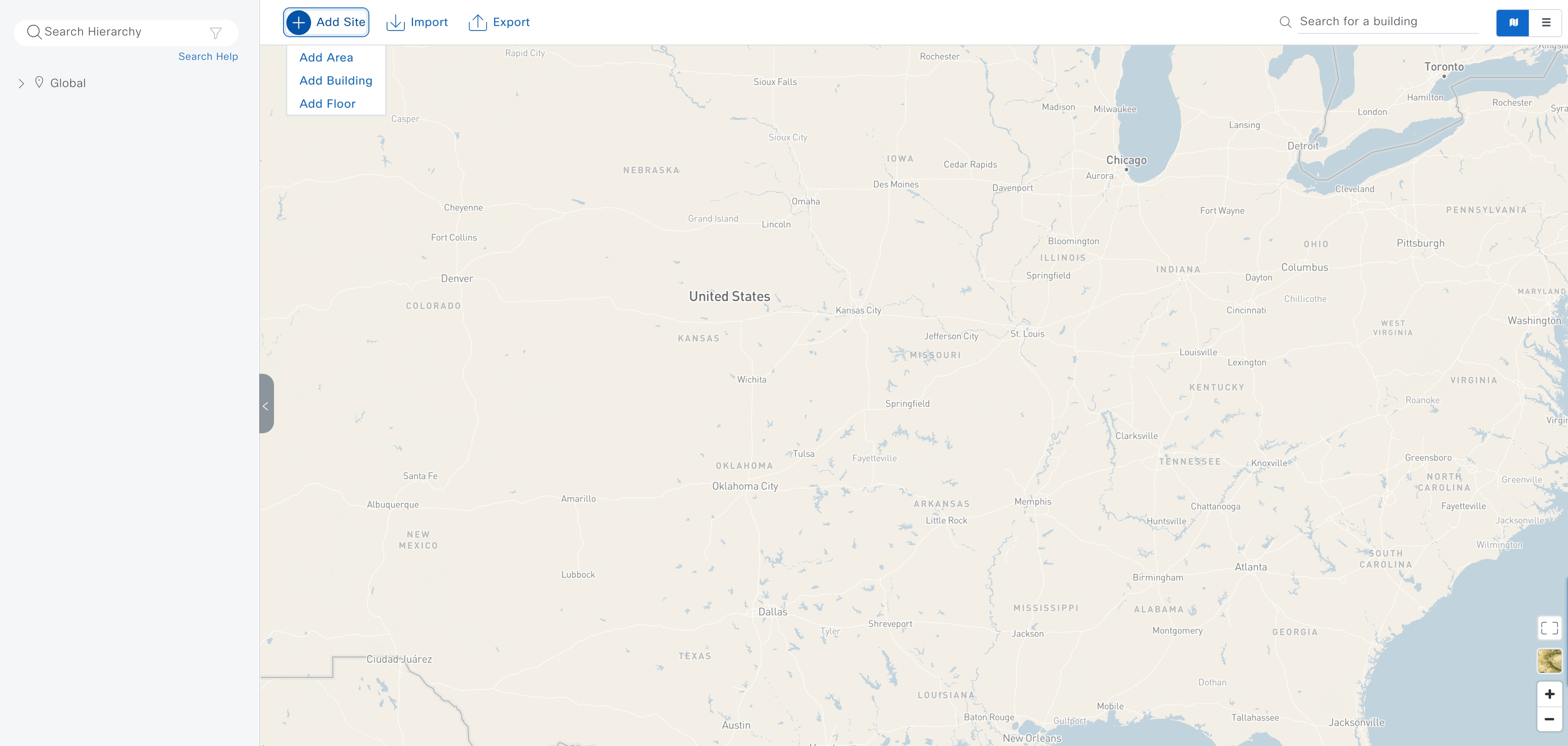 |
|
Step 3 |
Click . The Add Area dialog box is displayed. 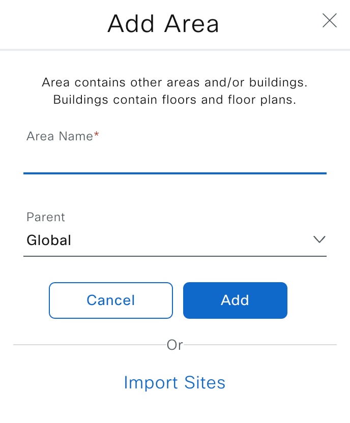 |
|
Step 4 |
In the Add Area dialog box, from the Parent drop-down list, enter the Area Name and choose the desired parent. For this deployment guide, choose Global for the Parent and create an area named Milpitas within an area named US. |
|
Step 5 |
Click Add. |
Create a Building Within an Area
Procedure
|
Step 1 |
From the top-left corner, click the menu icon and choose . |
|
Step 2 |
Click . The Add Building dialog box is displayed. 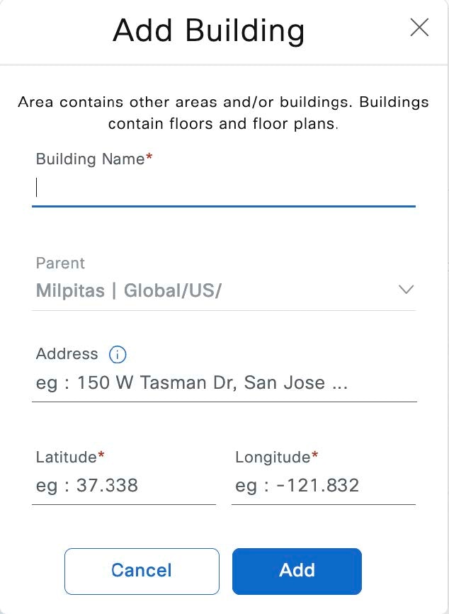 |
|
Step 3 |
In the Add Building dialog box, enter the Building Name and choose the desired area from the Parent drop-down list. For this deployment guide, enter Building 23 for the Building Name. For the Parent, choose Milpitas | Global/US. |
|
Step 4 |
Enter the building address or GPS coordinates using one of the following methods:
For this deployment guide, enter the address 560 McCarthy Boulevard, Milpitas, California 95035, which is configured for Building 23. |
|
Step 5 |
Click Add. For this deployment guide, repeat Step 1 through Step 5 to add a second building, Building 24, to the Milpitas area. |
Create a Floor in a Building
AP locations and wireless coverage (heatmaps) can be displayed from the floor maps. Floors are referenced during wireless provisioning.
Procedure
|
Step 1 |
From the top-left corner, click the menu icon and choose . |
||
|
Step 2 |
Click . The Add Floor dialog box is displayed. 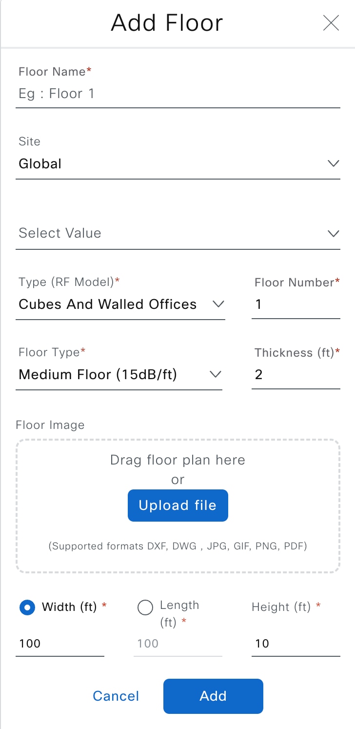
|
||
|
Step 3 |
In the Add Floor dialog box, enter the Floor Name and choose the desired area from the Site drop-down list. For this deployment guide, enter Floor 1 for the Floor Name. For the Site, choose Milpitas | Global/US, and for the Building, choose Building 23 | Global/US/Milpitas/. |
||
|
Step 4 |
Choose the appropriate space type from the Type (RF Model) drop-down list and enter the associated Floor Number. |
||
|
Step 5 |
Choose the appropriate floor type from the Floor Type drop-down list and enter the associated Thickness (ft). |
||
|
Step 6 |
Add the floor plan to the Floor Image area using one of the following methods:
|
||
|
Step 7 |
Click the Width (ft) radio button and enter the floor width in feet. |
||
|
Step 8 |
Click the Length (ft) radio button and enter the floor length in feet. |
||
|
Step 9 |
In the Height (ft) field, enter the ceiling height in feet.
For this deployment guide, enter 200 for the Width (ft). For the Length (ft), enter 275, and for the Height (ft), enter 10. |
||
|
Step 10 |
Click Add. For this deployment guide, repeat Step 1 through Step 10 three times to add Floor 2 to Building 23, Floor 1 to Building 24, and Floor 2 to Building 24. |
Create and Position a Planned AP in Cisco DNA Center
There are three ways to get a planned AP on a floor map:
-
Create a planned AP in Cisco DNA Center UI
-
Import a map that has been exported from Cisco Prime Infrastructure
-
Import a map that has been exported from Ekahau
Procedure
|
Step 1 |
From the top-left corner, click the menu icon and choose . |
|
Step 2 |
In the left hierarchy pane from the Global drop-down list, choose the desired floor for the AP. |
|
Step 3 |
Click Add/Edit. |
|
Step 4 |
From the Planned AP Models drop-down list, click Add model. 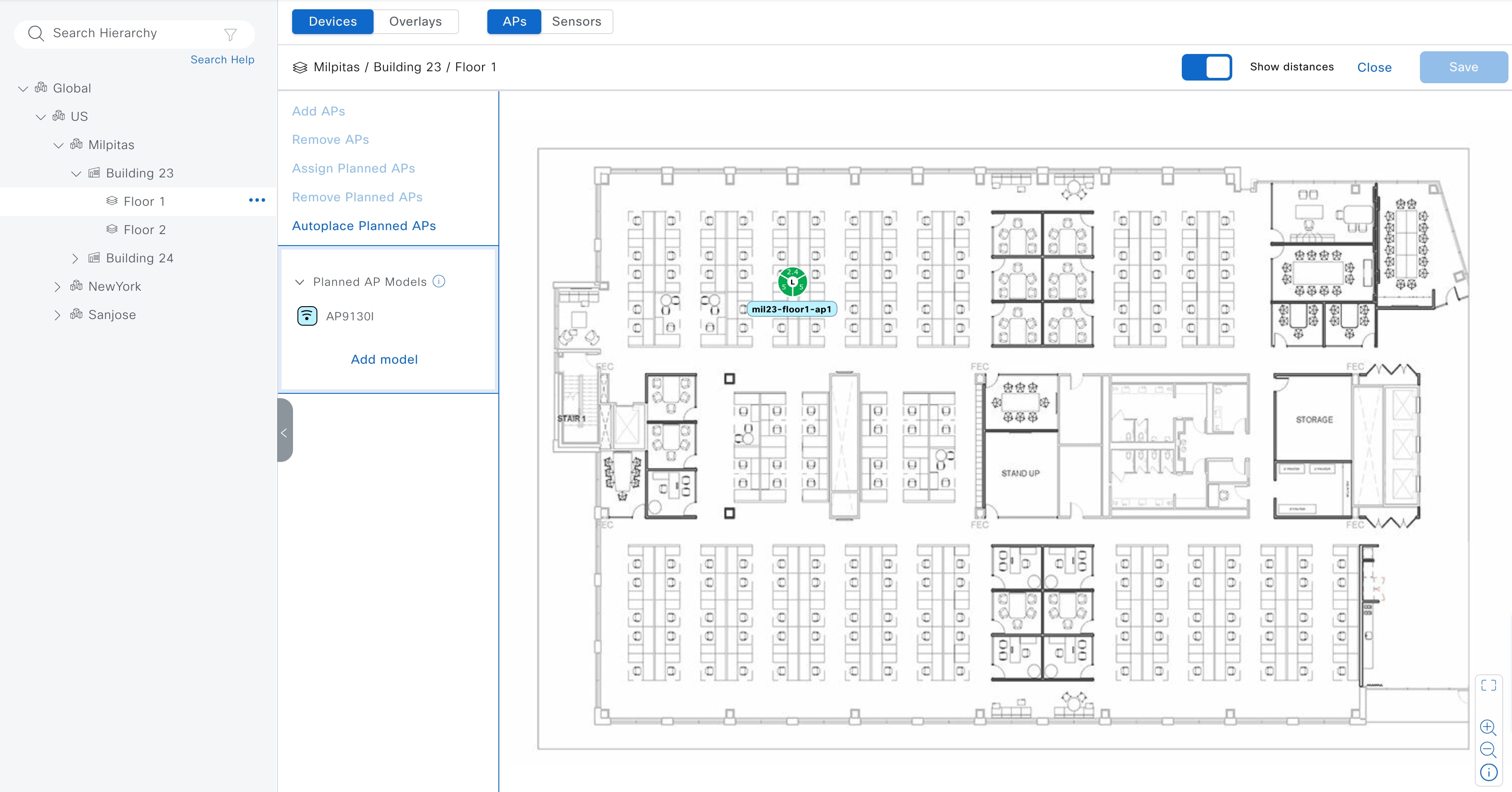
|
|
Step 5 |
In the Select AP models to add dialog box, choose the AP model from the drop-down list. |
|
Step 6 |
Click Add AP models. |
|
Step 7 |
From the Planned AP Models drop-down list, choose the desired AP model. |
|
Step 8 |
In the floor map, move your cursor to the desired location of the AP and click the location. |
|
Step 9 |
In the Edit Planned AP slide-in pane, ensure the Planned AP Name matches the real AP host name. If a red octagon with an X is displayed, choose an Antenna from the Antenna drop-down list. |
|
Step 10 |
Click Save. |
Import a Map from Cisco Prime Infrastructure
Before you begin
Procedure
|
Step 1 |
From the top-left corner, click the menu icon and choose . |
|
Step 2 |
In the left hierarchy pane, choose Global. Cisco Prime Infrastructure maps can be imported at the level. |
|
Step 3 |
Click . 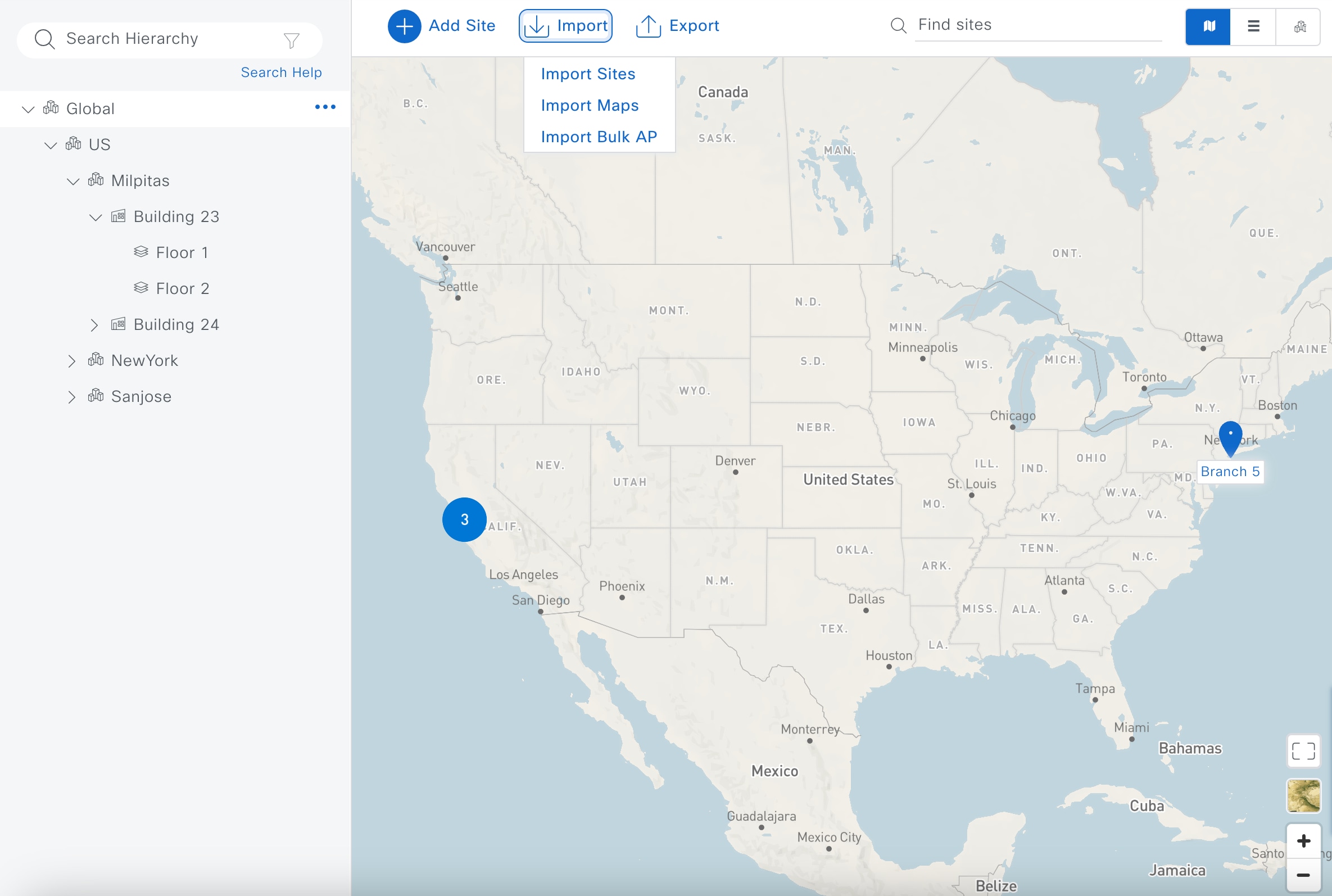
|
|
Step 4 |
In the Import Maps dialog box, import the map using one of the following methods:
|
|
Step 5 |
Click Import. |
Export a Map from Cisco DNA Center as an Ekahau Project File
To create and position a planned AP using Ekahau, first create the sites in Cisco DNA Center and export the sites as an Ekahau project. Then, create the planned AP in Ekahau and save the AP as an Ekahau project. Finally, import the Ekahau project back into Cisco DNA Center.
Note |
You can only export an Ekahau project file at a non-nested site level, which means there can be only one site with buildings within the chosen site. |
The following steps explain this process:
Procedure
|
Step 1 |
From the top-left corner, click the menu icon and choose . |
|
Step 2 |
In the left hierarchy pane, choose the appropriate site for your map. For this deployment guide, choose Milpitas. |
|
Step 3 |
Hover your cursor over the ellipsis icon ( 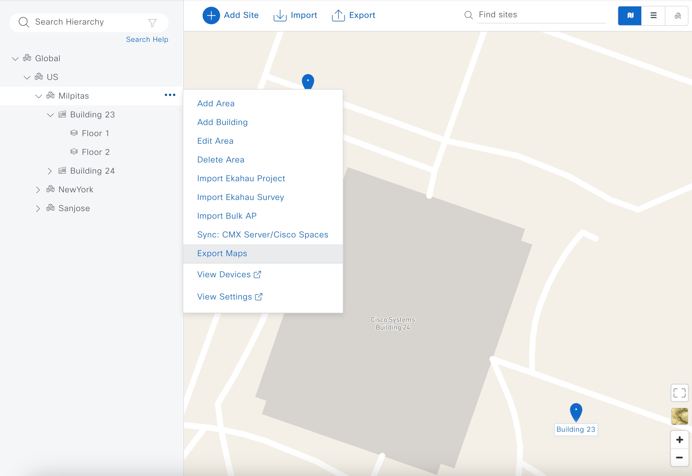
|
|
Step 4 |
In the Export Maps dialog box, enter the desired file name and click the Ekahau Project radio button. 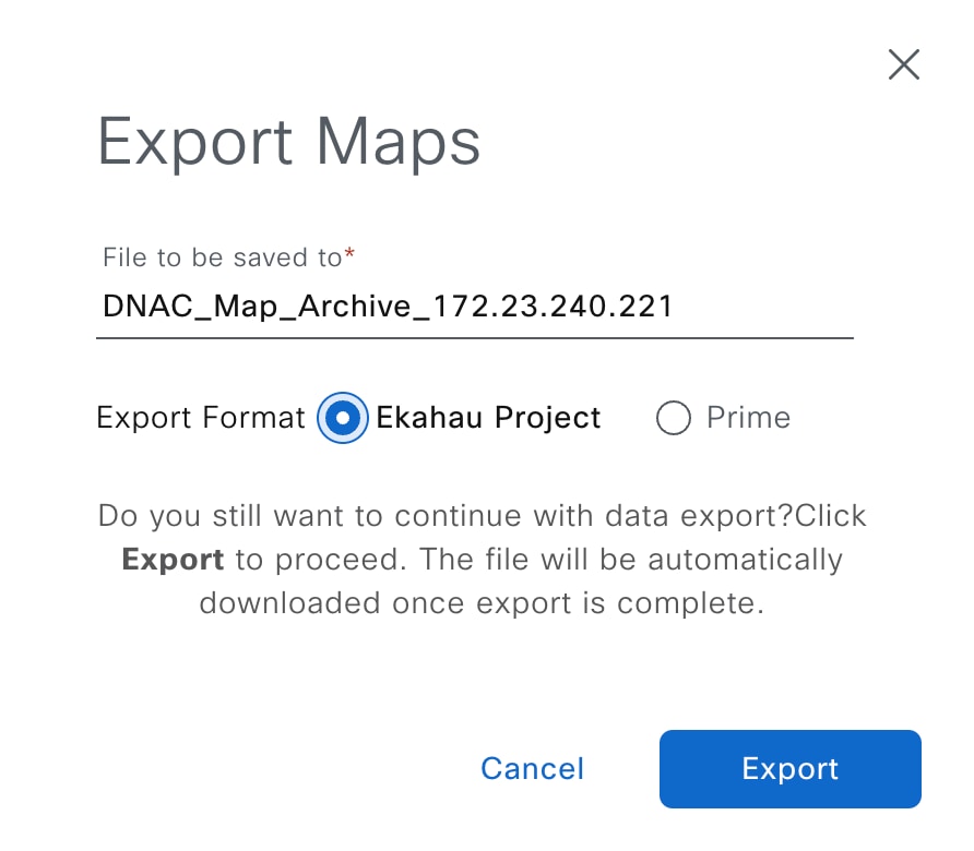
|
|
Step 5 |
Click Export. |
Import a Map from Ekahau
Before you begin
Procedure
|
Step 1 |
From the top-left corner, click the menu icon and choose . |
|
Step 2 |
In the left hierarchy pane, choose the appropriate site for your map. For this deployment guide, choose Milpitas. |
|
Step 3 |
Hover your cursor over the ellipsis icon ( 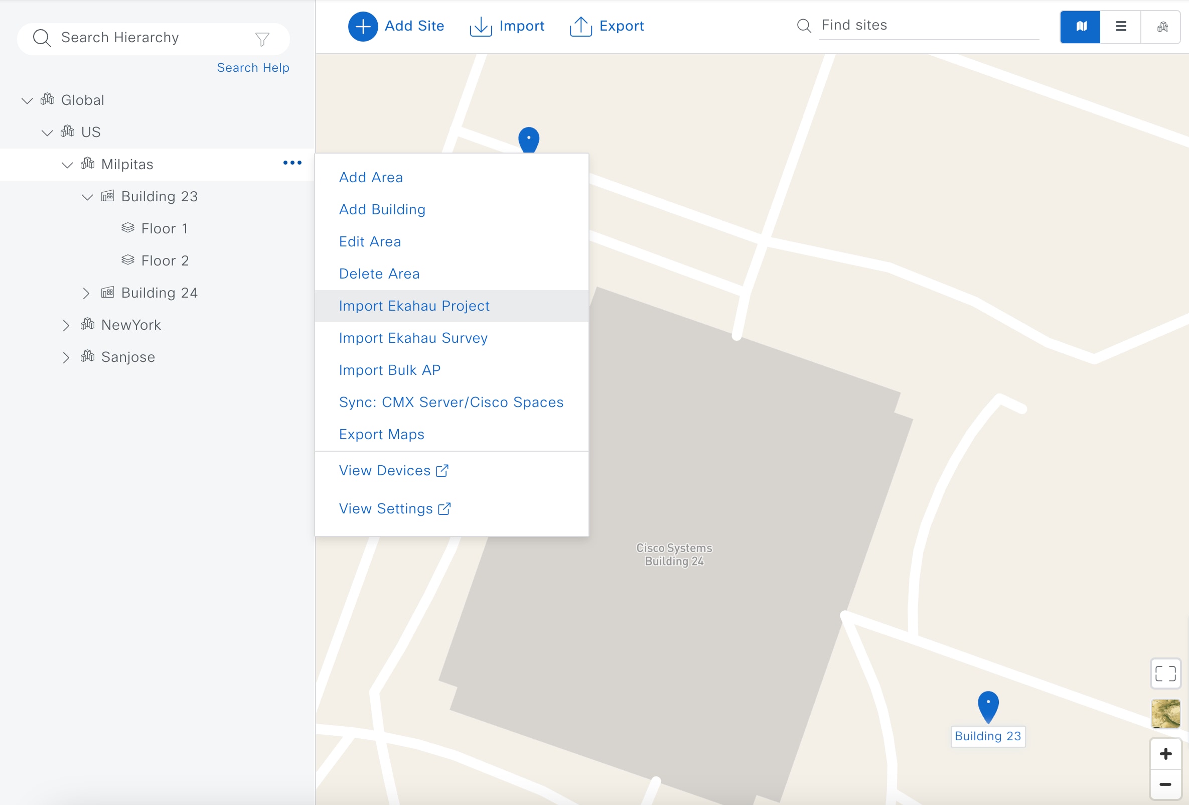
|
|
Step 4 |
In the Import Ekahau Project dialog box, import the map using one of the following methods:
|
|
Step 5 |
Click Import. |
Configure Network Services for Network Operation
This section explains how to configure AAA, DHCP, DNS, NTP, SNMP, and syslog services that align with the site hierarchy in Cisco DNA Center. If the services use the same servers across the entire site hierarchy, you can configure the services globally. The inheritance properties of the site hierarchy allow global settings to be available to all sites. Differences for individual sites can then be applied on a site-by-site basis. This guide shows the network services created globally.
Procedure
|
Step 1 |
From the top-left corner, click the menu icon and choose . |
||||||||||||||||||||||||||
|
Step 2 |
In the left hierarchy pane, choose Global. |
||||||||||||||||||||||||||
|
Step 3 |
Click + Add Servers. |
||||||||||||||||||||||||||
|
Step 4 |
In the Add Servers dialog box, check the AAA check box and the NTP check box. This guide does not require the deployment of Image Distribution or Stealthwatch Flow Destination, so do not check the Image Distribution check box or the Stealthwatch Flow Destination check box. |
||||||||||||||||||||||||||
|
Step 5 |
Click OK. An AAA server and an NTP server are now displayed in the Network window. |
||||||||||||||||||||||||||
|
Step 6 |
Configure the relevant fields for the AAA Server. For both network devices and wireless clients, this design and deployment guide uses Cisco ISE as the AAA server (which uses the RADIUS protocol). For this guide, the following fields were configured for the AAA Server.
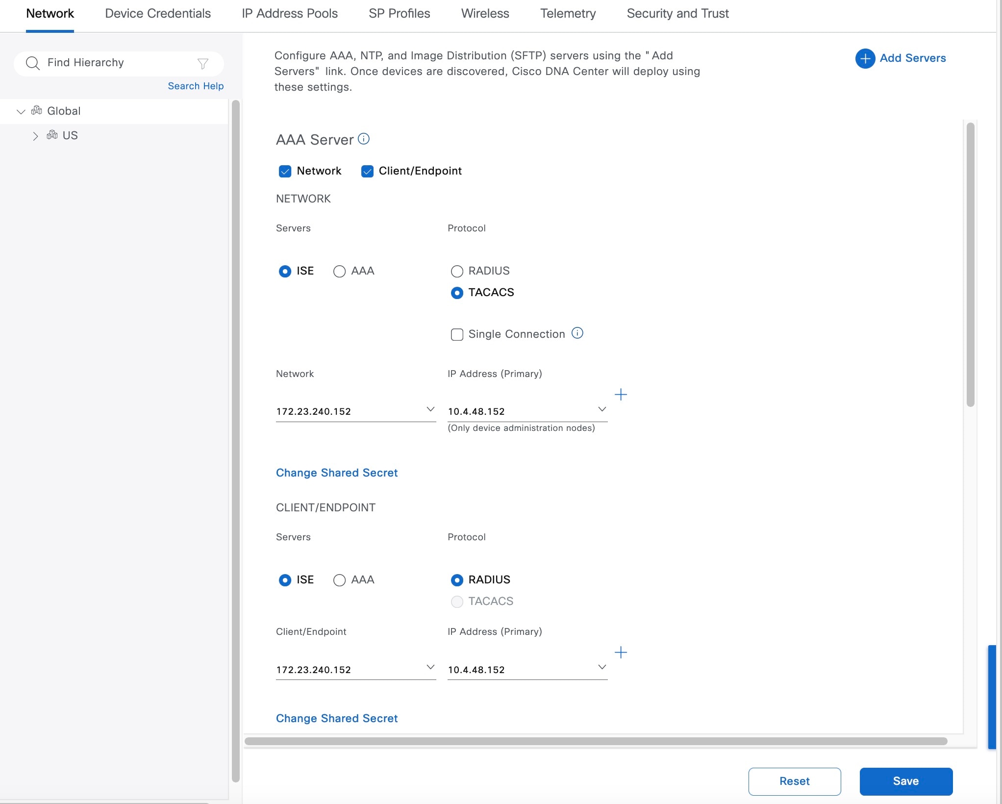
|
||||||||||||||||||||||||||
|
Step 7 |
Configure the relevant fields for the DHCP Server. This design and deployment guide uses a single Microsoft Active Directory (AD) server, which functions as both the DNS and DHCP servers for the network. For this guide, the following field was configured for the DHCP Server.
|
||||||||||||||||||||||||||
|
Step 8 |
Configure the relevant fields for the DNS Server. Because this design and deployment guide uses a lab network, the DNS Server configuration only used a single DNS domain. For this guide, the following fields were configured for the DNS Server.

|
||||||||||||||||||||||||||
|
Step 9 |
Configure the relevant fields for the NTP Server. For production networks, multiple NTP servers can be added for resiliency and accuracy. Time synchronization within a network is essential for any logging functions, as well as secure connectivity such as SSH. Because this design and deployment guide uses a lab network, the NTP Server configuration only used a single NTP server. For this guide, the following fields were configured for the NTP Server.
|
||||||||||||||||||||||||||
|
Step 10 |
Choose the desired time zone from the Time Zone drop-down list. Because this design and deployment guide uses a lab network, a single time zone is used for the site hierarchy. In a production network, each site within the site hierarchy would reflect the time zone of the location. |
||||||||||||||||||||||||||
|
Step 11 |
For the Message of the day, check the Do not overwrite the existing MOTD banner on the device check box or enter your desired message in the text box. The Message of the day field controls the message displayed when logging in to the network device. This setting is not applicable to this design and deployment guide, so for this guide, the check box was checked for Do not overwrite the existing MOTD banner on the device. |
||||||||||||||||||||||||||
|
Step 12 |
Click Save. |
||||||||||||||||||||||||||
|
Step 13 |
At the top of the window, click Telemetry. |
||||||||||||||||||||||||||
|
Step 14 |
From SNMP Traps, configure the SNMP trap server. This design and deployment guide uses Cisco DNA Center as the SNMP server. If you check the Use Cisco DNA Center as SNMP server check box, SNMP trap information will be sent to Cisco DNA Center for Cisco AI Network Analytics. For this guide, the following fields were configured for the SNMP server.
|
||||||||||||||||||||||||||
|
Step 15 |
From Syslogs, configure the syslog server. This design and deployment guide uses Cisco DNA Center as the syslog server. If you check the Use Cisco DNA Center as syslog server check box, syslog information will be sent to Cisco DNA Center for Cisco AI Network Analytics. For this guide, the following fields were configured for the syslog server.
|
||||||||||||||||||||||||||
|
Step 16 |
Click Save. |
Campus Wireless Deployment Settings
To configure the campus wireless deployment settings, you need to create the following in Cisco DNA Center:
-
Wireless interfaces: The Ethernet interfaces (VLANs) that are used for terminating wireless traffic.
-
Enterprise wireless networks: Consist of the nonguest WLANs/SSIDs for the deployment.
-
Guest wireless networks: Consist of the guest WLANs/SSIDs for the deployment.
-
Wireless radio frequency (RF) profiles: Includes the radio frequency profiles for the deployment.
-
Wireless sensor settings: Wireless sensors provide the ability to run diagnostic tests on the WLAN and perform packet captures. For information about wireless sensors, see Monitor and Operate the Wireless Network.
-
CMX servers: Integration with CMX servers allows the location of wireless clients to be displayed on floor maps. For information about integration with CMX servers, see Monitor and Operate the Wireless Network.
-
Native VLAN: The native VLAN configuration is specific to FlexConnect Access Point (AP) deployments.
Note
This deployment guide describes a wireless network with APs that operate in the centralized (local) mode.
Recommendations
When configuring the campus wireless deployment settings, consider the following recommendations:
-
Similar to any production deployment, you must place the APs in a VLAN that is different from the Wireless Management Interface (WMI). If you must configure the APs in the same VLAN as the WMI for staging or testing purposes, Cisco recommends that you limit the number of APs to less than 100.
-
For APs in local mode, the round-trip latency must not exceed 20 milliseconds between the access point and the controller.
-
Use PortFast on AP switch ports for APs in local mode, supporting only the central switched WLANs. To configure the switch port for PortFast, set the port to be connected as a host port, using the switch port host command or the PortFast command. This configuration allows for a faster AP join process. There is no risk of loops, as the local mode APs never directly bridge traffic between VLANs. You can set the port directly on access mode.
-
For APs in Flex mode and local switching, the switch port needs to be in trunk mode for most scenarios. In such cases, use spanning-tree portfast trunk on the switch port.
-
To optimize the TCP client traffic encapsulation in CAPWAP, Cisco recommends that you always enable the TCP Maximum Segment Size (MSS) feature, as it can reduce the overall amount of CAPWAP fragmentation, thereby improving the overall wireless network performance. You must adjust the MSS value depending on the traffic type and Maximum Transmission Unit (MTU) of the Cisco Wireless Controller-to-AP path.
-
In the Cisco Catalyst 9800 Series Wireless Controller, TCP MSS adjust is enabled by default, with a value of 1250 bytes, which is considered an acceptable value for most deployments. You can further optimize the value depending on your setup. You must configure directly on the wireless controller or via the Template Hub.
Configure Wireless Interfaces
In Cisco DNA Center, the enterprise and guest WLANs terminate on the Ethernet VLAN interfaces. For this design and deployment guide, the following table shows the wireless interfaces created for the enterprise and guest WLANs.
| Name | VLAN | Usage |
|---|---|---|
|
employee |
160 |
Employee voice and data VLAN |
|
guest-dmz |
125 |
Guest data VLAN |
|
flex |
180 |
Flex client VLAN |
Procedure
|
Step 1 |
Log in to Cisco DNA Center using the IP address or the fully qualified domain name of your instance. For example: https://<Cisco_DNA_Center_IPaddr_or_FQDN>. The credentials (user ID and password) you enter must have SUPER-ADMIN-ROLE or NETWORK-ADMIN-ROLE privileges. |
||
|
Step 2 |
From the top-left corner, click the menu icon and choose . The Wireless Network Settings dashboard is displayed. 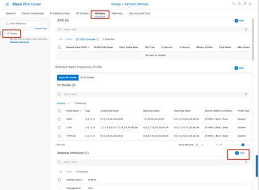
|
||
|
Step 3 |
Click Add next to Wireless Interfaces. The New Wireless Interface slide-in pane is displayed. 
|
||
|
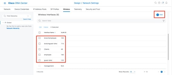
Step 4 |
Enter the Interface Name and VLAN ID for the wireless interface corresponding to the enterprise VLAN (employee), and then click Add. Repeat this procedure to add the wireless interface for the guest VLAN (guest-dmz). The two new wireless interfaces are displayed in the Wireless Network Settings dashboard. |
Configure Enterprise Wireless SSID
Enterprise wireless networks are the nonguest WLANs/SSIDs that are available for broadcast across the deployment, and you must define these wireless networks at the global level of the site hierarchy. Once defined, you can apply the enterprise wireless networks to wireless profiles, and then you can assign wireless profiles to one or more sites within the hierarchy.
Note |
Cisco recommends limiting the number of Service Set Identifiers (SSIDs) configured on the controller. You can configure 16 simultaneous WLANs/SSIDs (per radio on each AP). Each WLAN/SSID needs separate probe responses and beaconing transmitted at the lowest mandatory rate, and the RF pollution increases as more SSIDs are added. Some smaller wireless stations such as PDAs, Wi-Fi phones, and barcode scanners cannot cope with a high number of Basic SSIDs (BSSIDs) over the air, resulting in lockups, reloads, or association failures. Cisco recommends that you have one to three SSIDs for an enterprise and one SSID for high-density designs. By using the AAA override feature, you can reduce the number of WLANs/SSIDs while assigning individual per user VLAN/settings in a single SSID scenario. |
For this deployment guide, a single enterprise WLAN/SSID named lab3employee is provisioned.
Procedure
|
Step 1 |
From the top-left corner, click the menu icon and choose . |
||
|
Step 2 |
Click SSIDs. |
||
|
Step 3 |
Hover your cursor over + Add and choose Enterprise. The Basic Settings window is displayed. 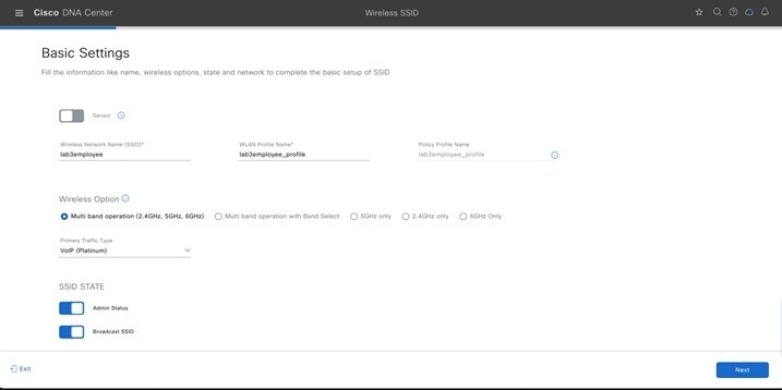
For information about features that can be configured for enterprise wireless networks via Cisco DNA Center, see Enterprise Wireless Network Features Configurable via Cisco DNA Center. |
||
|
Step 4 |
Enter the information for the Basic Settings and click Next. The next screen in the workflow is displayed. You can either attach the enterprise wireless network to an existing wireless profile, or you can create a new wireless profile and attach the enterprise wireless network.
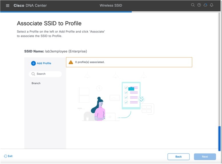
|
||
|
Step 5 |
Click + Add Profile to create and add a new wireless profile. The Create a Wireless Profile side panel is displayed. 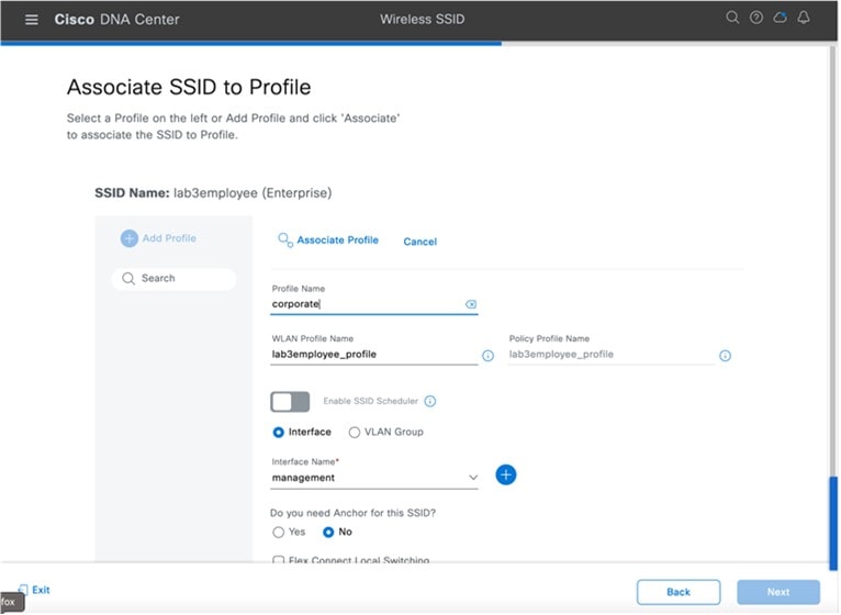
|
||
|
Step 6 |
In Profile Name, enter the name of the new wireless profile, and then click Associate Profile. For this deployment guide, create a wireless profile named Corporate. |
||
|
Step 7 |
Click the newly created profile and select the interface to be associated with this profile. |
||
|
Step 8 |
Click Save, and then click Next. |
||
|
Step 9 |
(Skip this step if SD-Access App is not deployed.) Under Fabric, select No. The Select Interface field is displayed. This deployment guide only discusses non-SDA wireless deployments using Cisco DNA Center. |
||
|
Step 10 |
From the Select Interface drop-down menu, select the employee to terminate the lab3Employee SSID onto the employee VLAN (VLAN 160) created in the previous procedure. |
||
|
Step 11 |
Under Guest Anchor option, choose No. |
||
|
Step 12 |
Uncheck the Flex Connect Local Switching check box, and then click Save to save an existing profile. If a profile does not already exist, create a new profile, and click Save. |
||
|
Step 13 |
Click Next. |
||
|
Step 14 |
Review the summary for the Network Profile, and click Save. |
||
|
Step 15 |
From the top-left corner, click the menu icon and choose . |
||
|
Step 16 |
In the Wireless Profiles table, from the Sites column, click Assign Site for your desired profile. For this deployment guide, click Assign Site for the newly created wireless profile, Corporate. |
||
|
Step 17 |
In the Global section, click > to display the Milpitas area. |
||
|
Step 18 |
Choose the Milpitas area. All of the child site locations are automatically selected: Building 23 with Floor 1, Floor 2, and Floor 3 and Building 24 with Floor 1, Floor 2, and Floor 3. |
||
|
Step 19 |
Click OK to close the site hierarchy side panel. |
||
|
Step 20 |
Click Edit under summary of Network Profiles Attach Template(s) to add CLI-based templates to the enterprise wireless network configuration.
|
||
|
Step 21 |
Click Save. The wireless profile named Corporate is assigned to the Milpitas area. The wireless profile contains the lab3employee SSID, so when wireless controllers and APs are assigned to the Milpitas area, the APs will broadcast the lab3employee SSID. |
||
|
Step 22 |
Click Finish to add the lab3employee enterprise wireless network. The new enterprise wireless network displays in the Wireless Network Settings dashboard. For information about configuring overrides, see Define Site Override Support. |
Enterprise Wireless Network Features Configurable via Cisco DNA Center
| Feature | Type | Description | ||||||||
|---|---|---|---|---|---|---|---|---|---|---|
|
Wireless Network Name (SSID) |
Text Field |
The SSID for the WLAN. |
||||||||
|
WLAN Profile Name |
Text Field |
Cisco DNA Center considers SSID_Profile to be the default, which is based on the SSID name. You can change the WLAN profile name as per your requirements. |
||||||||
|
Policy Profile Name |
Non Editable |
Policy Profile Name is the same as the WLAN Profile Name and is not editable. Based on the WLAN profile name, Cisco DNA Center automatically generates the policy profile name for the Cisco Catalyst 9800 Series Wireless Controller. |
||||||||
|
BROADCAST SSID |
On/Off Toggle |
Determines whether the SSID will be broadcast in wireless beacons and probe responses. |
||||||||
|
SSID STATE |
On/Off Toggle |
Use the toggle button to turn on or turn off the radios on the APs. When the Admin Status is disabled, the APs remain associated with the wireless controller and are accessible, but the APs still require licenses. |
||||||||
|
Sensor |
On/Off Toggle |
Ensure that Sensor is disabled. |
||||||||
|
WIRELESS OPTION |
Radio Button |
Determines in which RF bands the SSID will be broadcast. The following wireless options are available:
|
||||||||
|
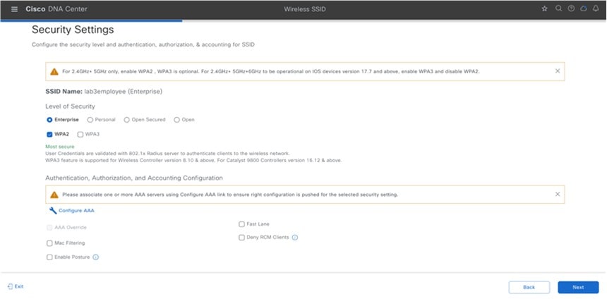
LEVEL OF SECURITY |
Radio Button |
Determines the Layer 2 (L2) security settings for the WLAN. Choose the encryption and authentication type for the network. The sites, buildings, and floors inherit settings from the global hierarchy. You can override the level of security at the site, building, or floor level. The following choices are available:
|
||||||||
|
Primary Traffic Type |
Drop Box |
For Catalyst 9800 Series Wireless Controllers, the setting applies a precious metals QoS SSID policy in both the upstream and downstream direction for the WLAN/SSID. Precious metals policies control the maximum DSCP marking within the CAPWAP header as traffic is tunneled between the AP and the Cisco Wireless Controller in centralized (local mode) designs. The following choices are available:
|
||||||||
|
Fastlane |
Check Box |
You can check this check box only when the type of Enterprise Network is Voice and Data. For the Catalyst 9800 Series Wireless Controller, the Fastlane check box enables Auto QoS in Fastlane mode. Auto QoS in Fastlane mode configures the Fastlane EDCA profile for both the 5 GHz and 2.4 GHz bands. However, no precious metals QoS SSID policy is applied to the WLAN/SSID when the Fastlane check box is selected. |
||||||||
|
Configure AAA |
Link |
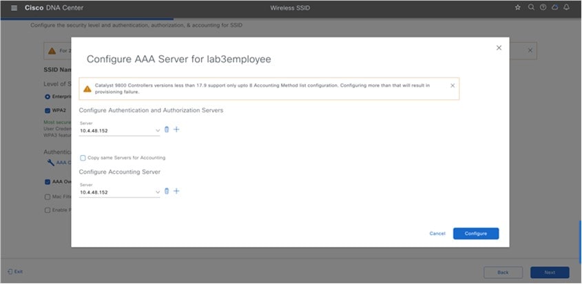
Click Configure AAA to add and configure the AAA servers for the enterprise wireless network SSID. Select the Authentication, Authorization, and Accounting server from Drop Box. Click + to add a server.
From the Additional Server drop-down list, choose the server IP address. To use the AAA server for accounting, check the Copy Same Servers for Accounting check box. To configure a different accounting server for an SSID, do the following:
Cisco DNA Center allows you to override the set of AAA server configurations for the SSID at the site level. For each set of overridden AAA settings per SSID, Cisco DNA Center creates a new WLAN profile with the corresponding AAA servers mapped to it. If an SSID is overridden for different floors, and you make changes in the AAA servers, Cisco DNA Center creates the new WLAN profiles equal to the number of floors. You must reprovision the device to override the AAA servers at the site level. |
||||||||
|
Deny RCM Clients |
Check Box |
Check the check box to deny clients with randomized MAC addresses. |
||||||||
|
Mac Filtering |
Check Box |
This is an additional L2 security settings that applies MAC address filtering for the WLAN. |
||||||||
|
AAA Override |
Check Box |
Check box to enable the AAA override functionality. By default, this check box is dimmed. You must configure an AAA server using the Configure AAA option to use this check box. |
||||||||
|
Enable Posture |
Check Box |
Check this check box to enable posture assessment. The Pre-Auth ACL List Name drop-down list appears when you enable posture. Posture is a service in Cisco Identity Services Engine (Cisco ISE) that allows you to check the state, also known as posture, of all the endpoints that are connecting to a network for compliance with corporate security policies. This allows you to control clients' access to protected areas of a network. |
||||||||
|
Pre-Auth ACL List Name |
Drop Box |
Choose the ACL list name that you already created to map with the SSID.
|
||||||||
|
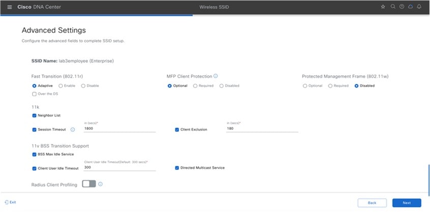
Advanced Settings – FAST TRANSITION (802.11r) |
Radio Button and Check Box |
Additional L2 security settings for the WLAN that controls 802.11r Fast Transition (FT). The following radio button choices are available:
Over the DS: Check box that enables Over-the-DS (Distribution System) Fast Transition. With Over-the-DS Fast Transition, the wireless station communicates with the target AP through the current AP, which is then forwarded through the wireless controller. The Cisco-Apple best practice is to disable Over-the-DS, even though the default is enabled. |
||||||||
|
Advanced Settings – Protected Management Frame (802.11w) |
Radio Button |
The options available under Protected Management Frame (802.11w) vary based on the settings that you chose under Level of Security. The following options may be available:
The Required option is mandatory for WPA3. |
||||||||
|
Advanced Settings – Session timeout |
Check Box and Integer Field |
Configures the maximum time for a client session to remain active before requiring reauthorization. The range is between 300 and 86,400 seconds (5 minutes and 24 hours). The default is enabled with a time of 1800 seconds (30 minutes). |
||||||||
|
Advanced Settings – Client Exclusion |
Check Box and Integer Field |
Configures the amount of time a wireless client is excluded from attempting to authenticate after the maximum number of authentication failures has been exceeded. The default is enabled with a time of 180 seconds (3 minutes). |
||||||||
|
Advanced Settings – MFP CLIENT PROTECTION |
Radio Button |
Additional security setting that controls the use of 802.11w Protected Management Frames for the WLAN. The following radio button choices are available:
|
||||||||
|
Advanced Settings – 11k Neighbor List |
Check Box |
Controls the use of 802.11k Assisted Roaming neighbor lists for the WLAN, which can limit the need for passive and active scanning by the wireless client. The default setting is enabled for the band (5 GHz or 2.4 GHz) with which the client is associated. |
||||||||
|
Advanced Settings – Client User Idle Timeout |
Check box |
Client User Idle Timeout: Check this check box to set the user idle timeout for a WLAN.
|
||||||||
|
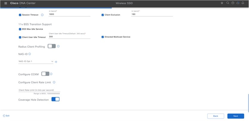
NAS-ID |
Drop-down list |
NAS-ID Opt drop-down list, choose the required type of network access server identifier (NAS ID). To specify a custom script for the NAS ID, choose Custom Option from the NAS-ID Opt drop-down list and enter the custom script in the corresponding Custom Script for Opt field. You can enter up to 31 alphanumeric characters, special characters, and spaces for the custom script. Cisco DNA Center does not support the special characters ?, ", < , and trailing spaces for the custom script.
(Optional) Click + to add another NAS ID. You can add up to three NAS IDs. |
||||||||
|
Advanced Settings – Coverage Hole Detection |
Toggle button |
Use the Coverage Hole Detection toggle button to enable or disable the coverage hole detection functionality. |
||||||||
|
Advanced Settings – Client Rate Limit |
Integer Field |
Configure Client Rate Limit: Enter a value for the client rate limit in bits per second. The valid range is from 8000 through 100,000,000,000. The value must be a multiple of 500. The following are the valid ranges for client rate limit on Cisco IOS XE devices:
|
||||||||
|
Advanced Settings – Directed Multicast Service |
Check box |
Directed Multicast Service: Check this check box to enable directed multicast service.
|
||||||||
|
Advanced Settings – Radius Client Profiling |
Toggle button |
For RADIUS Client Profiling, use this toggle button to enable or disable RADIUS profiling on a WLAN.
|
||||||||
|
Advanced Settings – CCKM |
Toggle button |
Configure CCKM: Use this toggle button to enable CCKM as the authentication key management option in Cisco DNA Center. Timestamp Tolerance: This field is visible only if you enable CCKM. Enter the CCKM tolerance level.
|
||||||||
|
Advanced Settings – 11v BSS TRANSITION SUPPORT |
Multiple Check Boxes and Integer Field |
Additional settings for support of 802.11v Wireless Network Management (WNM) for the WLAN. The following settings are available: BSS Max Idle Service: Check box that enables the maximum idle service for the WLAN. Allows APs to send the timeout value to the wireless client within association and reassociation response frames. The default setting is enabled. |
Enterprise Wireless Network Settings Configured in the Deployment Guide
| Feature | Settings |
|---|---|
|
Wireless Network Name (SSID) |
lab3employee |
|
Broadcast SSID |
On |
|
Admin Status |
On |
|
Wireless Option |
Multi band operation (2.4 GHz, 5 GHz, 6 GHz) |
|
Primary Traffic Type |
VoIP (platinum) |
|
Configure AAA |
AAA configured |
|
Level of Security |
WPA2 |
|
AAA Override |
Enabled |
|
Enable Posture |
Unchecked |
|
Deny RCM Clients |
Unchecked |
|
Advanced Security Options - Mac Filtering |
Unchecked |
|
Advanced Security Options - Fast Transition |
Adaptive |
|
Type of Enterprise Network |
Voice and Data |
|
Fastlane |
Unchecked |
|
Advanced Settings – FAST TRANSITION (802.11r) |
Adaptive, Over the DS Checked |
|
Advanced Settings – Mac Filtering |
Checked |
|
Advanced Settings – Session timeout |
Checked, 1800 seconds |
|
Advanced Settings – Client Exclusion |
Checked, 180 seconds |
|
Advanced Settings – MFP CLIENT PROTECTION |
Optional |
|
Advanced Settings –Protected Management Frame |
Disabled |
|
Advanced Settings – 11k Neighbor List |
Checked |
|
Advanced Settings – Radius Client Profiling |
Unchecked |
|
Advanced Settings – Configure Client Rate Limit |
Blank |
|
Advanced Settings – Coverage Hole Detection |
Checked |
|
Configure CCKM |
Unchecked |
|
NAS-ID |
Blank |
|
Advanced Settings – 11v BSS TRANSITION SUPPORT |
BSS Max Idle Service – Checked Client Idle User Timeout – Checked, 300 seconds Directed Multicast Service - Checked |
Define Site Override Support
WLAN profiles created with different AAA settings can be assigned at different site levels. Site level overrides will push a new WLAN profile to the wireless controller. You can override the global SSID with the settings based on area, buildings and floor levels. Perform the following procedure to configure the overrides.
Procedure
|
Step 1 |
From the top-left corner, click the menu icon and choose . |
||
|
Step 2 |
Click SSIDs. |
||
|
Step 3 |
Expand the sites, and then click on the desired site in the left pane. |
||
|
Step 4 |
Select lab3employee SSID, and then click Edit. 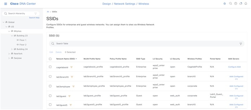
|
||
|
Step 5 |
Click Next and configure the override settings for the selected site. 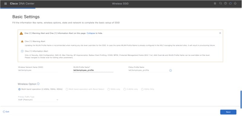
|
||
|
Step 6 |
Click Save in the last page to assign the profile to the site. The next time the wireless controller is provisioned, the configuration will be pushed to the wireless controller managing that site.
|
Configure Guest Wireless SSID
Guest wireless networks must be defined at the global level of the site hierarchy. Once defined, you can apply guest wireless networks to wireless profiles. You can then assign wireless profiles to one or more sites within the hierarchy.
For this deployment guide, a single guest wireless network (SSID) named lab3guest is provisioned.
Procedure
|
Step 1 |
From the top-left corner, click the menu icon and choose . |
||
|
Step 2 |
Click SSIDs. |
||
|
Step 3 |
Hover your cursor over + Add and choose Guest. The Basic Settings window is displayed. 
For information about the features that can be configured for guest wireless networks via Cisco DNA Center, see Guest Wireless Network Features Configurable via Cisco DNA Center. |
||
|
Step 4 |
Enter the information for the Basic Settings and click Next. The next screen in the workflow is displayed. Here, you can attach the guest wireless network to the existing corporate wireless profile. For information about the settings for the guest wireless network configured for this deployment guide, see Guest Wireless Network Settings Configured in the Deployment Guide. 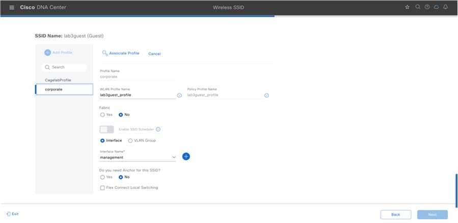
|
||
|
Step 5 |
Choose the Corporate Wireless profile. |
||
|
Step 6 |
Click Edit in the Wireless Profile side panel to add the guest wireless network. 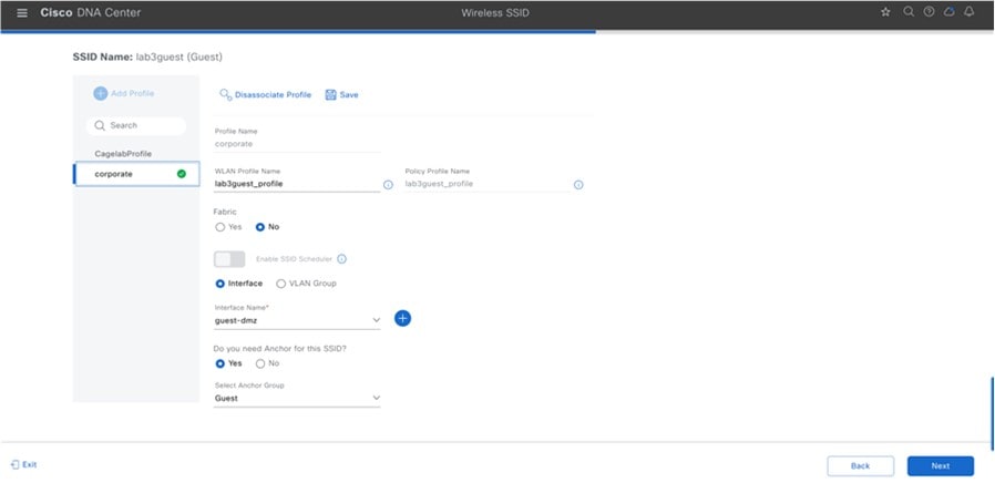
|
||
|
Step 7 |
Under Fabric, choose No. Selecting No will automatically cause additional fields to appear. This deployment guide only discusses non-SDA wireless deployments using Cisco DNA Center. |
||
|
Step 8 |
Select Yes next to Do you need a Guest Anchor for this Guest SSID. This will configure a traditional autoanchor relationship between the enterprise (foreign) and the guest (anchor) wireless controller. Typically, the guest (anchor) wireless controller is located within an Internet Edge DMZ segment of the campus network. If you choose Yes, from the Select Anchor Group drop-down list, choose an anchor group for the SSID. To create an anchor group, do the following: |
||
|
Step 9 |
From the Select Interface drop-down menu, select guest-dmz. This will terminate guest traffic on the guest-dmz VLAN (VLAN 125). |
||
|
Step 10 |
Click Next. The Portal Customization page is displayed. 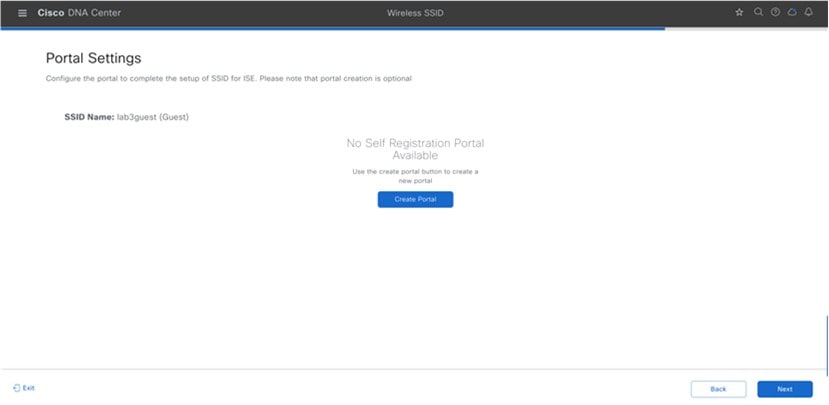
|
||
|
Step 11 |
To add a new guest portal within Cisco ISE, click Create Portal. The Portal Builder page is displayed. You have the option to leave without portal creation. 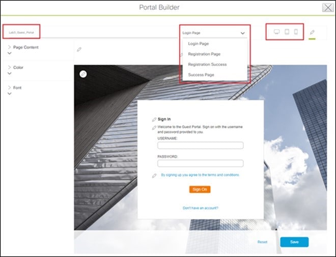
|
||
|
Step 12 |
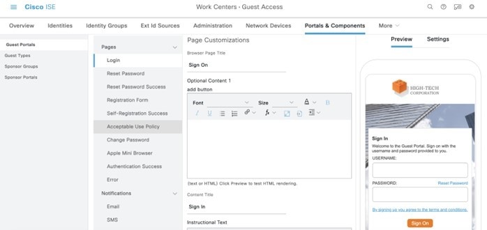
Enter the necessary information. You must at least name the guest portal. For this deployment guide, the portal has been named Lab3_Guest_Portal. The drop-down menu in the top center of the Portal Builder allows you to customize the Login Page, Registration Page, Registration Success, and Success Page of the portal. You can customize the color scheme, fonts, page content, logo, and background for the web portal. You can also preview the portal to see what it will look like on a smart phone, tablet, and computer. |
||
|
Step 13 |
Click Save to create the new guest portal on the Cisco ISE server and return to the guest wireless network workflow. The new guest portal is now displayed. |
||
|
Step 14 |
Click Next. The Summary page of Guest SSID Configuration is displayed. |
||
|
Step 15 |
Click Save. The guest wireless SSID (lab3guest) is displayed in the Wireless Network Settings dashboard. |
||
|
Step 16 |
Click Sites in network profile summary page to bring up a panel displaying the site hierarchy. |
||
|
Step 17 |
Under Global, click the >to display the Milpitas area. |
||
|
Step 18 |
Select the Milpitas area. The child site locations, Building 23 - Floor 1, Floor 2, and Floor 3 and Building 24 - Floor 1, Floor 2, and Floor 3, are automatically selected.
|
||
|
Step 19 |
Click OK to close the site hierarchy side panel. |
||
|
Step 20 |
Click + Add under Attach Template(s) to add the CLI-based templates to the enterprise wireless network configuration. You must define all the templates within the Template Editor dashboard of Cisco DNA Center. This design and deployment guide will not discuss the addition of templates because the guide does not require knowledge of the CLI syntax for the specific Cisco Wireless Controller platform. Wireless features not supported by the web-based graphical user interface of Cisco DNA Center may be added through templates. |
||
|
Step 21 |
Click Save in the Edit a Wireless Profile side panel to save the edits to the corporate wireless profile. lab3guest SSID is added to the corporate wireless profile. This ensures that when wireless controllers and APs are assigned to the Milpitas area, the APs will broadcast the lab3guest SSID. |
||
|
Step 22 |
Click Save to add the lab3guest guest wireless network to the corporate wireless profile. 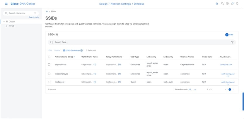
For information about provisioning ISE Settings from Cisco DNA Center, see Provision Cisco ISE Settings from Cisco DNA Center. |
Guest Wireless Network Features Configurable via Cisco DNA Center
| Feature | Type | Description | ||||||||
|---|---|---|---|---|---|---|---|---|---|---|
|
Wireless Network Name (SSID) |
Text Field |
The SSID for the WLAN. |
||||||||
|
WLAN Profile Name |
Text Field |
Cisco DNA Center will take SSID_Profile as default based on SSID Name. You can change the WLAN profile name as per your requirements. |
||||||||
|
Policy Profile Name |
Non Editable |
Policy Profile Name is the same as the WLAN Profile Name and is not editable. Based on the WLAN profile name, Cisco DNA Center automatically generates the policy profile name for the Cisco Catalyst 9800 Series Wireless Controller. |
||||||||
|
WIRELESS OPTION |
Radio Button |
Determines in which RF bands the SSID will be broadcast. The following choices are available:
|
||||||||
|
Primary Traffic Type |
Drop Box |
For Catalyst 9800 Series Wireless Controllers, this setting applies a precious metals QoS SSID policy in both the upstream and downstream direction for the WLAN/SSID. Precious metals policies control the maximum DSCP marking within the CAPWAP header, as traffic is tunneled between the AP and the Cisco Wireless Controller in centralized (local mode) designs. For Cisco AireOS Wireless Controllers, this setting applies the Platinum QoS profile to the WLAN/SSID. Application Visibility is enabled on the WLAN/SSID, but no AVC profile is applied. The Fastlane EDCA profile is set for both the 802.11a/n/ac (5 GHz) and the 802.11b/g/n (2.4 GHz) radios.
|
||||||||
|
Broadcast SSID |
On/Off Toggle |
Determines whether the SSID will be broadcast in wireless beacons and probe responses. The default setting is on. |
||||||||
|
SSID STATE |
On/Off Toggle |
Use this toggle button to turn on or turn off the radios on the APs. When the Admin Status is disabled, the APs remain associated with the wireless controller and are accessible, but the APs still require licenses. |
||||||||
|
LEVEL OF SECURITY L2 Security |
Radio Button |
Determines the Layer 2 (L2) security settings for the WLAN. Choose the encryption and authentication type for the network. The sites, buildings, and floors inherit settings from the global hierarchy. You can override the level of security at the site, building, or floor level. The following choices are available:
|
||||||||
|
LEVEL OF SECURITY L3 security |
Radio Button |
Determines the Layer 3 security settings for the WLAN. The following options are available:
|
||||||||
|
AUTHENTICATION SERVER |
Drop Box |
This selection is only available if Web Auth is selected within LEVEL OF SECURITY. Determines the web portal and authentication server for Web Auth.
|
||||||||
|
AUTHENTICATION SERVER > ISE Authentication > What kind of portal are you creating today? |
Drop-down Menu |
The selection is only available if ISE Authentication is chosen. Determines the type of guest portal that will be created within the Cisco ISE server. The following options are available:
|
||||||||
|
AUTHENTICATION SERVER > ISE Authentication > Where will your guests redirect after successful authentication? |
Drop-down Menu |
This selection is only available if ISE Authentication is selected. Determines what web page is displayed after guests have successfully authenticated to the network. The following options are available:
|
||||||||
|
AUTHENTICATION SERVER > External Authentication > Web Auth URL? |
Text Field |
This selection is only available if External Authentication is selected. Specifies the URL of the Web Auth server. The guest will be redirected to this URL to be authenticated to the network. |
||||||||
|
Configure AAA |
Link |
Click Configure AAA to add and configure the AAA servers for the enterprise wireless network SSID. Choose Authentication, Authorization, and Accounting server from Drop Box. Click + to add a server.
From the Additional Server drop-down list, choose the server IP address. To use the AAA server for accounting, check the Copy Same Servers for Accounting check box. To configure a different accounting server for an SSID, do the following:
Cisco DNA Center allows you to override the set of AAA server configurations for the SSID at the site level. For each set of overridden AAA settings per SSID, Cisco DNA Center creates a new WLAN profile with the corresponding AAA servers mapped to it. If an SSID is overridden for different floors, and you make changes in the AAA servers, Cisco DNA Center creates the new WLAN profiles equal to the number of floors. You must reprovision the device to override the AAA servers at the site level. |
||||||||
|
Mac Filtering |
Check Box |
Check this check box to enable MAC-based access control or security in the wireless network.
|
||||||||
|
AAA Override |
Check Box |
Check box to enable the AAA override functionality. By default, this check box is dimmed. You must configure an AAA server using the Configure AAA option to use this check box. |
||||||||
|
Timeout Settings for Sleeping Clients |
Select radio button |
If you choose Web Authentication Internal, Web Authentication External, Web Passthrough Internal, or Web Passthrough External for Timeout Settings for sleeping clients, choose one of the following authentication options: Always authenticate: Enables authentication for sleeping clients. Authenticate after: Enter the duration for which sleeping clients are to be remembered before reauthentication becomes necessary. The valid range is from 10 minutes through 43,200 minutes, and the default duration is 720 minutes.
|
||||||||
|
Deny RCM Clients |
Check Box |
Check this check box to deny clients with randomized MAC addresses. |
||||||||
|
Pre-Auth ACL List Name |
Drop Box |
Choose the ACL list name that you already created to map with the SSID. |
||||||||
|
Fastlane |
Check Box |
This box can only be checked when the Type of Enterprise Network has been chosen as Voice and Data. For Catalyst 9800 Series Wireless Controllers, the Fastlane check box enables Auto QoS in Fastlane mode. Auto QoS in Fastlane mode configures the Fastlane EDCA profile for both the 5 GHz and 2.4 GHz bands. However, no precious metals QoS SSID policy is applied to the WLAN/SSID when the Fastlane check box is selected. For Cisco AireOS Wireless Controllers, this setting enables the Fastlane macro for the WLAN/SSID. The Fastlane macro applies the Platinum QoS profile to the WLAN/SSID. Application Visibility is enabled on the WLAN/SSID with the AVC profile named AUTOQOS-AVC-PROFILE. The QoS Map is modified to trust DSCP in the upstream direction. In the downstream direction, Cisco best practices are implemented when mapping DSCP-to-UP values. |
||||||||
|
Advanced Settings – Session timeout |
Check Box and Integer Field |
Configures the maximum time for a client session to remain active before requiring reauthorization. The range is between 300 and 86,400 seconds (5 minutes and 24 hours). The default is enabled with a time of 1800 seconds (30 minutes). |
||||||||
|
Advanced Settings – Client Exclusion |
Check Box and Integer Field |
Configures the amount of time a wireless client is excluded from attempting to authenticate after maximum authentication failures has been exceeded. The default is enabled with a time of 180 seconds (3 minutes). |
||||||||
|
Advanced Settings – MFP CLIENT PROTECTION |
Radio Button |
Additional security setting that controls the use of 802.11w Protected Management Frames for the WLAN. The following options are available:
|
||||||||
|
Advanced Settings – 11k Neighbor List |
Check Box |
Controls the use of 802.11k Assisted Roaming neighbor lists for the WLAN, which can limit the need for passive and active scanning by the wireless client. The default setting is enabled for the band (5 GHz or 2.4 GHz) with which the client is associated. |
||||||||
|
Advanced Settings – 11v BSS TRANSITION SUPPORT |
Multiple Check Boxes and Integer Field |
Additional settings for support of 802.11v Wireless Network Management (WNM) for the WLAN. The following settings are available:
|
||||||||
|
NAS-ID |
Drop-down List |
From the NAS-ID Opt drop-down list, choose the required type of network access server identifier (NAS ID). To specify a custom script for the NAS ID, choose Custom Option from the NAS-ID Opt drop-down list and enter the custom script in the corresponding Custom Script for Opt field. You can enter up to 31 alphanumeric characters, special characters, and spaces for the custom script. Cisco DNA Center does not support the special characters ?, ", < , and trailing spaces for the custom script.
(Optional) Click + to add another NAS ID. You can add up to three NAS IDs. Cisco DNA Center applies only one NAS ID for Cisco AireOS Wireless Controllers. You can overwrite the NAS ID at the site level from . |
||||||||
|
Advanced Settings – Coverage Hole Detection |
Toggle button |
Coverage Hole Detection toggle button to enable or disable the coverage hole detection functionality. |
||||||||
|
Advanced Settings – Client Rate Limit |
Integer Field |
To configure the Client Rate Limit, enter a value for the client rate limit in bits per second. The valid range is from 8000 through 100,000,000,000. The value must be a multiple of 500.
The following are the valid ranges for a client rate limit on Cisco IOS XE devices:
|
||||||||
|
Advanced Settings – Radius Client Profiling |
Toggle button |
For Radius Client Profiling, use this toggle button to enable or disable RADIUS profiling on a WLAN.
|
||||||||
|
Advanced Settings – CCKM |
Toggle button |
Configure CCKM: Use this toggle button to enable CCKM as the authentication key management option in Cisco DNA Center. Timestamp Tolerance: This field is visible only if you enable CCKM. Enter the CCKM tolerance level. The CCKM tolerance level is not applicable for the Cisco AireOS Wireless Controller platform.
|
||||||||
|
Advanced Settings – Protected Management Frame (802.11w) |
Radio Button |
The options available under Protected Management Frame (802.11w) vary based on the settings that you chose under Level of Security. The following options may be available:
|
Guest Wireless Network Settings Configured in the Deployment Guide
| Feature | Settings |
|---|---|
|
Wireless Network Name (SSID) |
lab3guest5 |
|
Broadcast SSID |
On |
|
Admin Status |
On |
|
Wireless Option |
Multi band operation (2.4 GHz, 5 GHz, 6 GHz) |
|
Primary Traffic Type |
Best Effort (Silver) |
|
LEVEL OF SECURITY |
Web Auth |
|
AUTHENTICATION SERVER |
ISE Authentication |
|
AUTHENTICATION SERVER > ISE Authentication > What kind of portal are you creating today? |
Self Registered |
|
AUTHENTICATION SERVER > ISE Authentication > Where will your guests redirect after successful authentication? |
Original URL |
|
Configure AAA |
AAA configured |
|
AAA Override |
Enabled |
|
Mac Filtering |
Checked |
|
Fastlane |
Unchecked |
|
Deny RCM Clients |
Unchecked |
|
Pre Auth ACL |
Select configured Pre auth ACL |
|
Advanced Settings – FAST TRANSITION (802.11r) |
Disabled |
|
Advanced Settings – MFP CLIENT PROTECTION |
Optional |
|
Advanced Settings –Protected Management Frame |
Disabled |
|
Advanced Settings – Session timeout |
Checked, 1800 seconds |
|
Advanced Settings – Client Exclusion |
Checked, 180 seconds |
|
Advanced Settings – MFP CLIENT PROTECTION |
Optional |
|
Advanced Settings – 11k Neighbor List |
Checked |
|
Advanced Settings – Radius Client Profiling |
Unchecked |
|
Advanced Settings – Configure Client Rate Limit |
Blank |
|
Advanced Settings – Coverage Hole Detection |
Checked |
|
Configure CCKM |
Unchecked |
|
NAS-ID |
Blank |
|
Advanced Settings – 11v BSS TRANSITION SUPPORT |
BSS Max Idle Service – Checked Client Idle User Timeout – Checked, 300 seconds Directed Multicast Service - Checked |
Provision Cisco ISE Settings from Cisco DNA Center
When a guest SSID profile is assigned to a site, Cisco DNA Center will push the required authentication, authorization, and guest portal configurations to Cisco ISE according to the settings in the guest SSID profile.
Procedure
|
Step 1 |
Choose Lab3_Guest_Portal to verify the portal details. 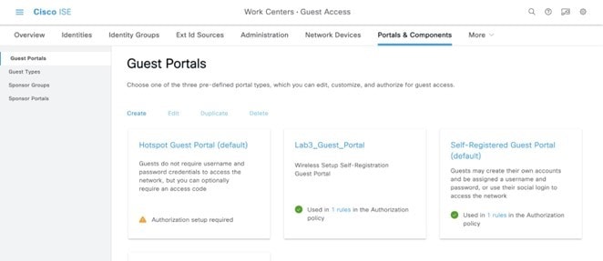
ISE will display a new guest portal named Lab3_Guest_Portal. . |
|
Step 2 |
Click the 1 rules link to check the authorization policy created by Cisco DNA Center. 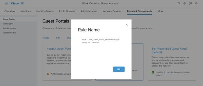
|
|
Step 3 |
From the top-left corner, click the menu icon and choose . |
|
Step 4 |
Click Default. |
|
Step 5 |
Go to Authorization Policy to verify the authorization policy pushed by Cisco DNA Center. 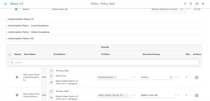
|
Remote Office Wireless Deployment Settings
This section provides an overview of a remote office wireless network using APs in FlexConnect mode, which will be provisioned using Cisco DNA Center.
The site hierarchy consists of the following:
-
A branch area (New York) with a building (Branch 5) and multiple floors (Floor 1, Floor2, and Floor 3).
-
An SSID for employee traffic (lab3branch5) and an SSID for guest traffic (lab3guest5), both advertised by the APs within the branch.
-
A non-Cisco SDA (legacy) remote office wireless deployment, in which all employee branch wireless traffic is centrally switched.
The guest wireless traffic within the branch is locally switched. Cisco Wireless Controllers will be in N+1 HA mode and must be assigned to sites during the Cisco DNA Center provisioning process.
Note |
For this deployment guide, both Catalyst 9800-40 wireless controllers (C9800-Flex-CVD and C9800-CVD-Nplus1) will be assigned to building Branch 5 within the New York area. |
Within Cisco DNA Center, sites (areas, buildings, or floors) containing APs are assigned as either primary managed AP locations or secondary managed AP locations. There can be only one primary enterprise wireless controller assigned to a site at a given time, meaning that a site can only be assigned as a primary managed AP location for one enterprise wireless controller at a time. For this deployment guide, APs on Floor 1 within Branch 5, will be provisioned to C9800-Flex-CVD through Cisco DNA Center.
Cisco DNA Center supports the configuration of AP high availability, in which the AP tries to associate with primary and secondary wireless controllers and form a CAPWAP control connection. If the primary wireless controller is unavailable, the AP will attempt to establish a CAPWAP control connection to the secondary wireless controller. In Cisco DNA Center, this is accomplished by configuring sites containing APs as secondary managed AP locations.
Note |
For this design and deployment guide, wireless controller C9800-Flex-CVD will be provisioned so that Floor 1 of Branch 5 is a primary managed AP location. For the APs within Branch 5, wireless controller C9800-CVD-Nplus1 will serve as the secondary wireless controller in an N+1 wireless controller redundancy configuration. |
Recommendations
When configuring the remote office wireless deployment settings, consider the following recommendations:
-
Use PortFast on AP switch ports for APs in FlexConnect mode, supporting only the central switched WLANs. To configure the switch port for PortFast, set the port to be connected as a host port, using the switch port host command or the PortFast command. This configuration allows for a faster AP join process. There is no risk of loops, as the local mode APs never directly bridge traffic between VLANs. You can set the port directly on access mode.
-
For APs in FlexConnect mode, when using locally switched WLANs mapped to different VLANs (the AP switch port is in trunk mode), prune or limit the VLANs present on the port to match the AP-configured VLANs.
Configure Wireless Interface
In Cisco DNA Center, the enterprise and guest WLANs terminate on the wireless interfaces known as Ethernet VLAN interfaces. The following table shows the wireless interfaces created for this design and deployment guide for the enterprise and guest WLANs.
| Name | VLAN | Usage |
|---|---|---|
|
branchemployee |
100 |
VLAN for centrally switched employee traffic. |
|
branchguest-dmz |
110 |
VLAN for guest traffic locally switched on a VLAN on switch. |
Note |
The native VLAN (AP VLAN) configuration is specific to FlexConnect AP deployments. The FlexConnect locally switched traffic terminates on a specific VLAN, which is configured in the wireless profile for this design and deployment guide. Therefore, the field will be left blank. |
The following steps explain how to configure wireless interfaces within Cisco DNA Center.
Before you begin
To complete this action, you must have SUPER-ADMIN-ROLE or the NETWORK-ADMIN-ROLE privileges.
Procedure
|
Step 1 |
Login to Cisco DNA Center web console using the IP address or fully qualified domain name of your instance. Example: |
|
Step 2 |
From the top-left corner, click the menu icon and choose . The Wireless Network Settings dashboard is displayed. An example is shown in the following figure. 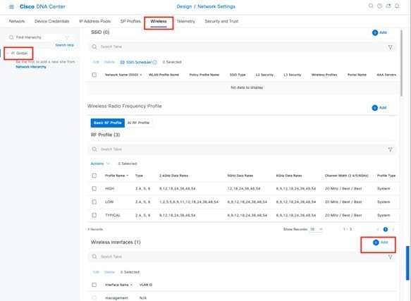
|
|
Step 3 |
Enter the Interface Name and VLAN ID for the wireless interface corresponding to the enterprise VLAN (branchemployee). |
|
Step 4 |
Click Add. 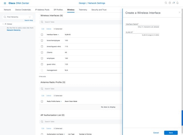
Repeat the procedure to add the wireless interface for the guest VLAN (guest-dmz). When completed, the two new wireless interfaces should appear in the Wireless Network Settings dashboard, as shown in the figure below: 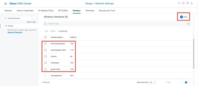
|
Configure Enterprise Wireless SSID
Enterprise wireless networks are the nonguest WLAN/SSIDs that are available for broadcast across the deployment. You must define them at the global level of the site hierarchy. Once defined, you can apply the enterprise wireless networks to wireless profiles and assign wireless profiles to one or more sites within the hierarchy.
For the design and deployment guide, a single enterprise WLAN SSID named lab3branch5 is provisioned.
Procedure
|
Step 1 |
From the top-left corner, click the menu icon and choose . |
||
|
Step 2 |
Click SSIDs. |
||
|
Step 3 |
Hover your cursor over + Add and choose Enterprise. The Basic Settings window is displayed. 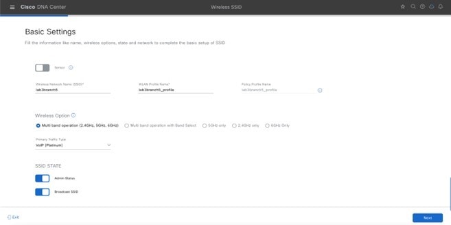
For information about features that can be configured for enterprise wireless networks via Cisco DNA Center, see Enterprise Wireless Network Features Configurable via Cisco DNA Center. |
||
|
Step 4 |
Enter the information for the Basic Settings and click Next.
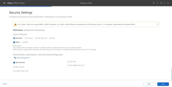
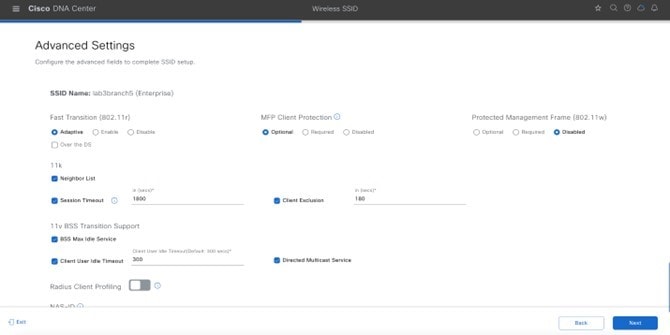
|
||
|
Step 5 |
Click + Add to add a new wireless profile.
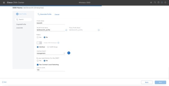
|
||
|
Step 6 |
Enter the Wireless Profile Name. For this deployment guide, create a wireless profile named branch5. |
||
|
Step 7 |
(Skip this step if SD-Access App is not deployed.) Under Fabric, select No. The Select Interface field is displayed. This deployment guide only discusses non-SDA wireless deployments using Cisco DNA Center. |
||
|
Step 8 |
From the Select Interface drop-down menu, choose branchemployee. |
||
|
Step 9 |
Check the box next to FlexConnect Local Switching. |
||
|
Step 10 |
Enter VLAN ID 100 in Local to VLAN. For terminating branch employee traffic, you have selected the branchemployee interface on the enterprise wireless controller, but all branch employee traffic will be locally switched onto VLAN 100 of the branch switch. |
||
|
Step 11 |
Click Next. The Summary page displays SSID basic settings, security, advanced settings, and network profiles. |
||
|
Step 12 |
Click Save.
|
||
|
Step 13 |
Click Configure Network Profiles. |
||
|
Step 14 |
Click Assign Sites in branch network profiles. |
||
|
Step 15 |
Select the New York area. All of the child site locations are automatically selected: Building 23 with Floor 1, Floor 2, and Floor 3 and Building 24 with Floor 1, Floor 2, and Floor 3. |
||
|
Step 16 |
Click OK to close the site hierarchy side panel and return to the Create a Wireless Profile side panel. 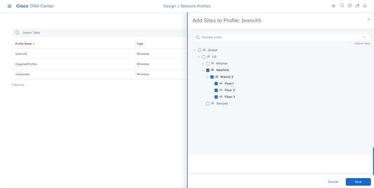
|
||
|
Step 17 |
Click + Add under Attach Template(s) to add the CLI-based templates to the enterprise wireless network configuration.
The new enterprise wireless network, lab3branch5, appears in the Wireless Network Settings dashboard. |
Configure FlexConnect Settings
The following procedure describes the steps to configure the FlexConnect settings using Cisco DNA Center, which is where the native VLAN and the client VLAN can be set.
Procedure
|
Step 1 |
From the top-left corner, click the menu icon and choose . 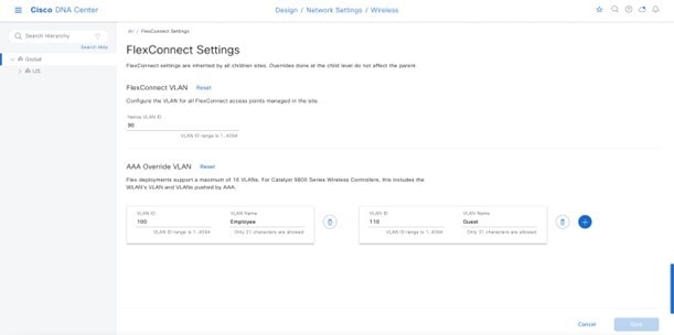
|
||
|
Step 2 |
Configure Native VLAN and AAA override VLAN in the global settings.
|
Configure FlexConnect in the Model Config Editor
Model configs are a set of model-based, discoverable, and customizable configuration capabilities, which you can deploy on your network devices with high-level service intent and device-specific CLI templates. The following procedure describes the steps to perform a model config for FlexConnect.
Procedure
|
Step 1 |
From the top-left corner, click the menu icon and choose . |
|
Step 2 |
Click Flex Configuration. |
|
Step 3 |
Click Add and enter the design name. For example, enter branch as the design name. |
|
Step 4 |
Enable IP Overlap. 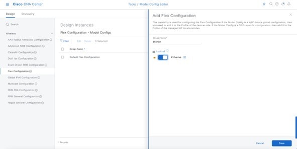
|
Map FlexConnect Model Config to Network Profiles
Procedure
|
Step 1 |
From the top-left corner, click the menu icon and choose . |
|
Step 2 |
Click Edit branch5 network profile. |
|
Step 3 |
Click the Model Config tab, and then click Add Model Config. |
|
Step 4 |
Choose Wireless Controller as the Device Type. |
|
Step 5 |
Click Wireless > Flex Configuration, and then select the configured model config. |
|
Step 6 |
Click Add and save the changes. 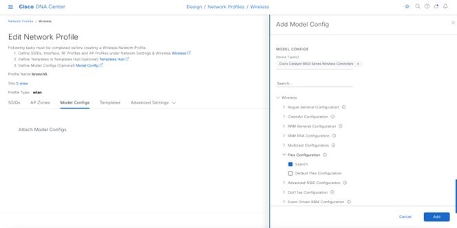
|
Configure Guest Wireless SSID
Guest wireless networks must be defined at the global level of the site hierarchy. Once defined, guest wireless networks are applied to wireless profiles. Wireless profiles are then assigned to one or more sites within the hierarchy. For this deployment guide, a single guest wireless network (SSID) named lab3guest5 is provisioned.
Procedure
|
Step 1 |
|||||
|
Step 2 |
From the top-left corner, click the menu icon and choose . |
||||
|
Step 3 |
Click SSIDs. |
||||
|
Step 4 |
Hover your cursor over + Add and choose Guest. The Basic Settings window is displayed. 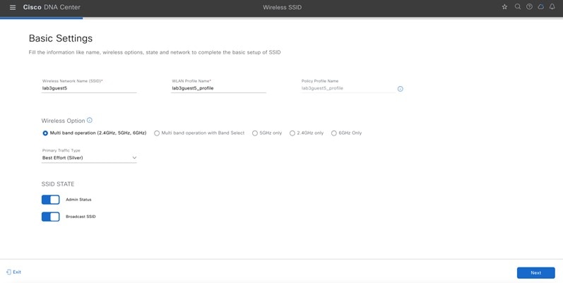
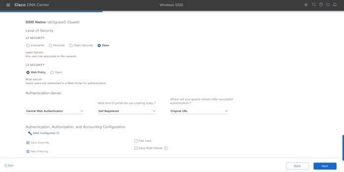
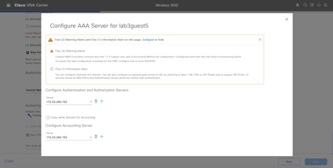
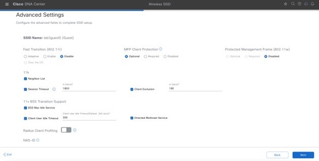
For information about features that can be configured for guest wireless networks via Cisco DNA Center, see Guest Wireless Network Features Configurable via Cisco DNA Center. |
||||
|
Step 5 |
Enter the information for the relevant fields and click Next.
|
||||
|
Step 6 |
Attach the guest wireless network to the existing branch5 wireless profile. 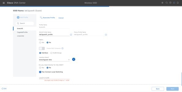
|
||||
|
Step 7 |
From the Select Interface drop-down menu, choose branchguest-dmz. The guest traffic on the branchguest-dmz VLAN (VLAN 110) will be terminated. |
||||
|
Step 8 |
Click FlexConnect Local switching and enter Local Vlan 110. |
||||
|
Step 9 |
Click Next. The Portal Customization page is displayed. 
|
||||
|
Step 10 |
Click Create Portal to add a new guest portal in Cisco ISE. The Portal Builder page is displayed. You have the option to leave without portal creation. 
|
||||
|
Step 11 |
Enter the relevant information. You must at least name the guest portal. For this deployment guide, the portal has been named Lab3_Guest_Portal. The drop-down menu in the Portal Builder allows you to customize the Login Page, Registration Page, Registration Success, and Success Page of the portal. You can customize the color scheme, fonts, page content, logo, and background for the web portal. You can also preview the portal to see what it will look like on a smart phone, tablet, and computer. |
||||
|
Step 12 |
Click Save to create the new guest portal on the Cisco ISE server and return to the guest wireless network workflow. |
||||
|
Step 13 |
Click Next. The summary page will show SSID basic settings, security, advanced settings, and network profiles. 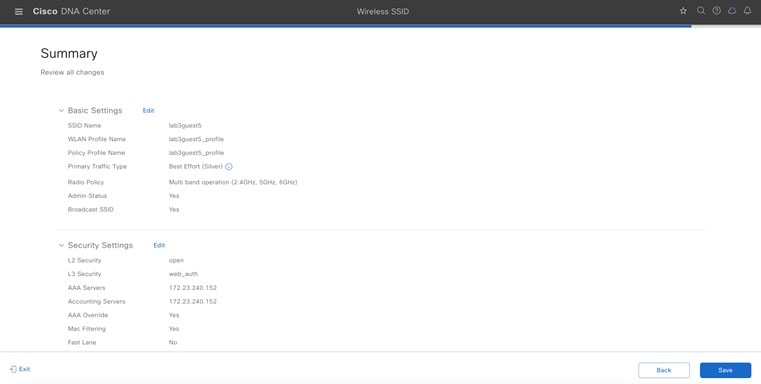
|
||||
|
Step 14 |
Click Save. |
||||
|
Step 15 |
Click Configure Network Profiles. |
||||
|
Step 16 |
Click Assign Sites in Branch Network Profiles. |
||||
|
Step 17 |
Select the New York area. This should automatically check the child site locations: Branch 5 with Floor 1, Floor 2, and Floor 3. Automatically, the child site locations are selected: Branch 5 with Floor 1, Floor 2, and Floor 3. |
||||
|
Step 18 |
Click OK to close the site hierarchy side panel and return to the Create a Wireless Profile side panel. 
|
||||
|
Step 19 |
Click + Add under Attach Template(s) to add the CLI-based templates to the enterprise wireless network configuration.
The new enterprise wireless network, lab3branch5, is displayed in the Wireless Network Settings window.
|
Configure FlexConnect Settings for Guest SSID
The following procedure describes how to configure the FlexConnect settings for a guest SSID.
Procedure
|
Step 1 |
From the top-left corner, click the menu icon and choose . |
||
|
Step 2 |
Configure native VLAN and AAA override VLAN in global settings.
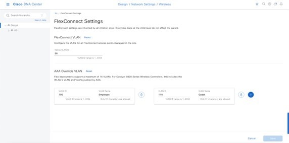
|
Configure Model Config Editor for Flex Guest SSID
Procedure
|
Step 1 |
From the top-left corner, click the menu icon and choose . |
|
Step 2 |
Click Flex Configuration. |
|
Step 3 |
Click Add and provide design name as branch. |
|
Step 4 |
Enable IP Overlap. 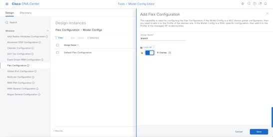
|
Map Flex Guest SSID Model Config to Network Profiles
Procedure
|
Step 1 |
From the top-left corner, click the menu icon and choose Design > Network Profile. |
|
Step 2 |
Choose the Edit branch5 network profile. |
|
Step 3 |
Click Model Config and add a model config. |
|
Step 4 |
For Device Type, choose wireless controller. |
|
Step 5 |
Click and choose the configured model config. |
|
Step 6 |
Click Add and save the changes. 
|
Customize Wireless RF Profiles
The Wireless Radio Frequency Profile section of the Wireless Settings dashboard allows you to do the following:
-
Visually inspect the settings for each of the three preconfigured RF profiles within Cisco DNA Center. These RF profiles are also preconfigured within the Cisco Catalyst 9800 Series Wireless Controller.
-
Create custom RF profiles in which you can fine tune various RF aspects of your wireless deployment.
-
Choose either a preconfigured or custom RF profile as the default RF profile that is assigned to APs within Cisco DNA Center.
When provisioning APs in Cisco DNA Center, the default RF profile configured within the Wireless Settings dashboard will be applied. However, you can also override this setting for each AP.
The following preconfigured RF profiles are available:
-
LOW: This profile tunes the RF attributes in both bands (2.4 GHz and 5 GHz) for low client density deployments.
-
TYPICAL: This profile tunes the RF attributes in both bands (2.4 GHz and 5 GHz) for medium client density deployments.
-
HIGH: This profile tunes the RF attributes in in both bands (2.4 GHz and 5 GHz) for high client density deployments, such as stadiums, auditoriums, etc.
Note |
Appendix D explains the specific settings within each of the three preconfigured RF profiles within Cisco DNA Center. Set the desired TPC threshold on the RF group, based on the AP density and installed height. For large deployments, there can be significant variations in the RF environment, so it is important to properly adjust TPC to ensure optimal coverage in each location. Together with transmit power, data rates are the primary mechanism to influence the client roaming behavior. Changing data rates to the lowest mandatory rate can modify when the client may trigger a new roam, which is especially important for large open spaces that suffer from sticky client problems. When setting up RF profiles, try to avoid configuring adjacent AP groups and RF profiles with different DCA channel sets, as this can negatively impact DCA calculations. Users can add a nonsupported channel to the RF profile DCA list, even if the channel is not supported in the configured regulatory domain. The recommendation is to always check if the configured channels are allowed in the country domain. There is no impact on network operations because the DCA would not assign the unsupported channels to the APs. However, starting in release 17.5, the C9800 has a validation to check if the added channels are allowed. |
Procedure
|
Step 1 |
From the Wireless Network Settings dashboard, locate the Wireless Radio Frequency Profile section. The Wireless Radio Frequency Profile section of the Wireless Settings dashboard can only be accessed at the global level of the site hierarchy. |
|
Step 2 |
By default, the TYPICAL RF profile is set as the default RF profile. You will know this because it will appear as TYPICAL (Default) as shown in the following figure. To change the RF profile, check the check box next to the name of one of the available profiles, and then click the ✓ default button. 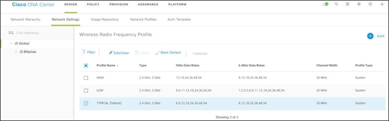
For this design and deployment guide, the TYPICAL RF profile was selected, indicating that the deployment is meant for an environment with medium client density. The FlexConnect design for a remote office is now complete. |
Design the Cisco Catalyst 9800-CL Wireless Controller Hosted on AWS
This section describes the wireless controller hosted on AWS deployment, which uses a cloud-based Cisco Catalyst 9800-CL Wireless Controller hosted on AWS. For more information, see Deployment guide for Cisco Catalyst 9800 Wireless Controller for Cloud (C9800-CL) on Amazon Web Services (AWS).
Launching a Cisco Catalyst 9800 Amazon Machine Image (AMI) occurs directly from the AWS Marketplace. The Cisco Catalyst 9800 Series Wireless Controller will be deployed on an Amazon EC2 in an Amazon Virtual Private Cloud (VPC).
Cisco supports the following instance type for the first release of the Cisco Catalyst 9800 Series Wireless Controller on the cloud:
C5.xlarge: 4 vCPUs, 8 GB RAM, 8GB Disk with 1 vNIC.
The allocated resources will allow the instance to scale to 1000 APs and 10,000 clients.
Prerequisites for Deploying the Cisco Catalyst 9800-CL Wireless Controller on AWS
-
Create a managed VPN connection from the corporate network to the VPC.
-
Create a VPC with the desired subnet for the wireless management interface on the Catalyst 9800 Series Wireless Controller.
-
Catalyst 9800 Series Wireless Controller CloudFormation template: You do not have to configure the CloudFormation template because the template is automatically integrated in the launching procedure. If desired, you can download and view the CloudFormation template file from the AWS Marketplace page for the product.
-
Amazon Machine Instance ID (AMI-ID) for the desired Catalyst 9800 Series Wireless Controller software release: The AMI will be available in the AWS marketplace.
-
AP access can be restricted to your instance for security reasons. For example, CAPWAP from a single, specific IP range can be allowed so that only those APs are able to register to the controller. The following table shows the ports that need to be opened in the firewall to allow the AP to communicate with the wireless controller on AWS.
| Ports | Protocol |
|---|---|
|
UDP 5246/5247/5248 |
CAPWAP |
|
TCP 22 |
SSH, SCP |
|
TCP 21 |
FTP |
|
ICMP |
Ping |
|
UDP 161, 162 |
SNMP/SNMP Traps |
|
TCP 443/80 |
HTTPs/HTTP |
|
TCP/UDP 49 |
TACACS+ |
|
UDP 53 |
DNS Server |
|
UDP 1812/1645/1813/1646 |
Radius |
|
UDP 123 |
NTP Server |
|
UDP 514 |
Syslog |
Install the Cisco Catalyst 9800-CL Wireless Controller on AWS
Procedure
|
Step 1 |
Navigate to the AWS Marketplace. |
|
Step 2 |
Locate the Cisco Catalyst 9800-CL Wireless Controller product page by searching the AWS Marketplace for "C9800-CL." |
|
Step 3 |
Choose the Cisco Catalyst 9800-CL Wireless Controller for Cloud and click Continue to Subscribe. |
|
Step 4 |
Choose the fulfillment option: Cloud Formation Template (recommended) or Amazon Machine Image (AMI). If you choose AMI, you can use the AWS Console or the AWS Marketplace interface. For both fulfillment options, you will be guided through the steps to launch a new Catalyst 9800-CL Wireless Controller instance. |
|
Step 5 |
During the installation process, you will be prompted to select the following:
|
|
Step 6 |
Click Review and Launch and ensure that the information is accurate. |
|
Step 7 |
Click Launch Instances. |
|
Step 8 |
Go to AWS Console > EC2 services and wait for your instance to indicate a state of running. You will have to wait a few minutes before you can connect to your Catalyst 9800-CL Wireless Controller instance. |
|
Step 9 |
Connect to the IP address assigned to your Catalyst 9800-CL Wireless Controller instance and use the WebUI wizard for Day 0 configuration and setup. |
|
Step 10 |
Alternatively, connect to your instance using an SSH client, providing the necessary credentials or the private SSH key selected during setup. For example: |
|
Step 11 |
Once SSH has connected, you should see the IOS XE command prompt on the Catalyst 9800-CL Wireless Controller. You may now begin configuring your instance. |
Configure Enterprise Wireless Networks (SSIDs)
Wireless settings are hierarchical. Settings at lower levels of the site hierarchy can override settings defined in higher levels. By default, you are taken to the global level, which is the highest level of the site hierarchy.
Enterprise wireless networks are the nonguest WLANs/SSIDs that are available for broadcast across the deployment, and these networks must be defined at the global level of the site hierarchy. Once defined, enterprise wireless networks are applied to wireless profiles, which are assigned to one or more sites within the hierarchy. For this design and deployment guide, a single enterprise WLAN/SSID named corpevent is provisioned. The following steps explain how to configure the enterprise wireless network within Cisco DNA Center.
Before you begin
To complete this action, your user profile must be assigned the SUPER-ADMIN-ROLE or the NETWORK-ADMIN-ROLE.
Procedure
|
Step 1 |
Log in to the Cisco DNA Center web console using an IP address or a fully qualified domain name. Example:http://<Cisco_DNA_Center_IPaddr_or_FQDN> |
||||||||||||||||||||||||||||||||||||||||
|
Step 2 |
From the top-left corner, click the menu icon and choose . |
||||||||||||||||||||||||||||||||||||||||
|
Step 3 |
From the Wireless Network Settings dashboard, hover your cursor over + Add and choose Enterprise. The Create an Enterprise Wireless Network dialog box is displayed. 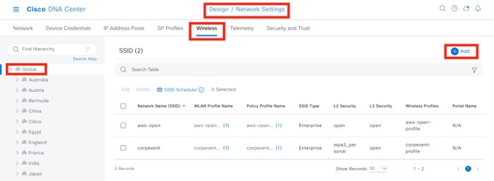
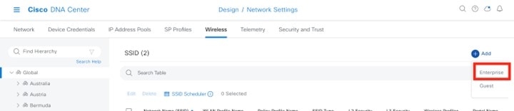
|
||||||||||||||||||||||||||||||||||||||||
|
Step 4 |
Enter the necessary information and click Next. The settings used in this deployment are provided in the following table.
|
||||||||||||||||||||||||||||||||||||||||
|
Step 5 |
The next page in the workflow is displayed. You can attach the enterprise wireless network to an existing wireless profile, or you can create a new wireless profile and attach the enterprise wireless network. |
||||||||||||||||||||||||||||||||||||||||
|
Step 6 |
Click Add to add a new wireless profile. 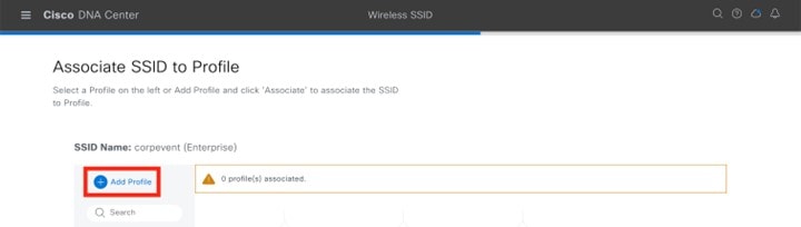
|
||||||||||||||||||||||||||||||||||||||||
|
Step 7 |
In the Wireless Profile Name field, enter the name of the new wireless profile. For this deployment guide, a wireless profile named corpevent-profile was created. |
||||||||||||||||||||||||||||||||||||||||
|
Step 8 |
From Fabric, click the No radio button. This deployment guide only discusses non-SDA wireless deployments using Cisco DNA Center. When you choose No, the Select Interface field is automatically displayed. |
||||||||||||||||||||||||||||||||||||||||
|
Step 9 |
From the Select Interface drop-down list, choose Management.
|
||||||||||||||||||||||||||||||||||||||||
|
Step 10 |
Check the FlexConnect Local Switching check box. |
||||||||||||||||||||||||||||||||||||||||
|
Step 11 |
In the Local to VLAN field, enter VLAN ID 16. All branch employee traffic will be locally switched onto VLAN 16 of the branch switch. 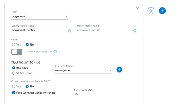
|
||||||||||||||||||||||||||||||||||||||||
|
Step 12 |
Click Associate Profile to attach the profile to wireless SSID. 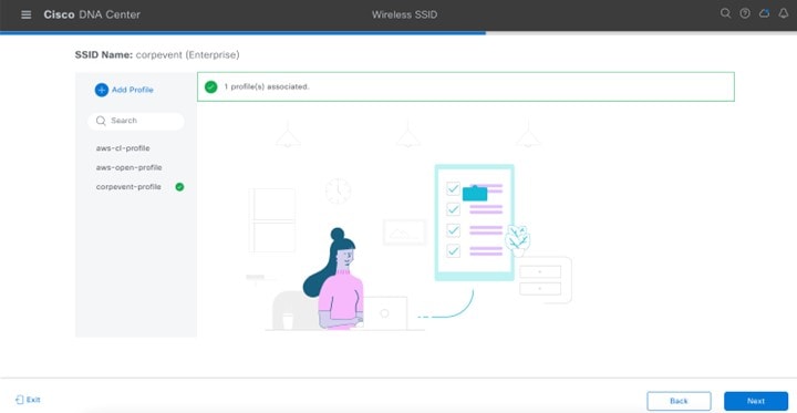
|
||||||||||||||||||||||||||||||||||||||||
|
Step 13 |
Click Next to review the summary, and then click Save. 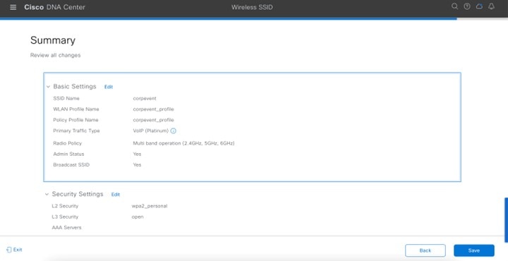
|
||||||||||||||||||||||||||||||||||||||||
|
Step 14 |
Click Configure Network Profile to go to the Network Profiles page to assign the site for the wireless profile. 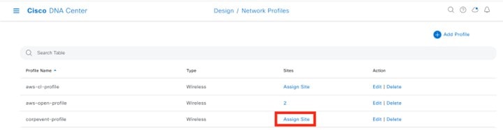
|
||||||||||||||||||||||||||||||||||||||||
|
Step 15 |
Click Assign Site. |
||||||||||||||||||||||||||||||||||||||||
|
Step 16 |
In the left hierarchy tree, choose Global > Milpitas area. The child site locations are automatically selected: Branch 5 and Floor 1 and Floor 2. |
||||||||||||||||||||||||||||||||||||||||
|
Step 17 |
Click OK to close the site hierarchy side panel and return to Create a Wireless Profile. The design of the wireless controller on AWS is complete, and you can go to the Deploy the wireless network section. |
Deploy the Wireless Network
This section of the design and deployment guide implements the use case discussed in the Solution Overview section of this document. Cisco DNA Center is used to automate the deployment of the wireless profile created in the Design the wireless network section of this document to a Cisco Catalyst 9800-40 enterprise wireless controller HA SSO pair (WLC-9800-2) and a Cisco Catalyst 9800-CL guest wireless controller (WLC-9800-CL).
This section contains the following topics and processes:
-
Discover and manage the Catalyst 9800 Series Wireless Controllers
-
Manage software images for the Catalyst 9800 Series Wireless Controllers
-
Use software image management (SWIM) to update the Catalyst 9800 Series Wireless Controller software
-
Configure high availability (HA) stateful switch-over (SSO) on the Catalyst 9800-40 enterprise wireless controllers
-
Provision the Catalyst 9800-40 enterprise wireless controller HA SSO pair
-
Provision the Catalyst 9800-CL guest anchor wireless controller
-
Join the new APs to the enterprise wireless controller HA SSO pair
-
Provision the new APs
-
Position the new APs on the floor map
-
Local RRM Vs cloud-based RRM
-
Enable cloud-based RRM
-
Template programmer for additional wireless configurations
Enterprise WLAN for Campus Wireless Deployment
This section explains how to provision the campus wireless deployment for the Milpitas site. For this scenario, the wireless controllers are discovered, and their images are updated and provisioned. These procedures are explained in the following sections.
Discover and Manage the Cisco Catalyst 9800 Series Wireless Controller
This deployment guide uses IP address ranges for discovery of both of the Cisco Catalyst 9800-40 Wireless Controllers deployed as enterprise wireless controllers and the Cisco Catalyst 9800-CL Wireless Controller deployed as the guest wireless controller. Before initiating the discovery, IP connectivity must be enabled to the devices. When using IP address ranges, you can reduce the range to just the wireless controllers to speed the discovery.
Note |
Alternatively, you can supply an initial device for discovery and direct Cisco DNA Center to use Cisco Discovery Protocol (CDP) to find connected neighbors. |
The following assumptions are made for this procedure:
-
The two Catalyst 9800-40 Wireless Controllers (WLC-9800-1 and WLC-9800-2) are connected to the network as standalone wireless controllers. Configuration of the two Catalyst 9800-40 Wireless Controllers into an HA SSO pair will be done within Cisco DNA Center in a later process.
-
NETCONF is enabled on all of the Cisco Catalyst 9800 Series Wireless Controllers (WLC-9800-1, WLC-9800-2, and WLC-9800-CL).
-
All Catalyst 9800 Series Wireless Controllers are on the network, with management IP addresses configured for reachability.
-
SSH access is enabled on all of the Catalyst 9800 Series Wireless Controllers, with a user ID and password configured within the local user database.
-
All Catalyst 9800 Series Wireless Controllers have hostnames configured (WLC-9800-1, WLC-9800-2, and WLC-9800-CL), which will allow the devices to be identified by their hostnames within the Cisco DNA Center inventory after discovery.
For this design and deployment guide, the following table shows the hostnames, platform models, and IP addresses for Cisco DNA Center.
| Hostname | Platform Model | IP Address |
|---|---|---|
|
WLC-9800-1 |
Cisco Catalyst 9800-40 Wireless Controller |
10.4.50.2 |
|
WLC-9800-2 |
Cisco Catalyst 9800-40 Wireless Controller |
10.4.50.22 |
|
WLC-9800-CL |
Cisco Catalyst 9800-CL Wireless Controller |
10.4.48.153 |
This section contains the following processes:
-
Discover the two Catalyst 9800-40 Wireless Controllers, which serve as the enterprise HA SSO pair for the WLAN deployment.
-
Discover the Catalyst 9800-CL Wireless Controller, which serves as the guest anchor wireless controller for the WLAN deployment.
Discover and Manage the Cisco Catalyst 9800-CL Wireless Controller Deployed on AWS
The discovery process is the same for other Cisco Catalyst 9800-CL Wireless Controllers.
Discover the Cisco Catalyst 9800-40 Wireless Controllers Serving as the Enterprise HA SSO Pair for WLAN Deployment
The following steps explain how to discover the Cisco Catalyst 9800-40 Wireless Controllers (WLC-9800-1 and WLC-9800-2).
Procedure
|
Step 1 |
Navigate to the main Cisco DNA Center dashboard. |
|
Step 2 |
From the top-left corner, click the menu icon and choose . The Discovery Dashboard is displayed. 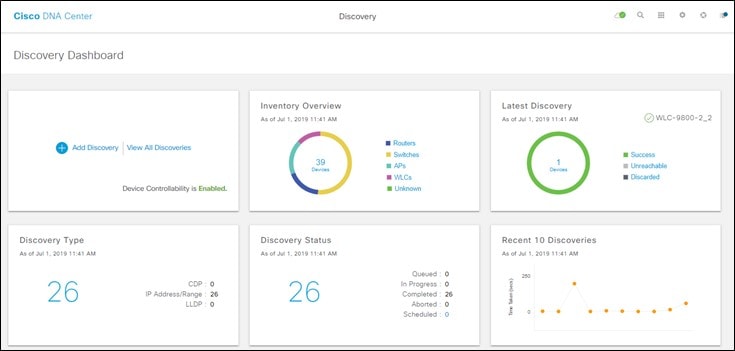
|
|
Step 3 |
Click + Add Discovery to create a new discovery. The New Discovery window is displayed. 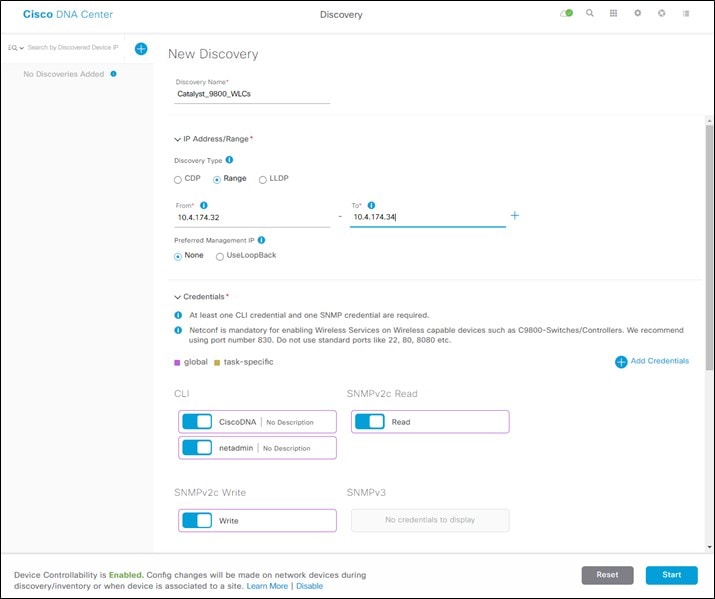
|
|
Step 4 |
From IP Address/Range, for Discovery Type, click the Range radio button. |
|
Step 5 |
In the From field, enter the beginning IP address, and in the To field, enter the ending IP address. The range configured is 10.4.50.2 - 10.4.50.22, which is sufficient to discover the two Catalyst 9800-40 Wireless Controllers (WLC-9800-1 and WLC-9800-2). |
|
Step 6 |
For Preferred Management IP, if a device has a loopback interface used for management, click the Use Loopback radio button. Otherwise, click the None radio button. For this deployment, the VLAN 174 interface is configured as the wireless management interface, so Preferred Management IP is set to None. |
|
Step 7 |
Make sure the CLI, SNMP, and NETCONF credential toggle buttons are set to On. All Catalyst 9800 Series Wireless Controllers require NETCONF for discovery and provisioning. The user ID and password used for NETCONF access to the wireless controllers is the same as the SSH password. |
|
Step 8 |
From the Advanced section, for Protocol Order, check the SSH check box. It is not recommended to enable Telnet because Telnet traffic is sent in clear text across the network, which could pose a security vulnerability. |
|
Step 9 |
Click Start to begin the discovery. The discovery details are displayed while the discovery runs. After discovery is complete, the discovery details are displayed. 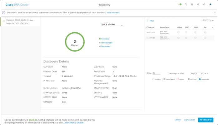
|
|
Step 10 |
After the discovery process is complete, navigate to the main Cisco DNA Center dashboard. |
|
Step 11 |
From the top-left corner, click the menu icon and choose . The list of devices known to Cisco DNA Center will be displayed, including the two Catalyst 9800-40 Wireless Controllers (WLC-9800-1 and WLC-9800-2) that were discovered. The Catalyst 9800-40 Wireless Controllers should show a Last Sync Status of Managed. Cisco DNA Center can now access the devices, synchronize the inventory, and make configuration changes on the devices. |
Discover the Cisco Catalyst 9800-CL Wireless Controller Serving as the Guest Anchor Wireless Controller for WLAN Deployment
To discover the Cisco Catalyst 9800-40 Wireless Controller for the Cisco Catalyst 9800-CL guest Wireless Controller (WLC-9800-CL), repeat the steps in Discover the Cisco Catalyst 9800-40 Wireless Controllers Serving as the Enterprise HA SSO Pair for WLAN Deployment.
For this deployment guide, the IP address range for discovery of the Catalyst 9800-CL guest Wireless Controller (WLC-9800-CL) is a single IP address: 10.4.174.36 - 10.4.174.36.
Note |
Optionally, you can discover all the wireless controllers in a single discovery that includes the IP address range of both the Catalyst 9800-40 enterprise Wireless Controllers (WLC-9800-1 and WLC-9800-2) and the Catalyst 9800-CL guest Wireless Controller (WLC-9800-CL). |
Manage Software Images for the Cisco Catalyst 9800 Series Wireless Controllers
This process is used to upload the latest software images for the Cisco Catalyst 9800 Series Wireless Controllers to the Cisco DNA Center software image repository. The following table shows the platforms and software images uploaded for this deployment.
| Platform | Software Version | Software Image |
|---|---|---|
|
Cisco Catalyst 9800-40 Wireless Controller |
IOS XE Release 17.9.4a |
C9800-40-universalk9_wlc.17.09.04a.SPA.bin |
|
Cisco Catalyst 9800-CL Wireless Controller |
IOS XE Release 17.9.4a |
C9800-CL-universalk9.17.09.04a.SPA.bin |
A minimum of IOS XE release 16.10.1 is required for operability between the Catalyst 9800 Series Wireless Controllers and Cisco DNA Center.
The following procedures are included in this process:
-
Upload the software image for the Cisco Catalyst 9800-40 Wireless Controller.
-
Upload the software image for the Cisco Catalyst 9800-CL Wireless Controller.
Upload the Software Image for the Cisco Catalyst 9800-40 Wireless Controllers
The following steps discuss the image upload process for the Cisco Catalyst 9800-40 Wireless Controllers (WLC-9800-1 and WLC-9800-2).
Procedure
|
Step 1 |
From the top-left corner, click the menu icon and choose . The Image Repository window is displayed in the following figure. 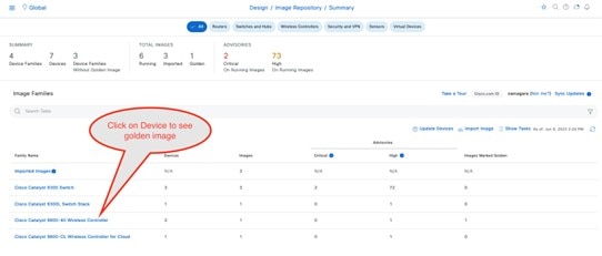
|
|
Step 2 |
You can get a new image into the Cisco DNA Center image repository by doing one of the following:
|
|
Step 3 |
For your desired image, click download image icon. The image will begin to download from the Cisco website. For this deployment guide, image 17.9.4a was downloaded. 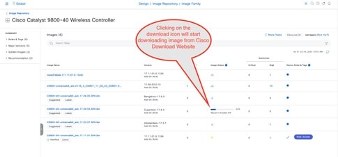
|
|
Step 4 |
Alternatively, click Import to import a new image. The Import Image/Add-on dialog box is displayed. 
|
|
Step 5 |
Click Choose File. |
|
Step 6 |
Navigate to the Catalyst 9800-40 software image on your computer and choose the desired image. For this deployment guide, C9800-40-universalk9_wlc.17.09.04a.SPA.bin was chosen. |
|
Step 7 |
Under Source, click the Cisco radio button because this is a Cisco software image. |
|
Step 8 |
Click Import to upload the image to the Cisco DNA Center image repository. A status bar shows the progress of the upload. Once the upload is complete, the main Image Repository window is displayed. |
|
Step 9 |
Click Show Tasks to verify that the image was imported successfully. The Recent Tasks (Last 50) side panel is displayed. The new image transitions are shown in yellow. The tasks that are completed successfully are shown with a green check mark. |
|
Step 10 |
Close the Recent Tasks (Last 50) side panel. |
|
Step 11 |
From the Image Repository window, click > next to Imported Images to expand the list of imported images. |
|
Step 12 |
Click Assign next to the image file you just uploaded. The Assign Device Family side-in pane is displayed. 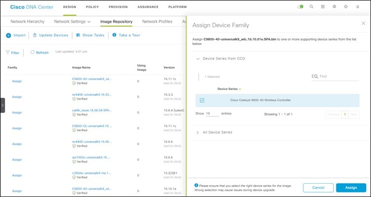
|
|
Step 13 |
Choose the Cisco Catalyst 9800-40 Wireless Controller and click Assign to assign this image to its device family. |
|
Step 14 |
Under the Family column in the list of devices in the main repository window, locate the Catalyst 9800-40 Wireless Controllers and expand the list of available images for the device. You should now see the new image you just uploaded in the list of images available for the device family. |
|
Step 15 |
Click the star for Golden Image to mark the image as the preferred one for the Catalyst 9800-40 Wireless Controller platform. 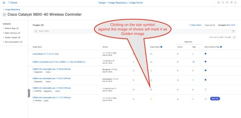
Repeat the entire procedure for the Catalyst 9800-CL guest Wireless Controller (WLC-9800-CL). For this deployment guide, the Catalyst 9800-CL guest Wireless Controller upload image name is C9800-CL-universalk9.17.09.04a.SPA.bin. |
Update the Software Image for the Cisco Catalyst 9800-CL Wireless Controller
This section outlines the procedure for updating the wireless controller image after the image is marked as golden.
Use Software Image Management (SWIM) to Update the Catalyst 9800 Series Wireless Controller Software
This process is used for the following purposes:
-
Distribute (download) the software image from the Cisco DNA Center image repository to the wireless controllers.
-
Upgrade the software images running on the wireless controllers.
Both steps can be run immediately, or the steps can be scheduled to run at a specified date and time to comply with existing network change schedules.
Cisco DNA Center runs a compliance check, which compares the devices in the inventory with images marked as a golden images. Devices that are out of compliance with the golden image are marked as Outdated in the inventory. Before you can update an image to the version marked as golden, the inventory collection must be successfully completed, and the device must be in a Managed state.
The following procedures are included in this process:
-
Upgrade the software images for the Catalyst 9800-40 Wireless Controllers.
-
Upgrade the software image for the Catalyst 9800-CL Wireless Controller.
Upgrade the Software Image for the Cisco Catalyst 9800-40 Wireless Controllers
The following procedure explains how to upgrade the software images for the Cisco Catalyst 9800-40 Wireless Controllers (WLC-9800-1 and WLC-9800-2).
Procedure
|
Step 1 |
From the top-left corner, click the menu icon and choose . |
||
|
Step 2 |
From the Focus drop-down list, choose Software Images. The window displays the software image running on each device in the inventory. 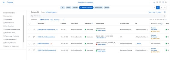
|
||
|
Step 3 |
From the list of devices, locate one of the Catalyst 9800-40 Wireless Controllers (WLC-9800-1 or WLC-9800-2). |
||
|
Step 4 |
Under the Software Image column for the Catalyst 9800-40 Wireless Controller, click Needs Update. The Image Update Readiness Check slide-in pane is displayed. 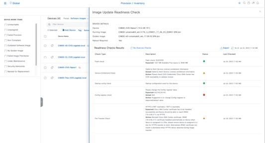
Ensure that the Status column shows either a green icon indicating success or a yellow icon indicating a warning. If any of the checks show a red icon indicating failure, the image on the platform was not upgraded. In this deployment guide, the Config register check shows a red icon because the config register value needs to be 0x2102 or 0x102, but the device is using a value of 0x0. If necessary, correct any issues on the wireless controller which result in a failure. |
||
|
Step 5 |
Click Re-Execute Check to rerun the readiness assessment.
|
||
|
Step 6 |
When you have corrected all checks which indicate a failure, close the Image Update Readiness Check slide-in pane. |
||
|
Step 7 |
Repeat Step 1 through Step 6 for the other Catalyst 9800-40 Wireless Controller. |
||
|
Step 8 |
Check the check boxes for both of the Catalyst 9800-40 Wireless Controllers (Wireless Controller-9800-1 and Wireless Controller-9800-2). |
||
|
Step 9 |
From the Actions drop-down list, choose . The Image Update slide-in pane is displayed.
|
||
|
Step 10 |
Enable Software Activation After Distribution. Alternatively, click the Later radio button and adjust the date and time for the image distribution. Enabling Software Activation After Distribution will activate the image immediately after it is distributed. This action combines the download and activation of the image into a single scheduled process, rather than scheduling download and activation separately. 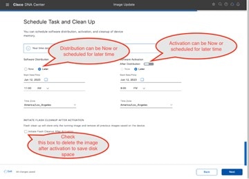
|
||
|
Step 11 |
Click Image Update Status, which takes you to the update progress window. Alternatively, click the menu icon and choose . The scheduled task window is displayed. 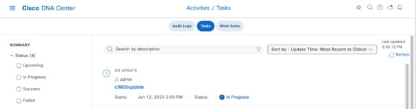
You can expand the task to see the details regarding the distribution and activation of the image. 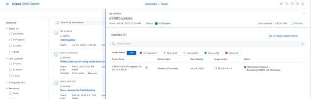
On successful completion of the task, an icon is displayed next to the task, indicating that the update was successful. Again, you can expand the task to see the details regarding the distribution and activation of the image. |
||
|
Step 12 |
Close the scheduled tasks slide-in pane. |
||
|
Step 13 |
From the top-left corner, click the menu icon and choose to go back to the inventory list in the main provisioning window. The image for the Catalyst 9800-40 Wireless Controller now shows that it has updated to the chosen IOS version. Repeat the entire procedure for the Catalyst 9800-CL Guest Wireless Controller (Cisco Catalyst 9800 Series Wireless Controller-CL). |
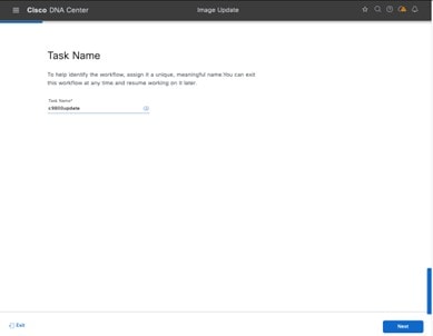
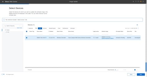
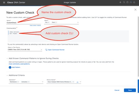
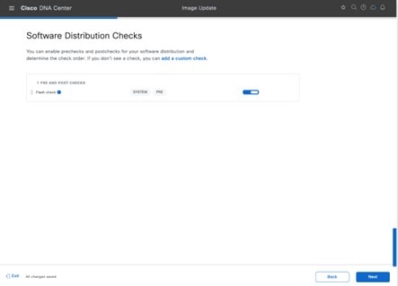
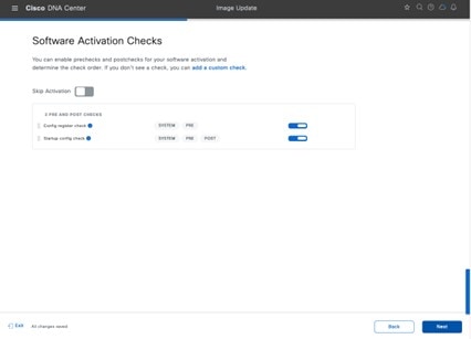
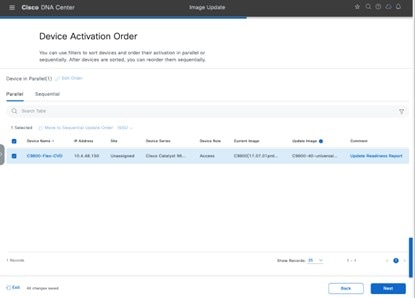
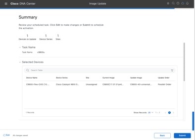
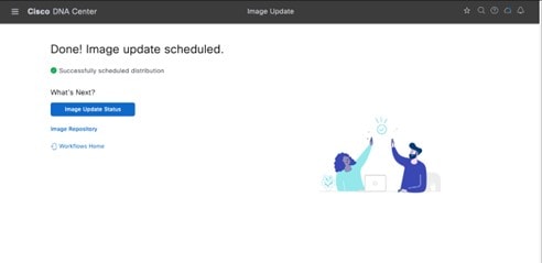
Configure HA SSO on the Cisco Catalyst 9800-40 Enterprise Wireless Controllers
Cisco Catalyst 9800 Series Wireless Controllers support the ability to be configured in an active or standby high availability (HA) stateful switch-over (SSO) pair. Cisco DNA Center supports the ability to take two controllers of the same model, running the same operating system version, and configure them as an HA SSO pair.
Note |
|
The following steps explain how to configure the Catalyst 9800-40 Wireless Controllers (WLC-9800-1 and WLC-9800-2) as an HA SSO pair.
Procedure
|
Step 1 |
From the top-left corner, click the menu icon and choose . The main provisioning window displays the devices. By default, the Focus is set for Inventory. |
||||||||||||||
|
Step 2 |
Locate and check the check box for the Catalyst 9800-40 Wireless Controller which will be the primary wireless controller of the HA SSO wireless controller pair. For this design and deployment guide, WLC-9800-2 was selected as the primary wireless controller. |
||||||||||||||
|
Step 3 |
From the Actions drop-down list, select . The High Availability slide-in pane is displayed. 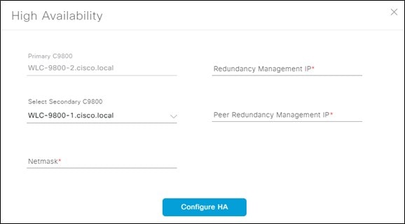
|
||||||||||||||
|
Step 4 |
Enter the required information in the respective fields and click Configure HA. The following table shows the high availability information for this deployment guide:
A dialog box is displayed, notifying you that the wireless controllers will be rebooted when they are placed in the high availability mode. |
||||||||||||||
|
Step 5 |
Click OK to accept and put the two Catalyst 9800-40 Wireless Controllers in HA SSO mode. It will take several minutes for the wireless controllers to reboot and display in HA SSO mode. All configurations from the primary Catalyst 9800-40 Wireless Controller, including the IP address of the management interface, will be copied to the secondary Catalyst 9800-40 Wireless Controller. Cisco DNA Center will no longer show two wireless controllers in the inventory. Instead, only a single Wireless Controller HA SSO pair with two serial numbers will appear in the inventory. For this deployment guide, the wireless controller HA SSO pair is WLC-9800-2. |
||||||||||||||
|
Step 6 |
If you choose the wireless controller (WLC-9800-2), and from the Actions drop-down list, choose , you can see additional information about the Catalyst 9800-40 Wireless Controller HA SSO pair. 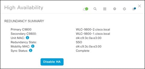
|
Provision the Cisco Catalyst 9800-40 Enterprise Wireless Controller HA SSO Pair
The following steps explain how to provision the corporate wireless profile to the Cisco Catalyst 9800-40 enterprise Wireless Controller HA SSO pair, known as Cisco Catalyst 9800-40-CVD.cagelab.local.
Procedure
|
Step 1 |
From the top-left corner, click the menu icon and choose . The main provisioning window displays the devices in the inventory. By default, Inventory is chosen from the Focus drop-down list. |
||||||||||||||||||||||||||||||||
|
Step 2 |
Locate and check the check box for C9800-40-CVD.cagelab.local. |
||||||||||||||||||||||||||||||||
|
Step 3 |
From the Actions drop-down list, choose . You are taken through a four-step workflow for provisioning the enterprise wireless controller HA SSO pair (C9800-40-CVD.cagelab.local), starting with Assign Site. |
||||||||||||||||||||||||||||||||
|
Step 4 |
In the Assign Site window, click Choose a Site. A slide-in pane is displayed, which shows the site hierarchy configured for Cisco DNA Center. For this deployment guide, the enterprise wireless controller HA SSO pair (C9800-40-CVD.cagelab.local) is assigned to the building level. |
||||||||||||||||||||||||||||||||
|
Step 5 |
Expand the site hierarchy for Milpitas and choose Building 23. 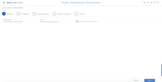
|
||||||||||||||||||||||||||||||||
|
Step 6 |
Click Save to assign C9800-40-CVD.cagelab.local to Building 23. |
||||||||||||||||||||||||||||||||
|
Step 7 |
Click Next. The Configuration window is displayed. |
||||||||||||||||||||||||||||||||
|
Step 8 |
In the Configuration window, choose Active Main for the wireless controller Role. |
||||||||||||||||||||||||||||||||
|
Step 9 |
Click Select Primary Managed AP locations. The Managed AP Location slide-in pane is displayed, showing the site hierarchy for Cisco DNA Center. 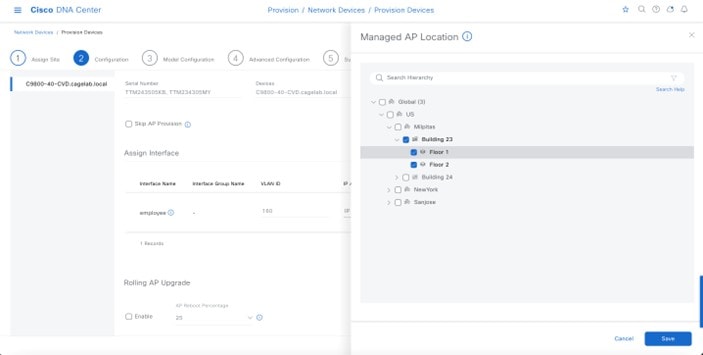
Cisco DNA Center supports the ability to configure N+1 redundancy for APs and HA SSO for a wireless controller. As a result, you can configure both primary and secondary managed AP locations. Primary managed AP locations are sites that include buildings and/or floors, where the wireless controller will serve as the primary wireless controller within the AP high availability configuration. Secondary managed AP locations are sites where the wireless controller will serve as the secondary wireless controller within the AP high availability configuration. If the primary wireless controller or wireless controller HA SSO pair fail, APs will reestablish CAPWAP connections to the wireless controller. For this guide, the Catalyst 9800-40 Wireless Controller HA SSO pair (C9800-40-CVD.cagelab.local) will be the primary wireless controller, managing APs on Floors 1 and Floor 2 of Building 23 and Building 24. No secondary managed AP locations will be configured because the wireless controller HA SSO pair already provides redundancy in a campus network, where all the APs are operating in a centralized mode deployment. |
||||||||||||||||||||||||||||||||
|
Step 10 |
Expand the site hierarchy and choose Floors 1 and Floor 2 for Building 23 and Floors 1 and Floor 2 for Building 24. |
||||||||||||||||||||||||||||||||
|
Step 11 |
Click Save. Because you have selected this wireless controller to be an Active Main wireless controller, additional fields are displayed. The corporate wireless profile has defined the enterprise SSID as lab3employee and the wireless interface on which the SSID terminates as employee on VLAN ID 160, so this enterprise SSID and wireless interface will be automatically displayed. Likewise, because the corporate wireless profile has defined the guest SSID as lab3guest and the wireless interface on which the SSID terminates as guest-dmz on VLAN ID 125, this information will also be automatically displayed. |
||||||||||||||||||||||||||||||||
|
Step 12 |
Enter the values for IP address, Gateway IP address, LAG/Port Number, and Subnet Mask (in bits) for each SSID. The following table shows the values entered for this deployment guide.
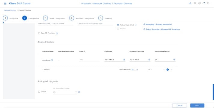
|
||||||||||||||||||||||||||||||||
|
Step 13 |
Click Next. The Advanced Configuration window is displayed. If you have configured a template within the Template Editor for the device type and the site, you can apply the template here. This deployment guide does not discuss the use of templates for advanced configuration of the Catalyst 9800-40 wireless controller HA SSO pair (C9800-40-CVD.cagelab.local). |
||||||||||||||||||||||||||||||||
|
Step 14 |
Click Next. The Summary window is displayed. This window provides a summary of the configuration which will be provisioned to the Catalyst 9800-40 Wireless Controller HA SSO pair (WLC-9800-2). You can expand each section to see the details of the configuration, which is based on the corporate wireless profile created in the Design the wireless network section of this deployment guide. 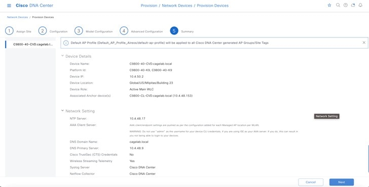
|
||||||||||||||||||||||||||||||||
|
Step 15 |
Click Deploy to deploy the configuration to the Catalyst 9800-40 Wireless Controller HA SSO pair (C9800-40-CVD.cagelab.local). A slide-in pane is displayed, asking if you wish to deploy the configuration now or schedule the configuration for later.
|
||||||||||||||||||||||||||||||||
|
Step 16 |
Click the Now radio button and click Apply to apply the configuration. You will be redirected to the Inventory window in Provisioning. The provisioning status of the device will temporarily show Provisioning, but the status should change to Success after a few minutes. Click See Details below the provisioning status of the device for more information. Cisco DNA Center will dynamically create two new WLAN profiles within the Catalyst 9800-40 enterprise Wireless Controller HA SSO pair (C9800-40-CVD.cagelab.local). Each WLAN profile has a dynamically generated name based on the SSID name specified in the corporate wireless profile. The following table shows the names of the WLAN profiles and their respective SSIDs, automatically generated by Cisco DNA Center during the provisioning of C9800-40-CVD.cagelab.local for this deployment guide.
An example of the WLAN configuration, as seen from the web-based GUI of C9800-40-CVD.cagelab.local is shown in the following figure. 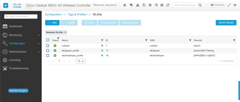
The WLAN IDs corresponding to the two SSIDs, lab3guest and lab3employee, are 17 and 18, respectively. When APs are assigned the policy tag default-policy-tag, APs joined to Cisco Catalyst 9800 Series Wireless Controller will broadcast SSIDs of WLANs with IDs from 1 to 16. In order to avoid creating WLAN IDs which are broadcast with the default-policy-tag, Cisco DNA Center creates WLANs and SSIDs starting with a WLAN ID of 17 and higher. During provisioning, Cisco DNA Center also creates two new policy profiles within the C9800-40-CVD.cagelab.local. The names of the new policy profiles match the names of the created WLAN profiles. An example of the configuration, as seen
from the web-based GUI of C9800-40-CVD.cagelab.local is shown in the following figure.
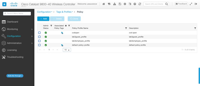
At this point in the provisioning process, the policy profiles and the WLAN profiles are not mapped to any policy tag that has been applied to any AP. |
Provision the Cisco Catalyst 9800-CL Guest Anchor Wireless Controller
Use the following procedure to provision the corporate wireless profile to the Cisco Catalyst 9800-CL guest anchor Wireless Controller, known as C9800-CL-CVD.cagelab.local.
Procedure
|
Step 1 |
From the top-left corner, click the menu icon and choose . The main provisioning screen displays the devices in the inventory. By default, Inventory is chosen from the Focus drop-down list. |
||||||||||||||||
|
Step 2 |
Locate and check the check box for C9800-CL-CVD.cagelab.local. |
||||||||||||||||
|
Step 3 |
From the Actions drop-down list, choose . You are taken through a four-step workflow for provisioning the guest wireless controller (C9800-CL-CVD), starting with Assign Site. |
||||||||||||||||
|
Step 4 |
In the Assign Site window, click Choose a Site. A slide-in pane is displayed, showing the site hierarchy configured for Cisco DNA Center. For this deployment guide, the guest anchor wireless controller (C9800-CL-CVD.cagelab.local) is assigned to the building level. |
||||||||||||||||
|
Step 5 |
Expand the site hierarchy for Milpitas and select Building 23. 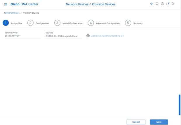
|
||||||||||||||||
|
Step 6 |
Click Save to assign C9800-CL-CVD.cagelab.local to Building 23. |
||||||||||||||||
|
Step 7 |
Click Next. The Configuration window is displayed. |
||||||||||||||||
|
Step 8 |
In the Configuration window, choose Guest Anchor for the wireless controller Role. |
||||||||||||||||
|
Step 9 |
Click Select Primary Managed AP locations. The Managed AP Location slide-in pane is displayed, showing the site hierarchy for Cisco DNA Center. 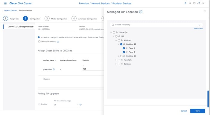
For this deployment guide, the guest anchor wireless controller (C9800-Flex-CVD.cagelab.local) will manage APs on Floor 1, Floor 2, and Floor 3 in building branch5. |
||||||||||||||||
|
Step 10 |
Expand the site hierarchy and choose the desired sites within the site hierarchy. |
||||||||||||||||
|
Step 11 |
Click Save. The Managed AP Location slide-in pane will close. Because you have selected this wireless controller to be a Guest wireless controller, additional fields are displayed. The corporate wireless profile has defined the enterprise SSID as lab3guest and the wireless interface on which the SSID terminates as branchguest-dmz on VLAN ID 110, so this enterprise SSID and wireless interface will be automatically displayed. |
||||||||||||||||
|
Step 12 |
Enter the values for IP address, Gateway IP address, LAG/Port Number, and Subnet Mask (in bits) for the SSID. The following table shows the values entered for this deployment guide.
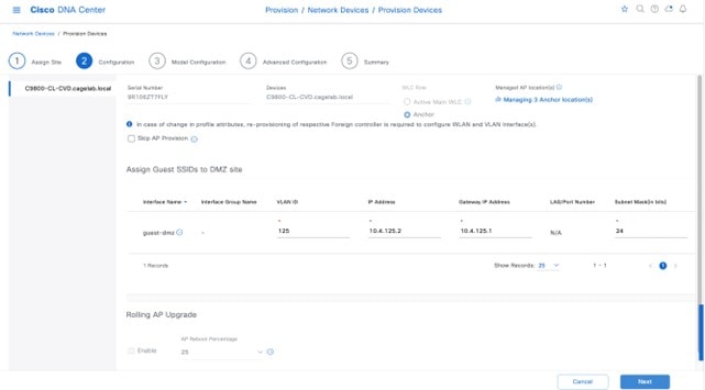
|
||||||||||||||||
|
Step 13 |
Click Next. The Model Configuration window is displayed. If you have configured a template within the model configs for the device type and the site, you can apply the template here, and you can edit and view the model configuration. In the campus wireless deployment, no model config is used. |
||||||||||||||||
|
Step 14 |
Click Next. The Summary window is displayed. 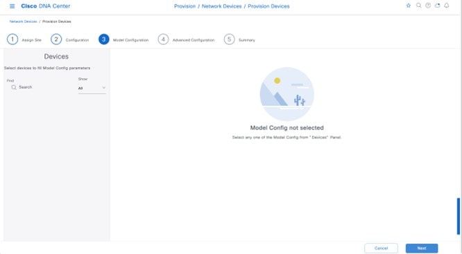
|
||||||||||||||||
|
Step 15 |
Click Next in the device provisioning workflow. The Advanced Configuration window is displayed. If you have configured a template within the Template Editor for the device type and the site, you can apply the template here. This deployment guide does not discuss the use of templates for advanced configuration of the Catalyst 9800-CL guest Wireless Controller. |
||||||||||||||||
|
Step 16 |
Click Next in the device provisioning workflow. The Summary window is displayed. This screen provides a summary of the configuration which is provisioned to C9800-CL-CVD. 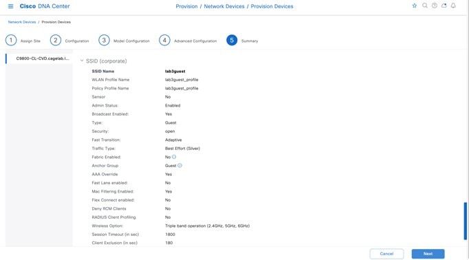
|
||||||||||||||||
|
Step 17 |
You can expand each section to see the details of the configuration, which is based on the corporate wireless profile created in the Design the wireless network section of this deployment guide. |
||||||||||||||||
|
Step 18 |
Click Next to deploy the configuration to C9800-CL-CVD. A slide-in pane is displayed, asking if you want to deploy the configuration now or schedule the configuration for later.
|
||||||||||||||||
|
Step 19 |
Click the Now radio button, and click Apply to apply the configuration. You will be redirected back to the Inventory window within Provisioning. The provisioning status of the device will temporarily show Provisioning, but the status will change to Success after a few minutes. Click See Details below the provisioning status of the device for more information. Cisco DNA Center will dynamically create a new WLAN profile within the Catalyst 9800-CL guest Wireless Controller (C9800-CL-CVD.cagelab.local). The following table shows the name of the WLAN profile and respective SSID generated by Cisco DNA Center during the provisioning of C9800-CL-CVD.cagelab.local for this deployment guide.
The WLAN profile name is based on the SSID name, specified within the corporate wireless profile and created during the Design the wireless network section of this deployment guide. An example of the WLAN configuration, as seen from the web-based GUI of C9800-CL-CVD.cagelab.local, is shown in the following figure.
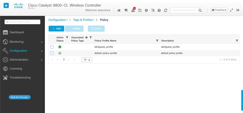
The WLAN ID corresponding to the lab3guest SSID is 17. When APs are assigned the policy tag default-policy-tag, the APs joined to Cisco Catalyst 9800 Series Wireless Controller will broadcast SSIDs of WLANs that have IDs from 1 to 16. To avoid creating WLAN IDs which are broadcast with the default-policy-tag, Cisco DNA Center creates WLANs or SSIDs starting with a WLAN ID of 17 and higher. During provisioning, Cisco DNA Center also creates a new policy profile within the C9800-40-CVD.cagelab.local. The name of the new policy profile matches the name of the created WLAN profiles. An example of the configuration, as seen from the web-based GUI of C9800-40-CVD.cagelab.local, is shown in the following figure. 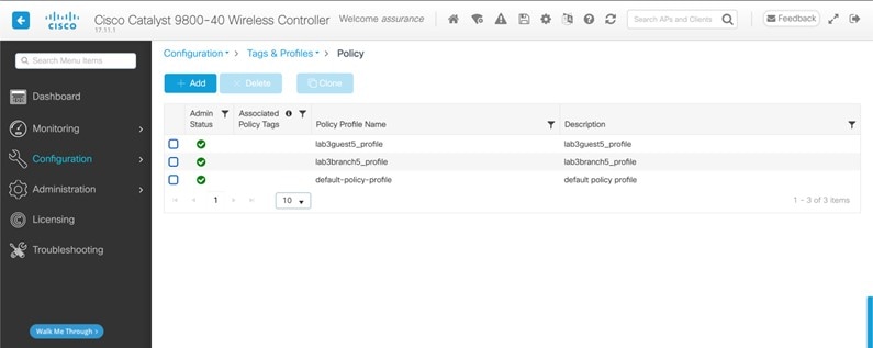
Cisco DNA Center will provision the mobility tunnel between the enterprise wireless controller HA SSO pair (C9800-40-CVD.cagelab.local) that functions as the foreign controller and the guest wireless controller (C9800-CL-CVD.cagelab.local) that functions as the anchor controller. The mobility tunnel is shown in the following figures. 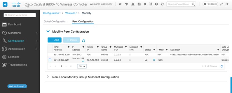
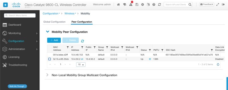
|
||||||||||||||||
|
Step 20 |
Click the lab3guest_Profile policy profile in the foreign controller (C9800-40-CVD.cagelab.local) and navigate to the Mobility window, which displays the mapping of the anchor controller to the policy profile. These settings are automatically configured by Cisco DNA Center during provisioning. 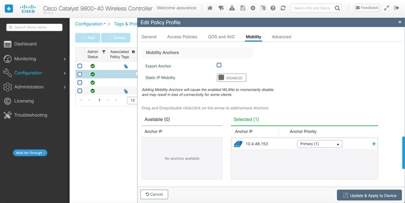
|
||||||||||||||||
|
Step 21 |
Click the lab3guest_profile policy profile in the anchor controller (C9800-CL-CVD.cagelab.local) and navigate to the Mobility window, which displays the export of the anchor controller within the policy profile (similar to the configuration of the anchor and foreign controllers within the Cisco AireOS Wireless Controllers). These settings are automatically configured by Cisco DNA Center during provisioning. 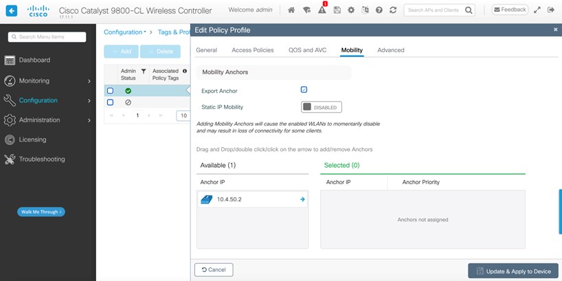
|
Join New APs to the Enterprise Cisco Catalyst 9800 Series Wireless Controller
The following steps explain how to discover and join the APs to the enterprise Catalyst 9800 Series Wireless Controller.
Before you begin
For this procedure in the deployment guide, assume that new APs will use IP DHCP discovery to discover the Cisco Catalyst 9800 Series Wireless Controller. Also assume that the new APs have never been primed. A Cisco AP has been primed when it has previously joined (established a CAPWAP tunnel) a wireless controller and cached the IP address of the wireless controller in NVRAM; or when primary, secondary, or tertiary wireless controller management IP addresses have been configured within the AP. In such scenarios, the AP will give preference to the primary, secondary, or tertiary wireless controller configuration over IP DHCP discovery.
With IP DHCP discovery, DHCP servers use Option 43 to provide one or more wireless controller management IP addresses to the APs. When an AP learns the management IP address of the Catalyst 9800 Series Wireless Controller, the AP sends a CAPWAP join request message to the wireless controller. Once joined, the wireless controller manages the APs configuration, firmware, control transactions, and data transactions.
Procedure
|
Step 1 |
Configure the necessary VLANs on the Layer 2 access switches that support the Cisco APs joining the Catalyst 9800 Series Wireless Controller. This deployment guide assumes that APs are connected to Layer 2 access switches. A dedicated VLAN is on the switches for APs that are separate from end-user devices, such as PCs and IP phones. The use of a dedicated VLAN for APs and switch management is generally regarded as a design best practice, but this method does result in additional VLANs being deployed on the switches. The management VLAN (VLAN 64) is used for establishing CAPWAP tunnels to branch APs and for managing connectivity to the branch switch. The branch employee VLAN (VLAN 16) is used for locally terminating wireless traffic from the corporate event SSID on the branch switch. |
|
Step 2 |
Configure VLAN 64 and VLAN 16 on the branch switch. |
|
Step 3 |
Configure the switch port to which the AP is connected to be a trunk port, with VLANs 64 and 16 allowed and VLAN 16 as the native VLAN. Make sure the switch port is not shut down. An example is shown in the following configuration. For this deployment guide, a Microsoft Active Directory (AD) server with IP address The following example depicts the configuration of a Layer 3 switch using a VLAN switched virtual interface (SVI): |
|
Step 4 |
Connect the Cisco AP(s) to the switch port(s) on the Layer 2 access switches. The APs should get IP addresses and automatically join the Catalyst 9800 Series Wireless Controller. Once the new APs register with the wireless controller, a resync on Cisco DNA Center is automatically triggered. After the resync is complete, the new APs will show up in the inventory. Alternatively, you can manually resync the inventory for the wireless controller using the following steps:
After you have resynced the Catalyst 9800-40 wireless controller HA SSO pair (WLC-9800-2), the APs that are joined to the wireless controller should appear within the inventory. |
Provision the New APs
Once the access points (APs) have been joined to the Cisco Catalyst 9800-40 enterprise Wireless Controller HA SSO pair (C9800-40-CVD.cagelab.local), the APs must be provisioned. Provisioning with Cisco DNA Center is necessary for the APs to receive the correct configuration to advertise the lab3employee and lab3guest SSIDs.
The following table lists the APs that are provisioned in this deployment guide, including their locations:
| AP Name | AP Model | Location |
|---|---|---|
|
mil23-floor1-ap1 |
C9130AXI-B |
Building 23, Floor 1 |
|
mil23-floor1-ap2 |
C9130AXI-B |
Building 23, Floor 1 |
|
mil23-floor2-ap1 |
C9130AXI-B |
Building 23, Floor 2 |
|
mil24-floor1-ap1 |
C9124AXD-B |
Building 24, Floor 1 |
|
mil24-floor2-ap1 |
C9124AXD-B |
Building 24, Floor 2 |
|
AP1416.9D7C.16FC |
C9130AXI-B |
Branch 5, Floor 1 |
|
AP1416.9D7C.16F8 |
C9130AXI-B |
Branch 5, Floor 2 |
Note |
In this deployment guide, a mixture of APs deployed across the buildings and floors shows the provisioning of different AP models in different locations, all controlled by the same Catalyst 9800 Series HA SSO Wireless Controller pair. In a typical deployment, the same AP model would be deployed for a floor and across the entire deployment. |
Procedure
|
Step 1 |
From the top-left corner, click the menu icon and choose . The main provisioning screen displays the devices within the inventory. By default, the Focus will be set for Inventory. |
||||||||||||||||||||||||
|
Step 2 |
Check the box for each of the APs to be provisioned. |
||||||||||||||||||||||||
|
Step 3 |
From the Actions drop-down menu, choose . You are taken through a workflow for provisioning the APs, starting Assign Site. |
||||||||||||||||||||||||
|
Step 4 |
For each of the APs, click Choose a Site. A side panel is displayed, showing the site hierarchy configured for Cisco DNA Center. Expand the site hierarchy for Milpitas, and then choose the building (Building 23 or Building 24) and the floor (Floor 1 or Floor 2) for each AP. 
|
||||||||||||||||||||||||
|
Step 5 |
Click Save. |
||||||||||||||||||||||||
|
Step 6 |
Click Next to set up the configuration. |
||||||||||||||||||||||||
|
Step 7 |
From the drop-down menu, for RF Profile, choose the RF profile that you want to assign to each of the APs. For this deployment guide, the TYPICAL RF profile was chosen. This RF profile was also chosen as the default RF profile in Design the wireless network. 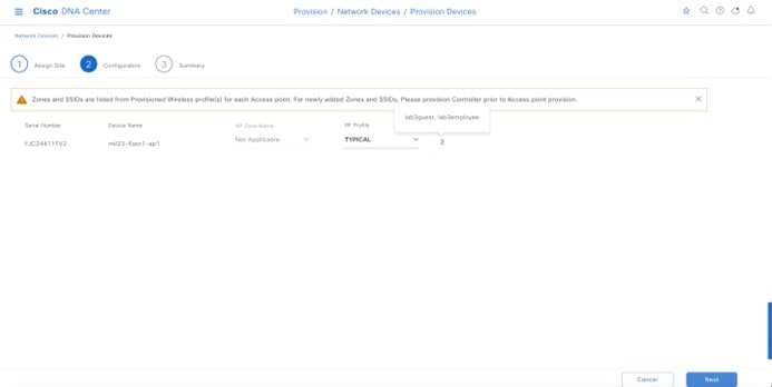
|
||||||||||||||||||||||||
|
Step 8 |
Click Next. The Summary screen is displayed with details of the configuration that will be provisioned to each AP. 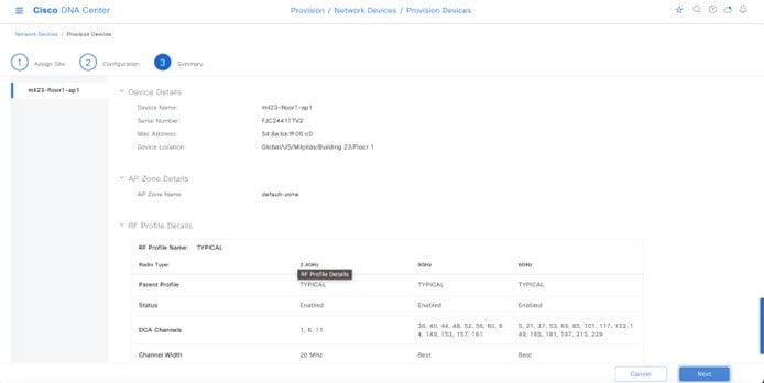
|
||||||||||||||||||||||||
|
Step 9 |
Click Deploy to provision the APs. A slide-in pane is displayed. You can choose to deploy the configuration now, or you can schedule the configuration for later. The best practice is to make configuration changes and provision new devices in your network only during scheduled network operation change windows. The following metrics describe the recommended scale limits. Outside of these recommended numbers, the wireless controller will work, but the controller will operate below its optimal performance.
|
||||||||||||||||||||||||
|
Step 10 |
Choose Now and then click Apply to apply the configuration. The Success dialog box is displayed, indicating that after provisioning, the APs will reboot. |
||||||||||||||||||||||||
|
Step 11 |
Click OK. The main Provisioning window displays the list of inventories. The provisioning status of the APs will temporarily show as Provisioning, but the status will transition to Success after a few minutes. For more information, you can click See Details directly below the provisioning status of each AP. |
Cisco DNA Center creates a new policy tag within the Catalyst 9800-40 enterprise Wireless Controller HA SSO pair (C9800-40-CVD.cagelab.local) for each floor that contains provisioned APs.
For example, in the following figure, three new policy tags are created, corresponding to the APs provisioned on Floor 1 of Building 23. Each policy tag is unique to a site, indicating a specific floor in a building. Policy tags for a floor will be created by Cisco DNA Center when APs are provisioned to the floor.
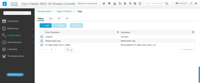
Click on any of the policy tags to display the policy profiles and the WLAN profiles that have been added to the new policy tag by Cisco DNA Center.
The WLAN profiles and the policy profiles created during the provisioning of the Catalyst 9800-40 enterprise Wireless Controller HA SSO pair have been added to each of the policy tags, which are controlled by the corporate WLAN profile created in Cisco DNA Center in Design the wireless network. The corporate WLAN profile specified the lab3employee and lab3guest SSIDs to be broadcast throughout the Milpitas area (Floor 1 in Buildings 23).
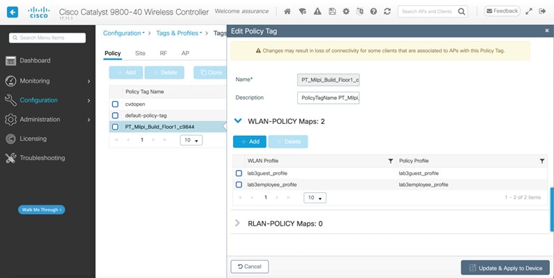
During the AP provisioning process, the TYPICAL RF profile was chosen. Cisco DNA Center creates a new RF tag named TYPICAL within the Catalyst 9800-40 enterprise Wireless Controller HA SSO pair (WLC-9800-2).
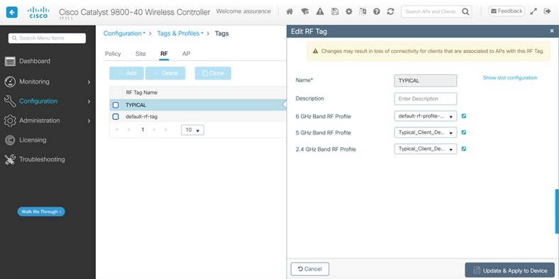
Finally, Cisco DNA Center statically assigns a policy tag (specific to each floor), an RF tag (named TYPICAL since this was the only RF Profile specified during AP provisioning), and a site tag (named ST_Milpi_Building_e3b46_0) to each AP within the Catalyst 9800-40 enterprise wireless controller HA SSO pair (C9800-40-CVD.cagelab.local). The site tag ST_Milpi_Building_e3b46_0 contains the default AP join profile named default-ap-profile.
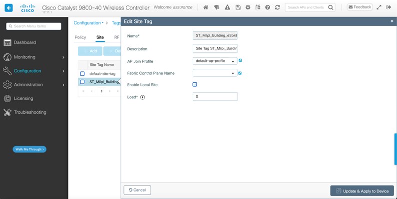
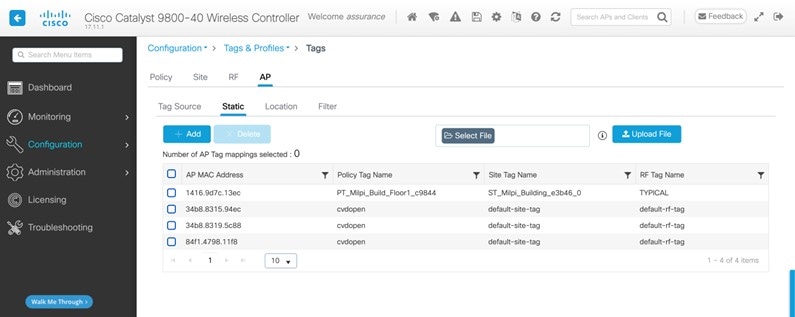
The assignment of the policy tag to the AP causes the lab3employee and lab3guest SSIDs to be broadcast by the AP provisioned on the floor. At this point, wireless clients should be able to associate with the lab3employee and/or lab3guest SSIDs and authenticate to the network.
Position New APs on a Floor Map with No Planned AP
You must position the newly discovered APs on the floor maps if there is no corresponding AP planned for each of the buildings and floors within Cisco DNA Center. When a planned AP matches the hostname of the new AP, the new AP is automatched with the planned AP and positioned as per the planned AP.
Note |
Automatching only happens when browsing to the floor in the network hierarchy. |
At this point in the deployment, the AP in local mode should be broadcasting the SSID on the floors for Milpitas, Building 23.
Procedure
|
Step 1 |
From the top-left corner, click the menu icon and choose . |
|
Step 2 |
Expand the network hierarchy in left hierarchy tree and choose Milpitas > Building 23 > Floor 1. The floor plan for Floor 1 is displayed. |
|
Step 3 |
Click Add/Edit to edit the floor plan. The unpositioned APs are displayed, allowing you to edit various aspects of the floor plan. 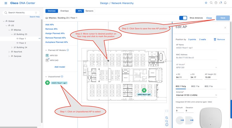
|
|
Step 4 |
Choose an unpositioned AP, move your cursor to the correct location on the floor map, and then click to choose the desired position. The floor map will change, showing additional details about the position of the AP on the floor map. You may need to select the antenna for the AP, depending on the model of AP that you are positioning. If you need to select the antenna, a red warning will be displayed. |
|
Step 5 |
(Optional) Click on the 802.11a/b/g/n tab to display the antenna, azimuth, and elevation settings. |
|
Step 6 |
From the Antenna drop-down list, choose the antenna type for the AP being positioned. For the design and deployment guide, internal antennas were used on all APs. |
|
Step 7 |
Repeat the Step 1 through Step 6 for the 802.11a tab. You can fine tune the position and adjust the AP height, once the AP is placed on the floor map. The default AP height will be based on the height of the floor that you specified when you imported the floor map. You can adjust the azimuth and elevation settings of the antennas, or for APs with integrated antennas, you can adjust the azimuth and elevation of the AP. |
|
Step 8 |
Repeat Step 1 through Step 7 for the remaining unpositioned APs on the floor. |
|
Step 9 |
Click Save. The positioning of the APs on the floor map is saved. Once you have positioned the APs on the floor map, you should see heat maps. By default, the heat maps display AP RSSI values, which provide a rough estimate of the coverage area of each of the APs on the floor. The heat maps can be displayed for 2.4 GHz coverage, 5 GHz coverage, or both 2.4 and 5 GHz coverage. |
|
Step 10 |
(Optional) Click Add/Edit again, to edit the floor plan. |
|
Step 11 |
In the Overlays section, you have the option to add coverage areas, openings, location regions, walls, shelving units, markers, GPS markers, and align points to make the floor plan more accurately reflect the RF characteristics of the actual floor. At this point in the deployment, the AP in local mode should be broadcasting the SSID on the floors for Milpitas, Building 23. |
Enterprise WLAN for Remote Office Wireless Deployment
This section describes how to provision an AP in flex mode for the New York site.
Use this procedure to provision the branch5 wireless profile to the Cisco Catalyst 9800-40 enterprise Wireless Controller (C9800-Flex-CVD). For information about the branch5 wireless profile, see Define the Wireless Network.
Before you begin
Make sure that the wireless controller has been discovered, the software image has been updated, and the high availability (HA) wireless controller has been configured.
Procedure
|
Step 1 |
From the top-left corner, click the menu icon and choose . The main provisioning window displays the devices. By default, the Focus will be set to Inventory. |
||||||||||||||||||||||||||||||
|
Step 2 |
Check the check box for the Cisco Catalyst 9800-40 enterprise Wireless Controller (C9800-Flex-CVD). |
||||||||||||||||||||||||||||||
|
Step 3 |
From the Actions drop-down menu, choose . You are taken through a workflow for provisioning the enterprise wireless controller (C9800-Flex-CVD), starting with Assign Site. |
||||||||||||||||||||||||||||||
|
Step 4 |
Click Choose a Site in the Assign Site window. A slide-in pane is displayed, showing the site hierarchy configured for Cisco DNA Center. The enterprise wireless controller (C9800-Flex-CVD) must be assigned at the building level. Do the following in the Choose a Site slide-in pane:
|
||||||||||||||||||||||||||||||
|
Step 5 |
Click Next. |
||||||||||||||||||||||||||||||
|
Step 6 |
In the Configuration window, do the following:
|
||||||||||||||||||||||||||||||
|
Step 7 |
The Model Configuration window is displayed. If you have configured a template within the Model configs for the device type and the site, you can apply the model config here, and you can edit and view the model config of the flex configuration. 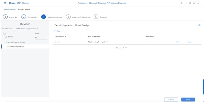
|
||||||||||||||||||||||||||||||
|
Step 8 |
Click Next. |
||||||||||||||||||||||||||||||
|
Step 9 |
The Advanced Configuration window is displayed. If you have configured a template in the window for the device type and for the site, you can apply the template here. This deployment guide does not discuss the use of templates for advanced configuration of the Catalyst 9800-40 Series Wireless Controller (C9800-Flex-CVD). |
||||||||||||||||||||||||||||||
|
Step 10 |
Click Next. |
||||||||||||||||||||||||||||||
|
Step 11 |
The Summary window is displayed. This window provides a summary of the configuration that will be provisioned to the Catalyst 9800-40 Series Wireless Controller (C9800-Flex-CVD). 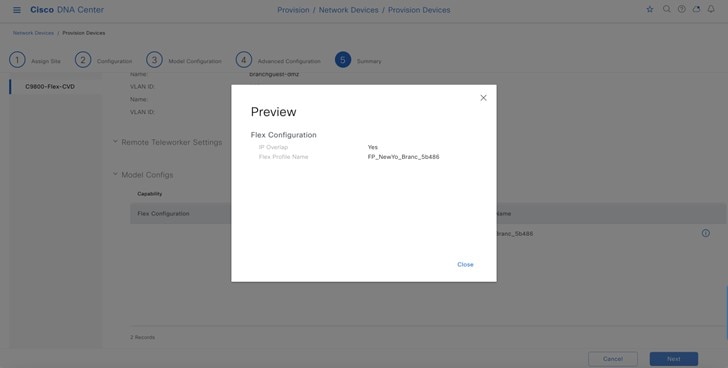
You can expand each area to see the details of the configuration. The configuration is based on the branch5 wireless profile created during the Design the wireless network section of this guide. |
||||||||||||||||||||||||||||||
|
Step 12 |
Click Deploy to deploy the configuration to the Catalyst 9800-40 Series Wireless Controller HA SSO pair (C9800-40-CVD.cagelab.local).
|
||||||||||||||||||||||||||||||
|
Step 13 |
Click Now to deploy the configuration immediately or click Later to schedule the deployment for a later time. |
||||||||||||||||||||||||||||||
|
Step 14 |
Click Apply. You will be taken back to the Inventory window within provisioning. After the devices are deployed successfully, the provision status changes from Provisioning to Success. |
||||||||||||||||||||||||||||||
|
Step 15 |
For more information, click See Details below the provisioning status of the device. Cisco DNA Center will dynamically create two new WLAN profiles within the Catalyst 9800-40 enterprise Wireless Controller HA SSO pair (C9800-Flex-CVD). Each WLAN profile has a dynamically generated name, based on the SSID name specified within the branch5 wireless profile and created during the Design the wireless network section of this deployment guide. The following table shows the names of the WLAN profiles and their respective SSIDs, automatically generated by Cisco DNA Center during the provisioning of C9800-40-CVD.cagelab.local for this deployment guide.
An example of the WLAN configuration in the web-based GUI of C9800-Flex-CVD.cagelab.local is shown in the following figure. 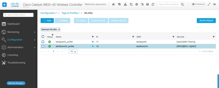
During provisioning, Cisco DNA Center also creates two new policy profiles within C9800-Flex-CVD. The names of new policy profiles match the names of the created WLAN profiles. An example of the configuration in the web-based GUI of C9800-Flex-CVD is shown in the following figure. 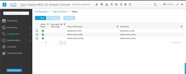
At this point in the provisioning process, the policy profiles and the WLAN profiles are not mapped to any policy tag that has been applied to any AP. On the controller, Cisco DNA Center creates flex profiles with names generated by Cisco DNA Center. 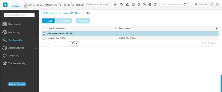
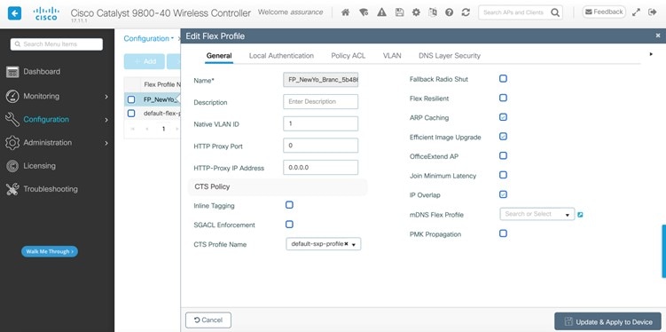
|
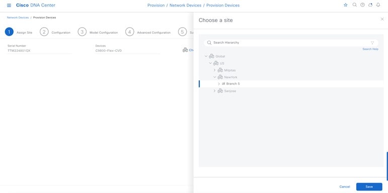
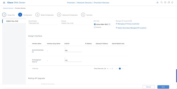
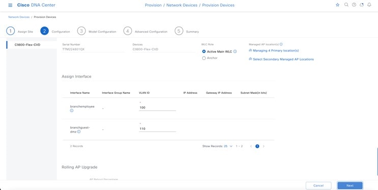
Provision an AP for the N+1 Wireless Controller
The following steps explain how to provision an AP associated with the N+1 wireless controller.
Procedure
|
Step 1 |
From the top-left corner, click the menu icon and choose . |
|
Step 2 |
Choose the desired AP, and from the Actions drop-down list, choose . |
|
Step 3 |
Choose Assign Site for the AP. 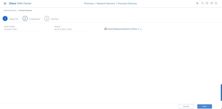
The Configuration window shows the SSID to be provisioned to the AP. 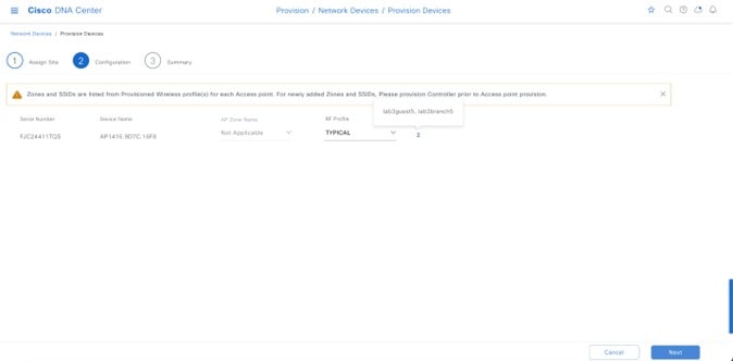
Cisco DNA Center shows the AP summary details before provisioning. 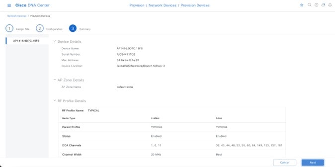
|
|
Step 4 |
Go to to view the provision status of the AP. 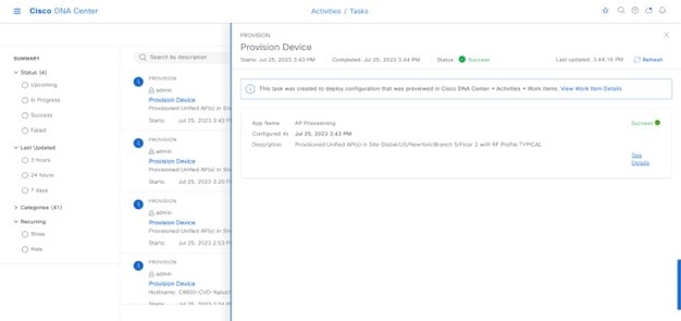
|
|
Step 5 |
After provisioning, check the AP configuration details. 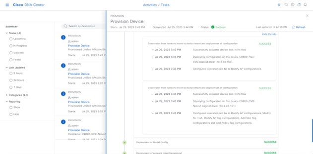
|
|
Step 6 |
Check the AP configuration on the wireless controller. The AP should correctly show high availability of the primary and secondary controllers. The AP joins the primary controller after the reboot, and the AP will be able to join the secondary controller if the primary controller is unreachable. Included in the N+1 controller provision and the AP-joined primary controller, the primary controller and the secondary controller details were changed in the high availability of the AP. 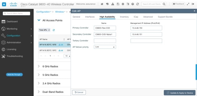
|
|
Step 7 |
Repeat the procedure to provision the second AP on Floor 2 of Branch 5 and verify that the primary and secondary wireless controllers are configured correctly, as shown in following figure. 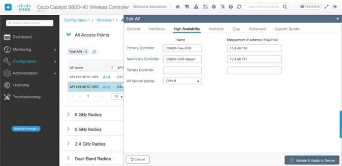
|
Configure the N+1 Wireless Controller for FlexConnect
For this guide, the Cisco Catalyst 9800-40 Wireless Controller is named Cisco Catalyst 9800-CVD-Nplus1.cagelab.local, serving as the N+1 controller (secondary controller) for Cisco Catalyst 9800-Flex-CVD.cagelab.local (primary controller).
Perform the following steps to deploy the N+1 controller, assuming the N+1 controller is present in the same site as the primary controller.
Procedure
|
Step 1 |
From the top-left corner, click the menu icon and choose and choose the N+1 controller. |
|
Step 2 |
From the Actions drop-down menu, choose . |
|
Step 3 |
In the Assign Site window, assign the site to N+1 controller and to the Branch 5 building location, as shown in the following figure. 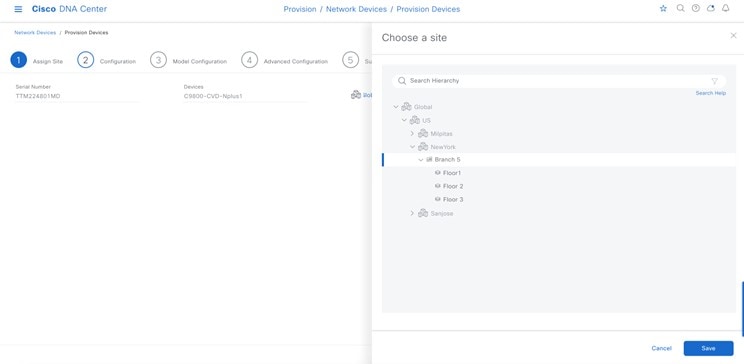
|
|
Step 4 |
In the Configuration window, click Managing Secondary Locations, which manages the primary controller AP. 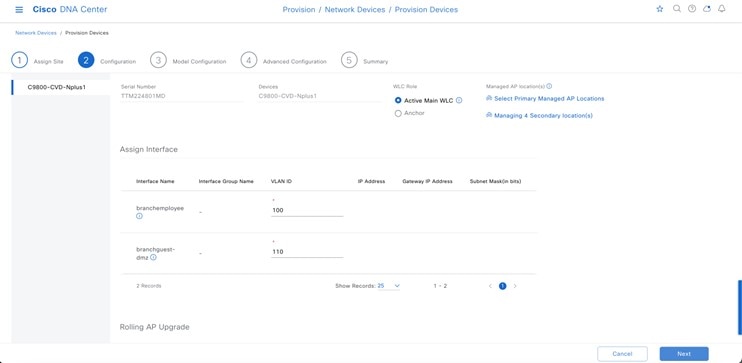
|
|
Step 5 |
Choose the floors managed by the primary controller. 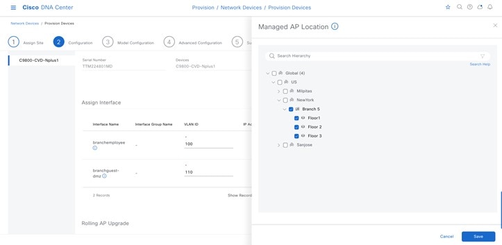
Cisco DNA Center will automatically recognize the model config with the flex configuration as a part of the primary controller. 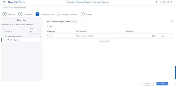
|
|
Step 6 |
In the Summary window, you can review the details of the SSID, sites, and network settings configuration before deployment. 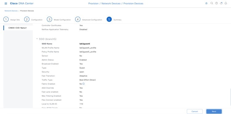
|
|
Step 7 |
Choose the Generate Configuration Preview radio button to review the configuration before deployment. 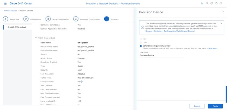
|
|
Step 8 |
Click Apply. |
|
Step 9 |
Choose . Cisco DNA Center should provision the controller successfully. Cisco DNA Center applies the same configurations from the primary controller to the N+1 controller. The following figures show the provision summary. 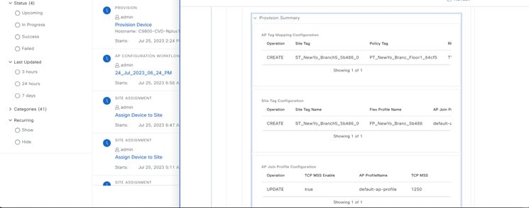
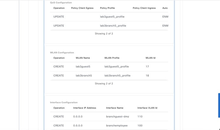
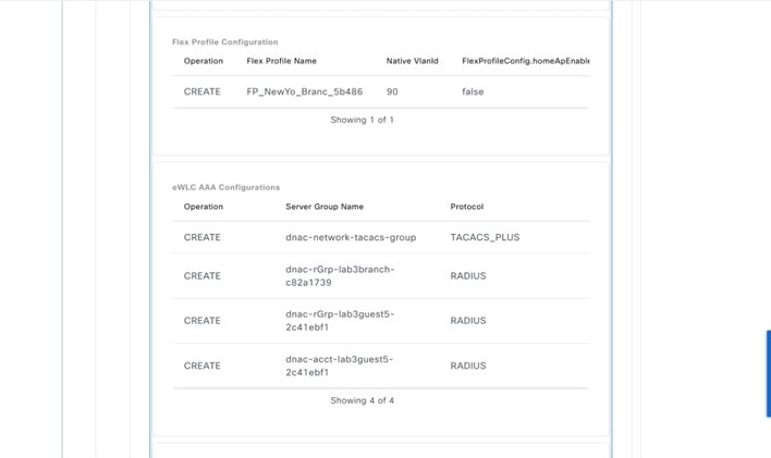
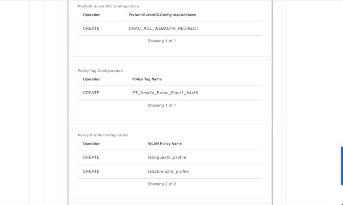
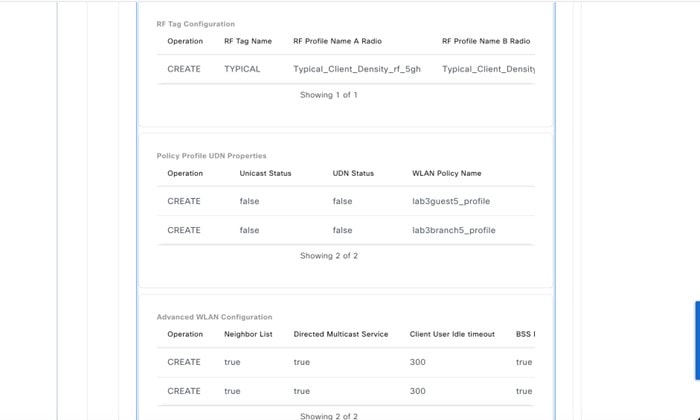
The following figure displays the flex configuration using a model config. 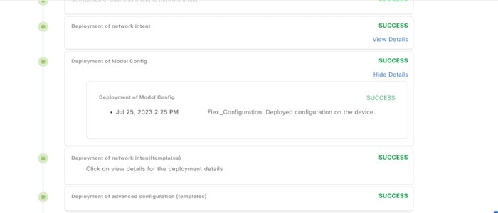
|
Create AP Zones for Onboarding Two SSIDs with Different Sets of APs on the Same Floor
An AP zone allows you to associate different SSIDs and RF profiles for a set of APs on the same site. You can use device tags to identify the APs for which you want to apply the AP zone. From the AP Zones tab within the wireless profile, you can create separate AP zones with a subset of SSIDs configured in the network profile for a device tag. Cisco DNA Center applies the AP zone configurations to APs during provisioning.
In this guide, two zones will be created in New York, building Branch 5, Floor 1. There will be two APs on the floor: one AP will be in zone1 broadcasting corporate SSID, and the other AP will be in zone2 broadcasting the guest SSID.
The following steps explain how to create two AP zones and provision the APs to be configured with these zones:
-
From the top-left corner, click the menu icon and choose and click Edit for the Corporate network profile.
Figure 130. AP Zone: Network Profile Window 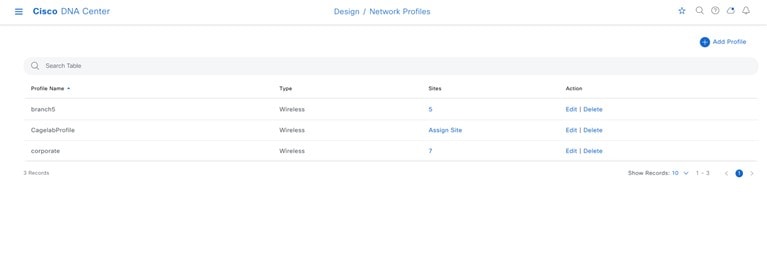
-
Click the AP Zones tab, and create two AP zones. Name the first zone sjcfloor1zone2 for lab3branch5 SSID with RF profiles: High, and name the other AP zone sjcfloor1zone1 for lab3guest5 SSID with RF Profiles: Low.
Figure 131. AP Zone1 Created Under Network Profile 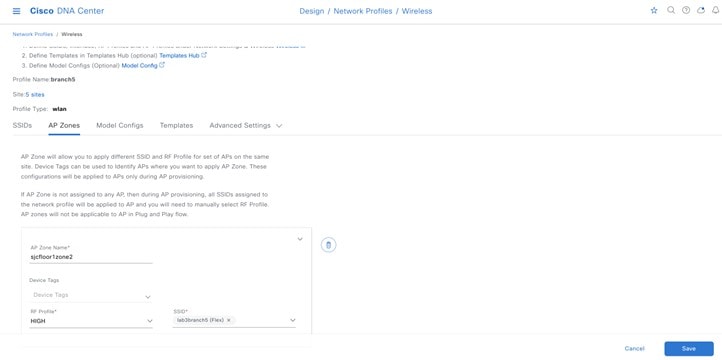
Figure 132. AP Zone2 Created Under Network Profile 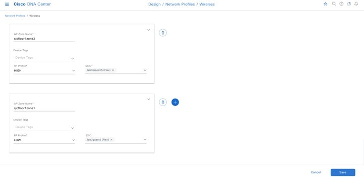
-
Click Save.
Note
Cisco DNA Center does not apply AP zone configurations to the APs claimed from the Plug and Play (PnP) process.
If an AP zone is already provisioned on an AP and if an AP zone configuration is later updated, the wireless controller must be reprovisioned to apply the updates. Reprovisioning the AP is not necessary.
During AP provisioning, based on the device tag and site of the AP, Cisco DNA Center chooses the corresponding AP zone and automatically assigns the RF profile. If two AP zones are configured for an AP, you can choose the required AP zone. If there are no AP zones for an AP, you can choose the required RF profile. Before creating an AP zone, ensure that you have created wireless SSIDs under the tab. To apply the AP zone configuration to an AP, reprovision the wireless controller.
Provision One AP to Zone Named sjcfloor1zone1 for lab3guest5 SSID with RF Profiles: Low
-
From the top-left corner, click the menu icon and choose .
-
Choose the AP and from the Actions drop-down menu, and choose .
-
Choose the site for the AP and click Next.
Figure 133. AP Zone Provision – Site Selection 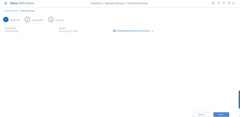
-
Choose the AP zone from the drop-down list.
Figure 134. AP Zone Provision – Zone Selection 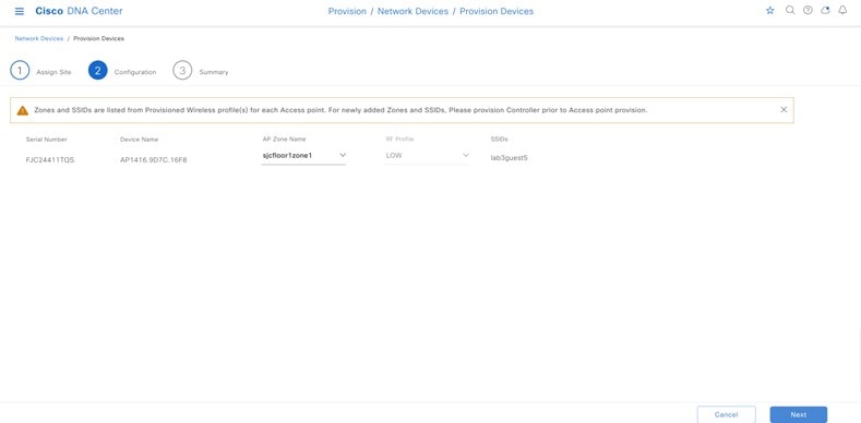
-
Review the details in the Summary window and click Next.
Figure 135. AP Zone Provision Summary 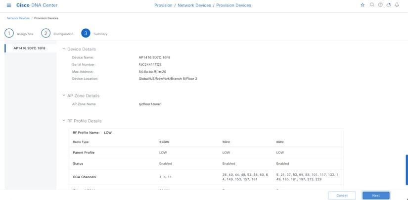
-
Go to and verify that the AP zone is successfully provisioned to the AP.
Figure 136. AP Zone Provision Status 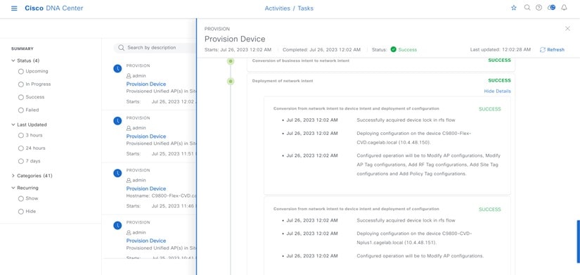
-
Check the AP configuration on the Cisco Wireless Controller GUI. The AP configuration shows RF tag, site tag, and policy tag correctly in the wireless controller.
Figure 137. AP1 SSIDs Provisioned through Cisco DNA Center 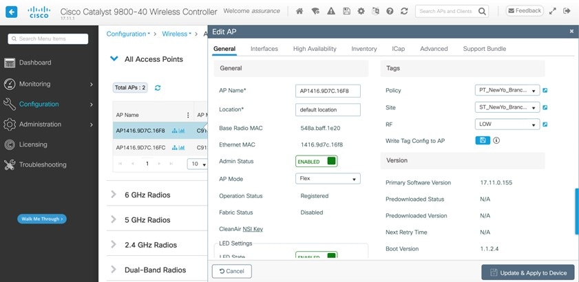
Figure 138. Policy Tag1 Provisioned through Cisco DNA Center 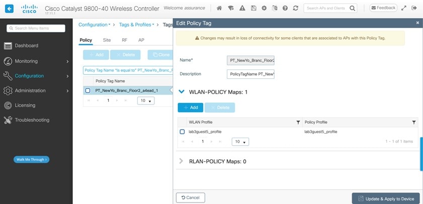
Figure 139. Site Tag1 Provisioned through Cisco DNA Center 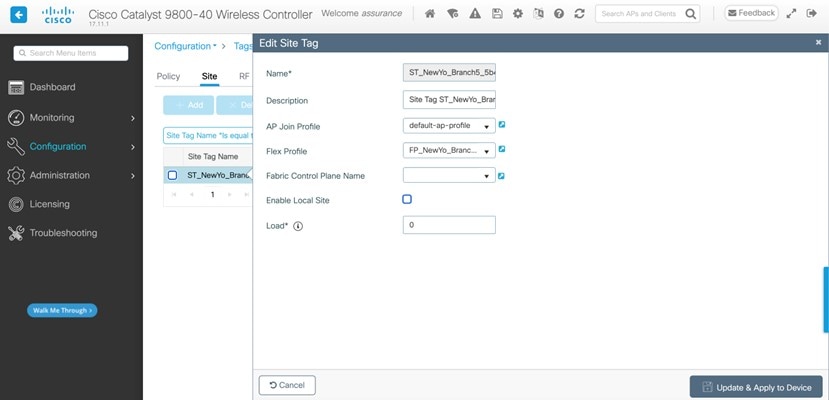
-
Repeat Step 1 through Step 7 to provision the AP named sjcfloor1zone2 for lab3branch5 SSID with RF Profiles: High.
-
Check the AP configuration for second AP in the wireless controller GUI. The AP configuration shows RF tag, site tag, and policy tag correctly in the controller.
Figure 140. AP2 SSIDs Provisioned through Cisco DNA Center 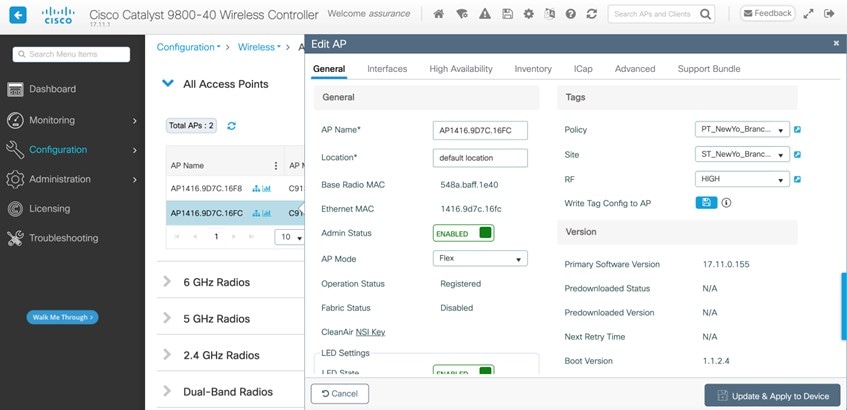
Figure 141. Policy Tag2 Provisioned through Cisco DNA Center 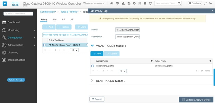
Figure 142. Site Tag2 Provisioned through Cisco DNA Center 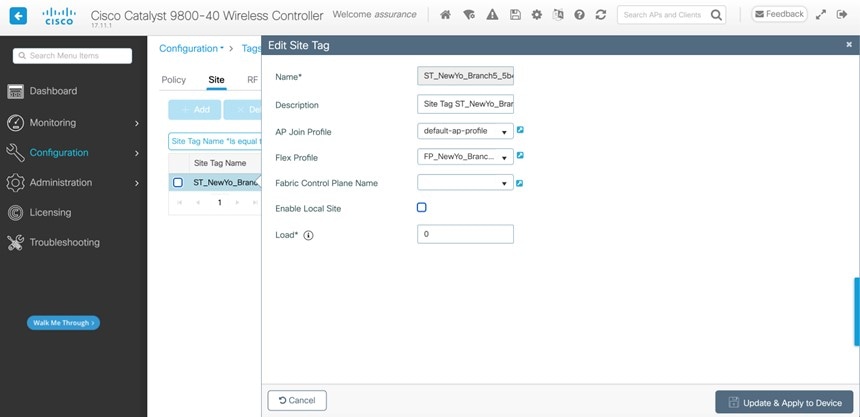
Join New APs to the Enterprise Cisco Catalyst 9800 Series Wireless Controller HA SSO Pair (WLC-9800-2)
This deployment guide assumes that new APs use IP DHCP Discovery to discover the Cisco Catalyst 9800-40 Wireless Controller HA SSO pair (WLC-9800-2) and that the new APs have never been primed. A Cisco AP has been primed when it has previously joined (established a CAPWAP tunnel) to a wireless controller and cached the IP address of the wireless controller in NVRAM; or when primary, secondary, or tertiary wireless controller management IP addresses have been configured within the AP. In such scenarios, the AP will give preference to the primary, secondary, or tertiary wireless controller configuration over IP DHCP Discovery.
With IP DHCP Discovery, DHCP servers use Option 43 to provide one or more wireless controller management IP addresses to the APs. When an AP learns the management IP address of the Catalyst 9800-40 Wireless Controller HA SSO pair (WLC-9800-2), it will send a CAPWAP join request message to the wireless controller. When joined, the wireless controller manages the APs configuration, firmware, control transactions, and data transactions.
The following steps explain how to discover and join the APs to the enterprise wireless controller HA SSO pair (WLC-9800-2).
Procedure
|
Step 1 |
Configure the necessary VLANs on the Layer 2 access switches that support the Cisco APs, which join the Catalyst 9800-40 enterprise Wireless Controller HA SSO pair (WLC-9800-2). This deployment guide assumes that APs are connected to Layer 2 access switches. A dedicated VLAN is on the switches for APs that are separate from end-user devices, such as PCs and IP phones. The use of a dedicated VLAN for APs is generally regarded as a design best practice, but this method does result in additional VLANs being deployed on the switches. The following example shows the configuration on a Layer 2 access switch: |
|
Step 2 |
Configure the switch ports to which the APs will be connected to be part of the configured VLAN. Ensure that the switch ports are not shut down. The following example shows the interface configuration: In a deployment scenario with Layer 2 access switches, the upstream Layer 3 device (switch or router), that is associated with the VLAN connected to the AP, must be configured to relay DHCP requests to a centralized DHCP server. The relay function is enabled through the ip helper-address interface-level command. |
|
Step 3 |
Configure the necessary DHCP relay commands on the upstream Layer 3 devices that support APs, which join the Catalyst 9800-40 enterprise Wireless Controller HA SSO pair (WLC-9800-2). The following example shows the configuration on a Layer 3 switch using a VLAN switched virtual interface (SVI): |
|
Step 4 |
Configure the DHCP scopes within the IP DHCP server to return the management IP address of the Catalyst 9800-40 enterprise Wireless Controller HA SSO pair (WLC-9800-2) in Option 43. For this deployment guide, a Microsoft Active Directory (AD) server with IP address 10.4.48.10 functions as the IP DHCP server. The IPv4 address of the enterprise wireless controller HA SSO pair (WLC-9800-2) configured within DHCP Option 43 is 10.4.74.32. Configuration of the DHCP within the Microsoft AD server is outside the scope of this document. |
|
Step 5 |
Connect the Cisco AP(s) to the switch port(s) on the Layer 2 access switches. The APs should get IP addresses and automatically join the Catalyst 9800-40 enterprise Wireless Controller HA SSO pair (WLC-9800-2). When the inventory resync interval for WLC-9800-2 passes, the new APs should be displayed in the Cisco DNA Center inventory. Alternatively, you can manually resync the inventory for the wireless controller using the following steps:
After you have resynced the Catalyst 9800-40 Wireless Controller HA SSO pair (WLC-9800-2), the APs that are joined to the wireless controller should be displayed in the Inventory window. |
Provision the New APs
Once the APs have been joined to the Cisco Catalyst 9800-40 enterprise Wireless Controller HA SSO pair (C9800-40-CVD.cagelab.local), they must be provisioned. Provisioning with Cisco DNA Center is necessary for the APs to receive the correct configuration to advertise the lab3employee and lab3guest SSIDs. The following table lists the APs that were provisioned for this deployment guide, including their locations.
| AP Name | AP Model | Location |
|---|---|---|
|
AP1416.9D7C.16FC |
C9130AXI-B |
Branch 5, Floor 1 |
Note |
The mixture of APs deployed across the buildings and floors within this design and deployment guide is simply to show the provisioning, through Cisco DNA Center, of different models of APs in different locations, all controlled by the same Catalyst 9800 Series HA SSO Wireless Controller pair. In a typical deployment, the same AP model would tend to be deployed within a floor, and often across the entire deployment. |
The following are the steps for provisioning APs within Cisco DNA Center.
Procedure
|
Step 1 |
From the top-left corner, click the menu icon and choose . The main provisioning window displays the devices. By default, the Focus will be set for Inventory. |
||
|
Step 2 |
Locate and check the check box for each of the APs to be provisioned. |
||
|
Step 3 |
From the Actions drop-down menu, choose . You are taken through a workflow for provisioning the APs, starting with Assign Site. |
||
|
Step 4 |
For each of the APs listed, click Choose a Site. A slide-in pane is displayed, showing the site hierarchy that is configured for Cisco DNA Center. |
||
|
Step 5 |
Expand the site hierarchy for New York, choose the building (Branch 5) and the floor (Floor 1) for each AP. 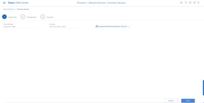
|
||
|
Step 6 |
Click Save to save the site assignments for the APs. |
||
|
Step 7 |
Click Next to advance to the next in the provisioning workflow, Configuration. |
||
|
Step 8 |
From the RF Profile drop-down list, choose the RF profile to assign to each of the APs. For this deployment guide, the TYPICAL RF profile was chosen. The TYPICAL RF profile was also chosen as the default RF profile in Design the wireless network. 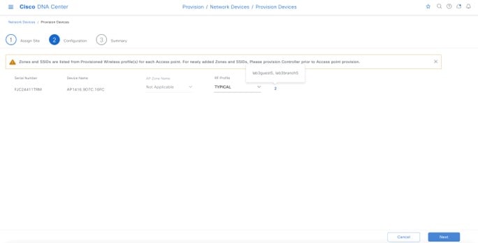
|
||
|
Step 9 |
Click Next to advance to the next step in the provisioning workflow, Summary. The Summary window provides a summary of the configuration that will be provisioned to each of the APs. 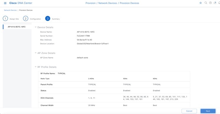
|
||
|
Step 10 |
Click Deploy to provision the APs. A slide-in pane is displayed. You can deploy the configuration now, or you can schedule the configuration to be deployed later.
|
||
|
Step 11 |
Click the Now radio button. |
||
|
Step 12 |
Click Apply to apply the configuration. A Success dialog box is displayed, with a message indicating that after provisioning, the APs will reboot, and the AP mode will change from local to flex. |
||
|
Step 13 |
Click OK to confirm. The list of inventories in the main provisioning window is displayed. The provisioning status of the APs will temporarily show Provisioning, but the status will change to Success after a few minutes. For more information, you can click See Details below the provisioning status of each AP. For each floor that contains the provisioned APs, Cisco DNA Center creates a new policy tag in the Catalyst 9800-40 enterprise Wireless Controller HA SSO pair (C9800-Flex-CVD). 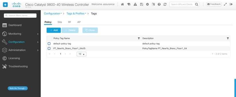
Three new policy tags have been created, corresponding to the APs provisioned on Floor 1 of building Branch 5. Each policy tag is unique to a site, indicating a specific floor within a building. Policy tags for a floor will only be created by Cisco DNA Center when APs are provisioned to the floor. By clicking on any of the policy tags, you can display the policy profiles and the WLAN profiles that are added to the new policy tag by Cisco DNA Center.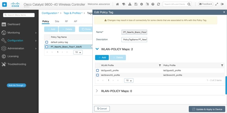
The WLAN profiles and the policy profiles that are created during the provisioning of the Catalyst 9800-40 enterprise Wireless Controller HA SSO pair have been added to each of the policy tags. This process is controlled by the branch5 WLAN profile that is created in Cisco DNA Center within Design the wireless network. The branch5 WLAN profile specified the lab3branch5 and lab3guest5 SSIDs to be broadcast throughout the New York area (Floor 1 of building Branch 5). During the AP provisioning process, the TYPICAL RF profile was chosen. Cisco DNA Center creates a new RF tag named TYPICAL within the Catalyst 9800-40 enterprise Wireless Controller HA SSO pair (C9800-Flex-CVD). 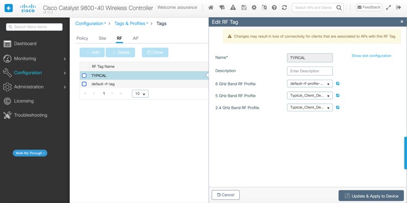
Finally, Cisco DNA Center statically assigns a policy tag (specific to each floor), the RF tag (named TYPICAL), and the site tag (named ST_NewYo_Branch5_5b486_0) to each AP in the Catalyst 9800-40 enterprise Wireless Controller HA SSO pair (C9800-Flex-CVD). The site tag ST_NewYo_Branch5_5b486_0 contains the default AP join profile named default-ap-profile. An example of the static assignment of the policy tag, site tag, and RF tag to each AP is shown in the following figure. 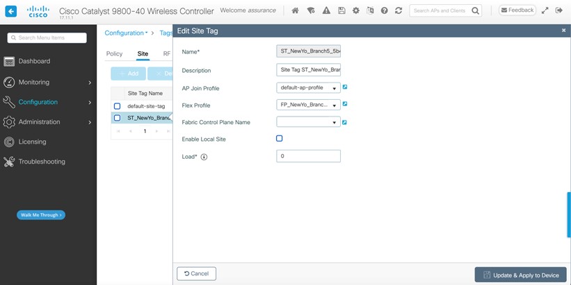
The flex profile was mapped to the site tag, with the local site being disabled. After the AP provision with VLAN 90, the flex profile was correctly updated with the native VLAN ID. 
To view the flex profile local VLAN mapped to the flex profiles, click the VLAN tab for the flex profile. 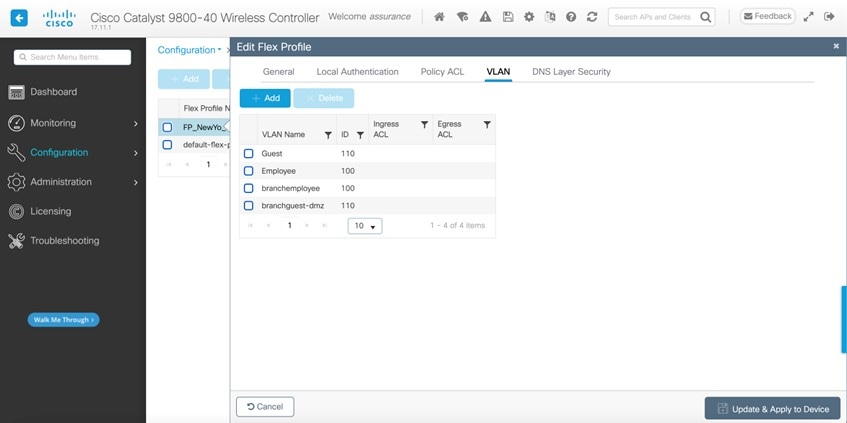
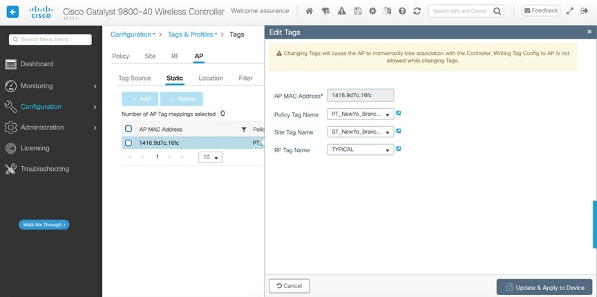
The assignment of the policy tag to the AP causes the lab3branch5 and lab3guest5 SSIDs to be broadcasted by the AP provisioned on the floor. At this point, wireless clients should be able to associate with the lab3branch5 and/or lab3guest5 SSIDs and authenticate to the network.
|
WLAN for Wireless Controller Hosted on AWS Deployment
The following steps explain how to launch a Cisco Catalyst 9800-CL Wireless Controller (C9800-CL) from the AWS Marketplace with the CloudFormation template.
Procedure
|
Step 1 |
Log in to the AWS Marketplace. 
|
||
|
Step 2 |
Search for Catalyst 9800 or C9800-CL and from the search results, click the Cisco Catalyst 9800-CL Wireless Controller for Cloud window. 
|
||
|
Step 3 |
The product overview window is displayed: 
You can read all the information about the product, support, licensing, and cost estimate for deploying the C9800-CL in the different AWS regions. If you scroll down in this window, you will be able to get information about the topology and the CloudFormation template, as shown in the following figure. 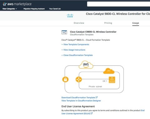
|
||
|
Step 4 |
In the top-right corner, click Continue to Subscribe. 
|
||
|
Step 5 |
Choose CloudFormation as the Fulfilment Option. 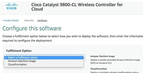
|
||
|
Step 6 |
Scroll down and choose the Region where you want to create the C9800-CL instance. 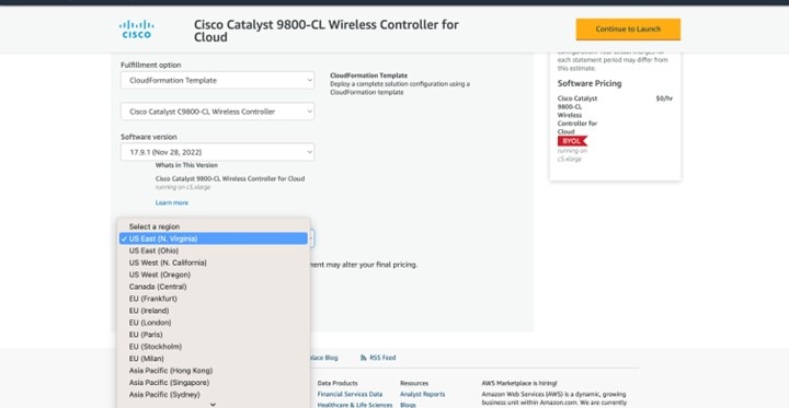
|
||
|
Step 7 |
Click Continue to Launch. |
||
|
Step 8 |
Click Launch. 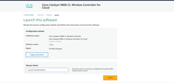
You will be automatically redirected to the CloudFormation service in the AWS console, and the following window will be displayed. 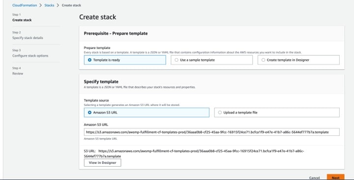
|
||
|
Step 9 |
Click Next. The template has been automatically chosen.
|
||
|
Step 10 |
Enter the Stack name and the Instance Details. |
||
|
Step 11 |
Enter the C9800 Hostname and choose the previously created key pair. 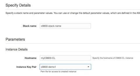
|
||
|
Step 12 |
Enter the Network Details.
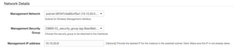
|
||
|
Step 13 |
(Optional) Enter the username and password to remotely connect to the instance. If you don’t configure the username and password, you will be able to log in through SSH using the default AWS user (ec2-user) and the instance key pair. Choose the instance type according to the scale. Cisco only supports c5.xlarge (the default value), which corresponds to the supported scale: 1000 APs and 10,000 clients. 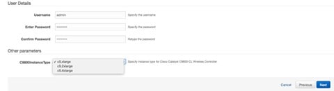
|
||
|
Step 14 |
Click Next. |
||
|
Step 15 |
For the option window, use the default settings and click Next. |
||
|
Step 16 |
Review the settings and click Submit. 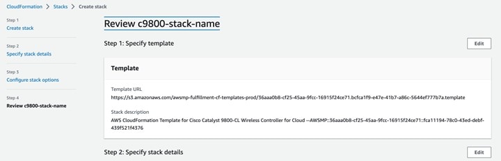
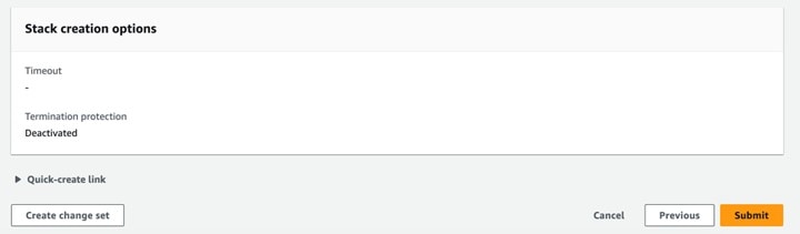
|
||
|
Step 17 |
Wait a few seconds for the status to change from CREATE_IN_PROGRESS to CREATE_COMPLETE. 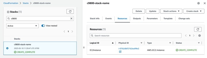
|
||
|
Step 18 |
Go to the EC2 dashboard and click Running Instances. 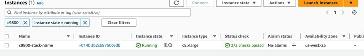
|
Configure the Cisco Catalyst 9800-CL Wireless Controller Using CLI Commands
The day zero web-based guided workflow can be skipped when configuring the CLI commands for the basic settings. After these steps, you can access the GUI for day one configuration. For the Cisco Catalyst 9800-CL Wireless Controller (C9800-CL) on AWS cloud, GigabitEthernet 1 is the only available interface and has the following characteristics:
-
Uses a Layer 3 interface (AWS only supports this type of interface).
-
Gets the IP address using DHCP.
-
Does not have a wireless CLI wizard for the Catalyst 9800-CL Wireless Controller.
Procedure
|
Step 1 |
Access the CLI commands through SSH. Use the .pem file to authenticate using the certificate, ssh -i “file name.pem” ec2-user@<c9800-CL IP> |
||
|
Step 2 |
(Optional) Set the hostname to the following: WLC(config)#hostname C9800 |
||
|
Step 3 |
Enter the config mode, and add the login credentials using the following command: C9800(config)#username <name> privilege 15 password <yourpwd> |
||
|
Step 4 |
Verify the GigabitEthernet 1 configuration and IP address. The following interface is configured for DHCP. |
||
|
Step 5 |
Disable the wireless network to configure the country code. |
||
|
Step 6 |
Configure the AP country domain. This configuration triggers the GUI to skip the day zero workflow because the Catalyst 9800 Series Wireless Controller needs a country code to be operational. Changing a country code could reset the channel and RRM grouping configuration. After implementing this command, check the customized APs for valid channel values and if the wireless controller is running in RRM One-Time mode, reassign the channels. |
||
|
Step 7 |
A certificate is needed for the AP to join the virtual Catalyst 9800 Series Wireless Controller. The certificate can be created automatically through the day zero workflow or manually using the following commands: Specify the interface to be the wireless management interface.
|
||
|
Step 8 |
To access the main dashboard, use https://<IP of the wireless management interface> and the credentials that you entered earlier. Because the box has a country code that is configured, the GUI skips the day zero window, and you can access the main dashboard for day one configuration. |
||
|
Step 9 |
For provisioning the Catalyst 9800-CL Wireless Controller from Cisco DNA Center, change the management interface from DHCP to static using the following steps:
|
||
|
Step 10 |
Click Connect. 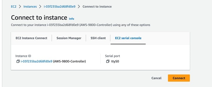
|
||
|
Step 11 |
Unconfigure |
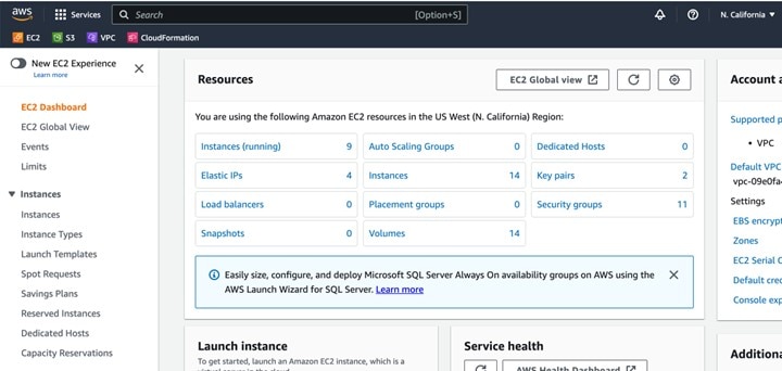
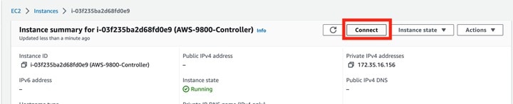
Discover and Manage the Cisco Catalyst 9800-CL Wireless Controller Deployed on AWS
The discovery process is the same for other Cisco Catalyst 9800-CL Wireless Controllers.
Provision the Cisco Catalyst 9800-CL Wireless Controller Deployed on AWS
Provision the Catalyst 9800 Series Wireless Controller so that the San Jose area is the primary managed AP location for the wireless controller.
The following steps explain how to provision the corpevent-profile wireless profile (defined in Define the wireless network) to the Catalyst 9800-CL Wireless Controller.
Procedure
|
Step 1 |
From the top-left corner, click the menu icon and choose . The Inventory window displays the devices. By default, the Focus is set to Default. |
||||||||
|
Step 2 |
Locate and check the check box for the Catalyst 9800 Series Wireless Controller. |
||||||||
|
Step 3 |
From the Actions drop-down menu, choose . |
||||||||
|
Step 4 |
Click Choose a Site. A slide-in pane is displayed, showing the site hierarchy configured for Cisco DNA Center. For this deployment guide, the Catalyst 9800 Series Wireless Controller is assigned to the building level. |
||||||||
|
Step 5 |
Expand the site hierarchy for San Jose and choose Eventcenter. |
||||||||
|
Step 6 |
Click Save to assign Catalyst 9800 Series Wireless Controller to San Jose/Eventcenter. |
||||||||
|
Step 7 |
Click Next to move to the next step in the device provisioning workflow. |
||||||||
|
Step 8 |
In the Configuration window, choose Active Main WLC for the WLC Role. |
||||||||
|
Step 9 |
Continue clicking Next until you reach the Summary window. The Summary window provides a summary of the configuration that will be provisioned to the Catalyst 9800 Series Wireless Controller. You can expand each section to see the details of the configuration. The configuration is based on the branch5 wireless profile, created in the Design the wireless network section of this deployment guide. |
||||||||
|
Step 10 |
Click Deploy to deploy the configuration to the Catalyst 9800-40 Wireless Controller. A slide-in pane is displayed. You can deploy the configuration now; you can schedule the configuration to be deployed later; or you can generate a configuration preview. If you choose to generate a preview, a preview is created, which can be deployed later on selected devices. If a site assignment is invoked during a configuration preview, the device controllability configuration will be pushed to the corresponding device(s). You can view the status in Work Items.
|
||||||||
|
Step 11 |
Click the Now radio button and click Apply to apply the configuration. You will be taken back to the Inventory window within the provisioning dashboard. The provisioning status of the device will temporarily be set to Configuring, but the status should change to Success after a few minutes. For more information about provisioning, you can click See Details directly below the provisioning status of the device. The following table shows the names of the WLAN profiles and their respective SSIDs, automatically generated by Cisco DNA Center during the provisioning of Catalyst 9800 Series Wireless Controller for this deployment guide.
An example of the WLAN configuration, as seen from the web-based GUI of Catalyst 9800 Series Wireless Controller-1, is shown in the following figure. 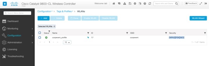
During provisioning, Cisco DNA Center creates a new policy profile in the Catalyst 9800 Series Wireless Controller. The names of the new policy profiles match the names of the created WLAN profiles. An example of the configuration, as seen from the web-based GUI of Catalyst 9800 Series Wireless Controller is shown in the following figure. 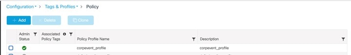
At this point in the provisioning process, the policy profiles and the WLAN profiles are not mapped to any policy tag applied to any AP. Likewise, no flex profiles have been created. |
Join New APs to the Enterprise Cisco Catalyst 9800 Series Wireless Controller
The following steps explain how to discover and join the APs to the enterprise Catalyst 9800 Series Wireless Controller.
Before you begin
For this procedure in the deployment guide, assume that new APs will use IP DHCP discovery to discover the Cisco Catalyst 9800 Series Wireless Controller. Also assume that the new APs have never been primed. A Cisco AP has been primed when it has previously joined (established a CAPWAP tunnel) a wireless controller and cached the IP address of the wireless controller in NVRAM; or when primary, secondary, or tertiary wireless controller management IP addresses have been configured within the AP. In such scenarios, the AP will give preference to the primary, secondary, or tertiary wireless controller configuration over IP DHCP discovery.
With IP DHCP discovery, DHCP servers use Option 43 to provide one or more wireless controller management IP addresses to the APs. When an AP learns the management IP address of the Catalyst 9800 Series Wireless Controller, the AP sends a CAPWAP join request message to the wireless controller. Once joined, the wireless controller manages the APs configuration, firmware, control transactions, and data transactions.
Procedure
|
Step 1 |
Configure the necessary VLANs on the Layer 2 access switches that support the Cisco APs joining the Catalyst 9800 Series Wireless Controller. This deployment guide assumes that APs are connected to Layer 2 access switches. A dedicated VLAN is on the switches for APs that are separate from end-user devices, such as PCs and IP phones. The use of a dedicated VLAN for APs and switch management is generally regarded as a design best practice, but this method does result in additional VLANs being deployed on the switches. The management VLAN (VLAN 64) is used for establishing CAPWAP tunnels to branch APs and for managing connectivity to the branch switch. The branch employee VLAN (VLAN 16) is used for locally terminating wireless traffic from the corporate event SSID on the branch switch. |
|
Step 2 |
Configure VLAN 64 and VLAN 16 on the branch switch. |
|
Step 3 |
Configure the switch port to which the AP is connected to be a trunk port, with VLANs 64 and 16 allowed and VLAN 16 as the native VLAN. Make sure the switch port is not shut down. An example is shown in the following configuration. For this deployment guide, a Microsoft Active Directory (AD) server with IP address The following example depicts the configuration of a Layer 3 switch using a VLAN switched virtual interface (SVI): |
|
Step 4 |
Connect the Cisco AP(s) to the switch port(s) on the Layer 2 access switches. The APs should get IP addresses and automatically join the Catalyst 9800 Series Wireless Controller. Once the new APs register with the wireless controller, a resync on Cisco DNA Center is automatically triggered. After the resync is complete, the new APs will show up in the inventory. Alternatively, you can manually resync the inventory for the wireless controller using the following steps:
After you have resynced the Catalyst 9800-40 wireless controller HA SSO pair (WLC-9800-2), the APs that are joined to the wireless controller should appear within the inventory. |
Provision the New APs
Once the APs have joined to the Cisco Catalyst 9800 Series Wireless Controller, they must be provisioned. Provisioning with Cisco DNA Center is necessary for the APs to receive the correct configuration to advertise the corpevent SSIDs.
Use the following steps to provision APs within Cisco DNA Center.
Procedure
|
Step 1 |
From the top-left corner, click the menu icon and choose . The main provisioning window displays the devices. By default, the Focus will be set for Inventory. |
||||||||||||||||||||||||
|
Step 2 |
Locate and check the check box for each of the APs to be provisioned. |
||||||||||||||||||||||||
|
Step 3 |
From the Actions drop-down menu, choose . You are taken through a workflow for provisioning the APs, starting with Assign Site. |
||||||||||||||||||||||||
|
Step 4 |
For each of the APs, click Choose a Site. A slide-in pane is displayed, showing the site hierarchy configured for Cisco DNA Center. Expand the site hierarchy for Milpitas and choose the building (Branch 5) and the floor (Floor 1 or Floor 2) for each AP. The following table lists the APs that are provisioned in this deployment guide, including their locations:
|
||||||||||||||||||||||||
|
Step 5 |
Click Save to save the site assignments for the APs. |
||||||||||||||||||||||||
|
Step 6 |
Click Next to advance to the next step in the provisioning workflow, Configuration. |
||||||||||||||||||||||||
|
Step 7 |
From the RF Profile drop-down list, choose the RF profile to assign to each of the APs. For this deployment guide, the TYPICAL RF profile was chosen. This RF profile was also selected as the default RF profile in Design the wireless network. |
||||||||||||||||||||||||
|
Step 8 |
Click Next to advance to the next step in the provisioning workflow, Summary. The Summary window provides a summary of the configuration that will be provisioned to each of the APs. |
||||||||||||||||||||||||
|
Step 9 |
Click Deploy to provision the APs. A slide-in pane is displayed. You can choose to deploy the configuration now, or you can schedule the configuration for later.
|
||||||||||||||||||||||||
|
Step 10 |
Click the Now radio button and click Apply to apply the configuration. A Success dialog box should be displayed, indicating that after provisioning, the APs will reboot. |
||||||||||||||||||||||||
|
Step 11 |
Click OK to confirm. The policy, site, and RF tags provisioned through Cisco DNA Center can be verified on the wireless controller GUI. At this point, wireless clients should be able to associate with the corpevent SSIDs and authenticate the network. |
Monitor and Operate the Wireless Network
This section describes daily monitoring and operations on the wireless network via Cisco DNA Center, which has already deployed the network.
Monitor Wireless Network Health
Cisco DNA Center monitors network health by calculating the score using critical Key Performance Indicators (KPIs). Device health is calculated using KPIs collected for each device. Each device type uses different KPIs to compute health. For example, APs use RF parameters such as interference, utilization, air quality, and noise, while wireless controllers use link errors, free Mbuf, packet pools, free timers, and WQE pools. Device health is presented in Cisco DNA Center at the Global site, and individual device levels under the Assurance section.
Global-Level Network Health
From the top-left corner, click the menu icon and choose . The Overall health window is displayed, showing the global-level network health defined by the ratio of healthy devices to the total number of devices.
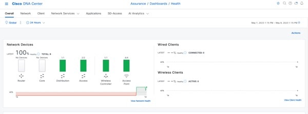
Site-Level Network Health
Click ![]() to view the site-level network health, or click
to view the site-level network health, or click ![]() to view the site-level network health summary.
to view the site-level network health summary.
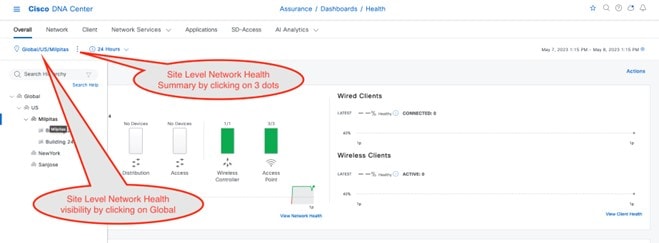
Device-Level Health
Click the Network tab. In the Network Devices dashboard, click a device name in the Device Name column.
The Device 360 window displays a 360-degree view of the network device, which shows the health change over a period of time. Hover your cursor over the timeline slider to view the health and events information about the network device over a period of time.
The health timeline is displayed at the top of the Device 360 window. The device-level details, such as model, management IP, location, current software version, and high availability status, are displayed in the Device Details area. Hover your cursor over the timeline to view more information. You can view statistics for the last 3 hours, 24 hours, or 7 days by choosing the required time from the drop-down list in the top-left corner. The health plot is available for a maximum of 30 days.
Note |
Make sure to assign the wireless controller to a site in order to view the wireless controller health. |
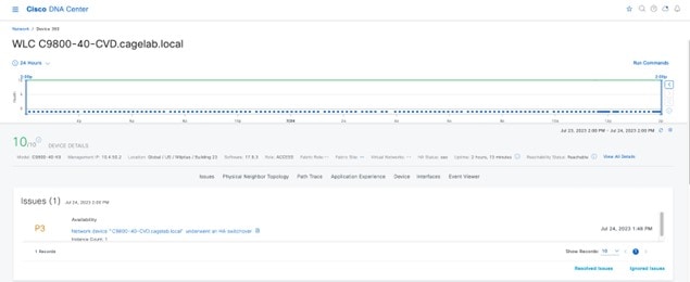
The Issues section displays major issues (if any) with a brief title of the issue. Click the corresponding issue title to view additional details about the issue. Choose , where you can enable or disable a particular category of issue and its thresholds.
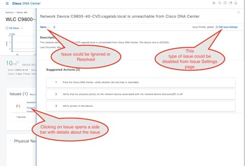
The Physical Neighbor Topology section provides a visualization of the connectivity with the next-hop devices. Hover over your cursor over a device or click a device to view additional details. The chart provides the total number of APs and clients associated with the wireless controller.
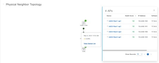
The Event viewer section consolidates the events for the wireless controller in a table format. The events associated with a syslog message can be created into an issue that is generated and shown in the Issues section. To create this custom issue, choose and click Create an Issue.
The Path Trace section helps to identify routing issues between the wireless controller and the destination device. Path trace only works if all the devices leading up to the destination device are discovered in Cisco DNA Center.
Note |
To use Live Traffic, you must enable wired endpoint data collection from . Also, all the associated devices must be provisioned from the inventory page. |
The Application Experience section shows the application traffic from wireless clients seen by the wireless controller. If the APs are in local mode, the wireless controller can be the application traffic exporter. If the APs are in flex mode, any of the switches or routers carrying the traffic must export application traffic information to Cisco DNA Center. After 17.10.1 for wireless controllers, the APs in flex mode can still send application traffic to Cisco DNA Center via wireless controllers.
The Detail Information section has Device and Interfaces subsections. The Device section has information on the wireless controller uptime, temperature, HA, and last reload reason. The charts have CPU, memory, temperature, and AP count over a period of time. The client count chart shows local, foreign, anchor, and idle information.
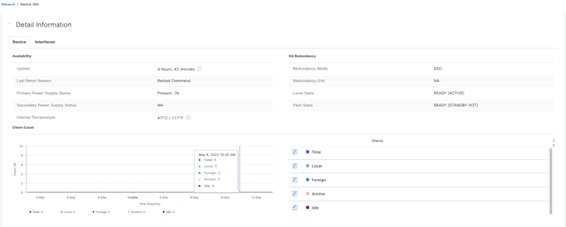
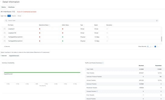
The AP 360 window has most of the charts that the wireless controller has, such as the health timeline, issues, physical neighbor topology, event viewer, and detail information sections. The AP 360 window also has AP-specific sections, such as tools to check connectivity, reload the AP, reset the radio, and control the flash LED. Under the Detail section, additional subsections exist for RF and POE that are specific to AP 360.
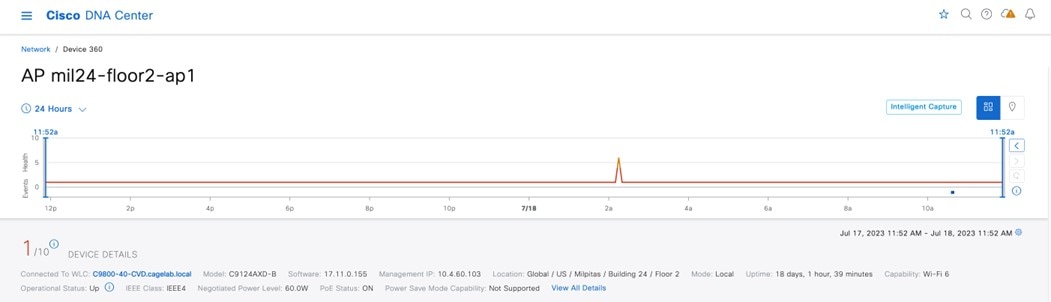
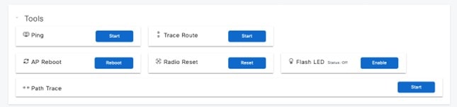
The following figure shows an example of the AP assigned to a valid policy profile, allowing the SSID starts to broadcast from the AP. After the AP starts broadcasting SSID, the memory usage interference and channel utilization increase, as shown in the following trend charts.
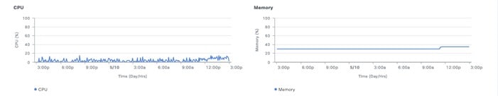
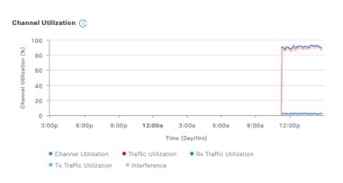
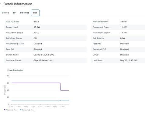
Intelligent Capture
Intelligent Capture and APs
Intelligent Capture (ICAP) allows APs to capture packets and stream statistics directly from the APs to Cisco DNA Center via a gRPC tunnel. This feature requires the AP to be able to reach Cisco DNA Center directly via port 32626. If there is a firewall between the AP and Cisco DNA Center, this traffic needs to be allowed via the 32626 port. Up to the latest release Cisco DNA Center of 2.3.5.0, there is a scale limit of 1000 APs that can be enabled for statistics. By default, the ICAP application is not installed when shipped from the factory, so you must install the package from the Software Management window. The following figure shows that the Intelligent Packet Capture package is not yet installed as shipped from the factory.
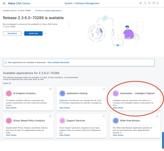
Choose the Automation – Intelligent Capture package and click Install to install the application. Once it is installed, the AP 360 page displays the Intelligent Capture button at the top right of the 360 page. Click the Intelligent Capture button to open a side bar. Click Enable RF Statistics at the top-right corner of the page to enable RF statistics. Alternatively, you can enable the RF statistics from the Intelligent Capture Settings page by navigating to . Enabling the RF statistics takes a few minutes, based on the scale on the Cisco DNA Center. Once enabled, the charts in the Intelligent Capture window display statistics for clients, channel utilization, Tx/RX frame count, frame errors, Tx power, and multicast or broadcast counts as shown in the following figure. The statistics are updated every 30 seconds. Click either Enable RF Statistics or Disable RF Statistics to change the band of the AP.
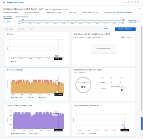
Click the Spectrum Analysis tab to enable an AP. Click Start Spectrum Analysis to configure an AP to start capturing spectrum analysis data and stream it to the Cisco DNA Center, as shown in following figure. The spectrum analysis can only run for 10 minutes at a time.
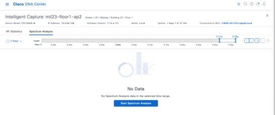
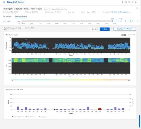
Once Spectrum Analysis is enabled and shown in Cisco DNA Center, it stays for 30 days and can be revisited by choosing that time frame and a duration (1, 3, or 5 hours), using the left or right arrow buttons. This feature is designed to be used live during a short period to capture RF conditions when an interference event is happening.
Intelligent Capture and Wireless Clients
ICAP enables live or scheduled packet capture for any wireless client that associates with an AP that is discovered by Cisco DNA Center. An ICAP page in the Client 360 window also provides additional live statistics about the client, such as RF statistics, average data rate, and packet count over a period of time. The window also provides the events associated with client onboarding and a maps section showing the location of the client on the floor map if CMX/Cisco Spaces is integrated into Cisco DNA Center. The following figure shows the ICAP page for a wireless client before the onboarding packet capture is enabled.
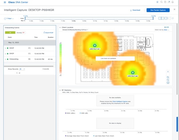
Click Run Packet Capture in the top-right corner of the window to enable the onboarding packet capture. You can schedule this capture by clicking Client Intelligent Capture, which will bring you to the ICAP settings page. While enabling the onboarding packet capture, you can choose the desired wireless controller. A selected wireless controller will show a green check mark to the left of the wireless controller name. By default, the wireless controller where the client is currently associated will be selected, as shown in the following figure.
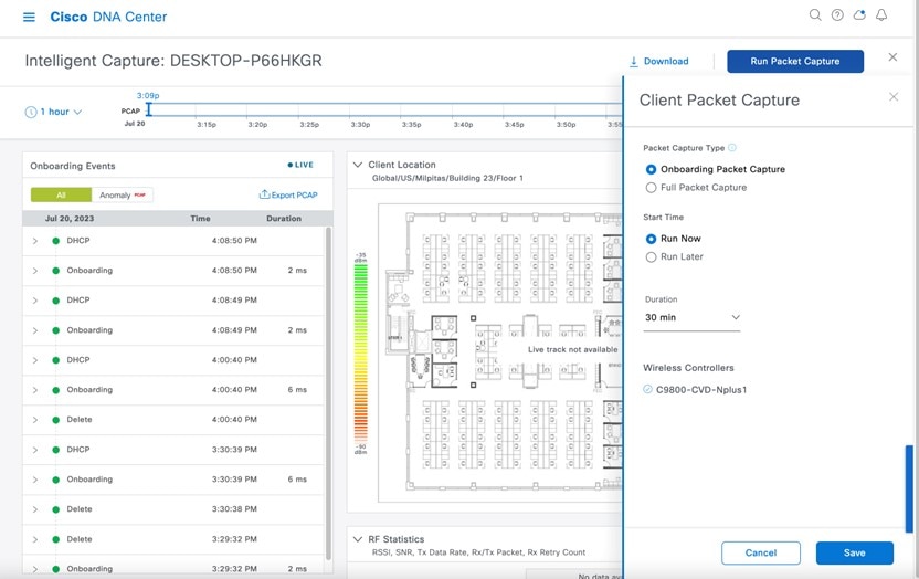
Once you click Save, it will take several minutes to configure the wireless controller and AP to send the live packet capture for the wireless client, as shown in the following figure.
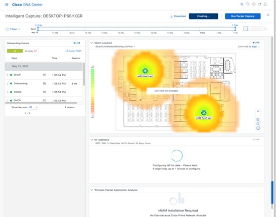
After the wireless controller and APs are configured, live statistics about the client are displayed in the charts, as shown in following figure.
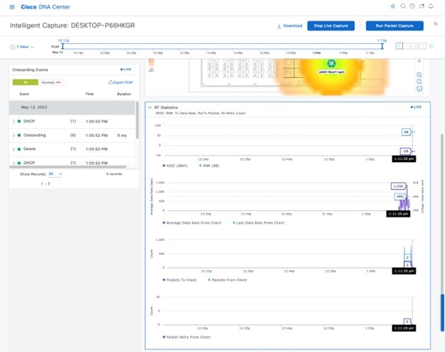
On the wireless controller and the AP, the configured settings can be verified using the following CLI:
-
C9800-40-CVD#show ap icap serviceability detail
AP name : mil23-floor1-ap1AP serviceability gRPC server status WLC timestamp : 05/12/2023 13:29:55 AP timestamp : 05/12/2023 13:29:54 Status : ready Last success timestamp : 05/12/2023 13:29:54 Last failure timestamp : 12/31/1969 16:00:00 Last failure status : idle Last JWT success timestamp : 05/12/2023 13:27:35 Last JWT failure timestamp : 12/31/1969 16:00:00 Last JWT failure reason : Unknown Packet transmit attempts : 53 Packet transmit failures : 0 Packet receive count : 1061 Packet receive failures : 0 Full packet-trace stats AP timestamp : 05/12/2023 13:29:54 Packets received : 0 Packets sent : 0 Packets filtered : 0 Packets dropped : 0 Packets dropped while disabled : 0 Packets dropped without JWT : 0 Partial packet-trace stats AP timestamp : 05/12/2023 13:29:54 Packets received : 1061 Packets sent : 262 Packets filtered : 799 Packets dropped : 0 Packets dropped while disabled : 0 Packets dropped without JWT : 0 Anomaly detection event stats AP timestamp : 05/12/2023 13:29:54 Packets received : 0 Packets sent : 0 Packets filtered : 0 Packets dropped : 0 Packets dropped while disabled : 0 Packets dropped without JWT : 0 Anomaly detection packet stats AP timestamp : 05/12/2023 13:29:54 Packets received : 0 Packets sent : 0 Packets filtered : 0 Packets dropped : 0 Packets dropped while disabled : 0 Packets dropped without JWT : 0 Statistics stats AP timestamp : 05/12/2023 13:29:54 Packets received : 0 Packets sent : 15165 Packets filtered : 0 Packets dropped : 2 Packets dropped while disabled : 0 Packets dropped without JWT : 2 -
mil23-floor1-ap1#show ap icap subscription
Subscription list
-----------------
	Full Pkt Capture      : Disabled
	Partial Pkt Capture   : Enabled
	Anomaly Event         : Disabled
	Debug                 : Disabled
	Stats                 : Enabled
	Ap Operational Data   : Disabled
       Sensor Message        : Disabled
	RRM Operational Data  : Disabled
	Client Events         : Disabled
	MMAP Packets          : Disabled
	aWIPS Forensic Pkts   : Disabled
MAC and Filters subscription list
---------------------------------
Full-packet-trace: None
Partial-packet-trace: 1C:1B:B5:1F:C0:F7
	Filters: assoc auth probe arp dhcp eap icmp dhcpv6 icmpv6 dns ndp
Anomaly Detection: None

Client Stats
------------
MAC Address Table:
	 1C:1B:B5:1F:C0:F7

RF Spectrum
-----------
Radio Slot(s): NONE
mil23-floor1-ap1#
Once ICAP for onboarding events is enabled and the client is deauthenticated and reauthenticated, the packets are captured during those events and sent to Cisco DNA Center. The events with captured packets will have a PCAP icon to the right side of the event name in the onboarding events section. Once you select an event, it will show the analysis of the captured packets in a visual format. The captured packets can be downloaded as a PCAP file by clicking Download Packets in the top-right corner of the Auto Packet Analyzer section. The captured packets of a group of events can be downloaded by clicking Export PCAP in the Onboarding Events section. Export PCAP is intended for the full set of events, and Download Packets should be used for subevents.
In order to capture the data packets from clients, the full packet capture needs to be enabled as shown in the following figure.
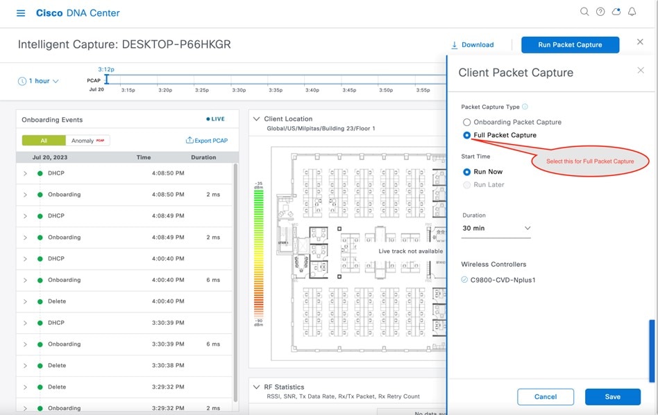
Click Save to enable the full packet capture. Click the download icon to download the packets as a PCAP file, as shown in the following figure.
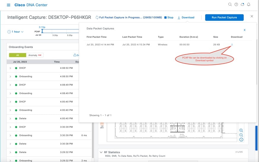
Rogue and Adaptive Wireless Intrusion Prevention
Rogue Management
The Rogue Management application in Cisco DNA Center detects and classifies threats and enables network administrators, network operators, and security operators to monitor network threats. Cisco DNA Center helps to quickly identify the highest-priority threats and allows you to monitor these threats in the Rogue and aWIPS dashboard within Cisco DNA Assurance.
A rogue device is an unknown AP or client that is detected by the managed APs in your network. A rogue AP can disrupt wireless LAN operations by hijacking legitimate clients. A hacker can use a rogue AP to capture sensitive information, such as usernames and passwords. The hacker can then transmit a series of clear-to-send (CTS) frames. This action mimics an AP informing a particular client to transmit, while instructing all the others to wait, which results in legitimate clients not being able to access network resources. As a result, wireless LAN service providers have a strong interest in banning rogue APs from the air space.
Cisco DNA Center constantly monitors all the nearby APs and automatically discovers and collects information about rogue APs.
When Cisco DNA Center receives a rogue event from a managed AP, it responds in the following ways:
-
If the unknown AP is not managed by Cisco DNA Center, Cisco DNA Center applies the rogue classification rules.
-
If the unknown AP is not using the same SSID as your network, Cisco DNA Center verifies whether the AP is connected to the corporate wired network and extends to the wired network. If the rogue AP is physically connected to the switch port of the corporate network, Cisco DNA Center classifies the AP as Rogue on wire.
Cisco switches managed by Cisco DNA Center are required for rogue on wire to work.
-
If the AP is unknown to Cisco DNA Center, and is using the same SSID as your network, Cisco DNA Center classifies the AP as a Honeypot.
-
If the unknown AP is not using the same SSID as your network and is not connected to the corporate network, Cisco DNA Center verifies whether it is causing any interference. If it is, Cisco DNA Center classifies the AP as Interferer and marks the rogue state as Potential Threat. The threshold level for classifying the interferers on the network is greater than -75 dBm.
-
If the unknown AP is not using the same SSID as your network, and is not connected to the corporate network, Cisco DNA Center verifies whether it is a neighbor. If it is a neighbor, Cisco DNA Center classifies the AP as Neighbor and marks the rogue state as Informational. The threshold level for classifying the rogue AP as a neighbor AP is less than or equal to -75 dBm.
Adaptive Wireless Intrusion Prevention
The Cisco Advanced Wireless Intrusion Prevention System (aWIPS) is a wireless intrusion threat detection and mitigation mechanism. aWIPS uses an advanced approach to wireless threat detection and performance management. An AP detects threats and generates alarms. It combines network traffic analysis, network device and topology information, signature-based techniques, and anomaly detection to deliver complete and highly accurate wireless threat prevention.
With a fully infrastructure-integrated solution, you can continually monitor wireless traffic on both wired and wireless networks and use that network intelligence to analyze attacks from many sources. You are able to accurately pinpoint attacks and proactively prevent attacks, rather than wait until damage or exposure has occurred.
Because the aWIPS functionality is integrated into Cisco DNA Center, aWIPS can configure and monitor aWIPS policies and alarms and report threats.
aWIPS supports the following capabilities:
-
Static signatures
-
Standalone signature detection
-
Alarms
-
Static signature file packaged with controller and AP image
Cisco DNA Center supports the following signatures that detect various denial of service (DoS) attacks:
-
Authentication flood: A form of DoS attack that floods an AP's client-state table (association table) by imitating many client stations (MAC address spoofing) and sending authentication requests to the AP. Upon reception of each individual authentication request, the target AP creates a client entry in State 1 of the association table. If open system authentication is used for the AP, the AP returns an authentication success frame and moves the client to State 2. If Shared Key Authentication (SHA) is used for the AP, the AP sends an authentication challenge to the attacker's imitated client, which does not respond, and the AP keeps the client in State 1. In either of these scenarios, the AP contains multiple clients hanging in either State 1 or State 2, which fills up the AP association table. When the table reaches its limit, legitimate clients are not able to authenticate and associate with this AP.
-
Association flood: A form of DoS attack that aims to exhaust an AP's resources, particularly the client association table, by flooding the AP with many spoofed client associations. An attacker using such a vulnerability can emulate many clients to flood a target AP's client association table by creating many clients. When the client association table overflows, legitimate clients cannot get associated.
-
CTS Flood: A form of DoS attack when a specific device sends a bulk Clear To Send (CTS) control packet to wireless devices sharing the same radio frequency (RF) medium. This kind of attack blocks wireless devices from using the RF medium until the CTS flood stops.
-
RTS Flood: A form of DoS attack when a specific device sends a bulk RTS control packet to an AP for blocking wireless bandwidth, which leads to performance disturbance for the clients on that AP.
-
Broadcast Probe: A form of DoS attack when a specific device tries to flood a managed AP with broadcast probe requests.
-
Disassociation Flood: A form of DoS attack that aims to send an AP to the unassociated or unauthenticated State 2 by spoofing disassociation frames from the AP to a client. With client adapter implementations, this form of attack is effective in immediately disrupting wireless services against this client. Typically, client stations reassociate to regain service until the attacker sends another disassociation frame. An attacker repeatedly spoofs the disassociation frames to keep the client out of service.
-
Disassociation Broadcast: A form of DoS attack when a specific device triggers a disassociation broadcast to disconnect all the clients.
This attack aims to send an AP's client to the unassociated or unauthenticated State 2 by spoofing disassociation frames from the AP to the broadcast address of all the clients. With current client adapter implementations, this form of attack immediately disrupts wireless services against multiple clients. Typically, client stations reassociate to regain service until the attacker sends another disassociation frame. An attacker repeatedly spoofs the disassociation frames to keep all the clients out of service.
-
Deauthentication flood: A form of DoS attack that aims to send an AP's client to the unassociated or unauthenticated State 1 by spoofing deauthentication frames from the AP to the client unicast address. With the current client-adapter implementations, this form of attack immediately disrupts wireless services against the client. Typically, client stations reassociate and reauthenticate to regain service until the attacker sends another deauthentication frame. An attacker repeatedly spoofs the deauthentication frames to keep all the clients out of service.
-
Deauthentication broadcast: A form of DoS attack that sends all the clients of an AP to the unassociated or unauthenticated State 1 by spoofing deauthentication frames from the AP to the broadcast address. With client adapter implementation, this form of attack immediately disrupts wireless services against multiple clients. Typically, client stations reassociate and reauthenticate to regain service until the attacker sends another deauthentication frame.
-
EAPOL logoff flood: A form of DoS attack when a specific device tries to send Extensible Authentication Protocol over LAN (EAPOL) logoff packets, which are used in the WPA and WPA2 authentication for (DoS).
Because the EAPOL logoff frame is not authenticated, an attacker can potentially spoof this frame and log out a user from an AP, thus committing a DoS attack. The fact that the client is logged out from the AP is not obvious until the client attempts communication through the WLAN. Typically, the disruption is discovered and the client reassociates and authenticates automatically to regain the wireless connection. The attacker can continuously transmit the spoofed EAPOL-logoff frames.
Basic Setup Workflow
To install the Rogue and aWIPS application in Cisco DNA Center, click the menu icon and choose . Choose the Rogue and aWIPS package, and click Install in the bottom-right corner, as shown in the figure below.
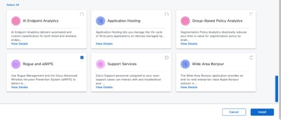
After installing the package, navigate to .
For more information on how to configure Rogue and aWIPS in Cisco DNA Center, see the Cisco DNA Center Rogue Management and aWIPS Application Quick Start Guide.
POE Charts
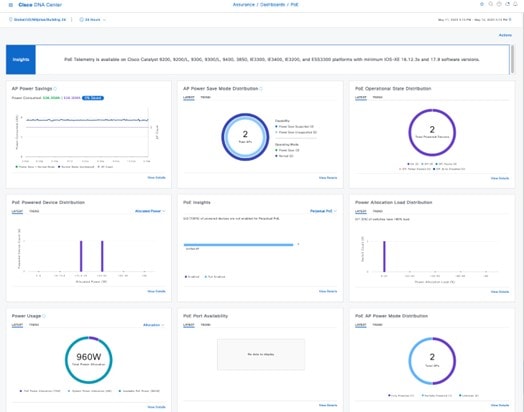
POE charts are available in the AP 360 window, which provides a timeline view of the power consumed by the AP over the selected period of time.
Cisco Aironet 1800S Network Sensors
As wireless networks grow, it is imperative that wireless issues are identified proactively and resolved. Network sensors are small form factor devices that can be deployed in office spaces, such as conference rooms, work areas, where wireless coverage is critical and does not require an on-site IT technician. These sensors act as wireless clients, which can run on-demand or scheduled synthetic tests. For more information, see the Cisco Aironet Active Sensor Deployment Guide.
Cisco Spaces and CMX Integration
CMX On-premise Integration
To integrate the on-premise CMX, click the menu icon and choose . Click Add under CMX Servers, and in the Add CMX Server slide-in pane, enter the requested values, as shown in figure below. After entering the values, click Add.
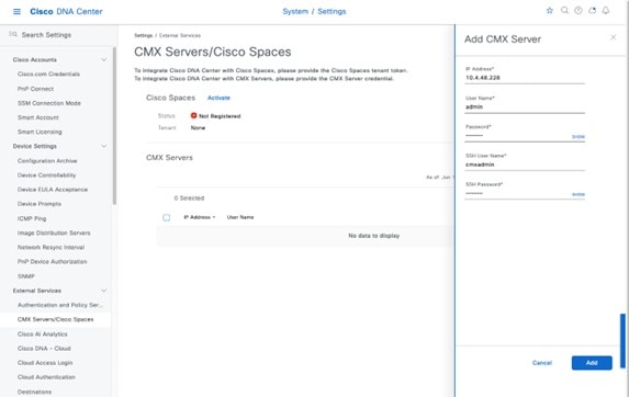
To assign CMX to a site, navigate to , and click the Wireless tab. Click the Cisco Spaces/CMX Servers tab, as shown in the following figure.
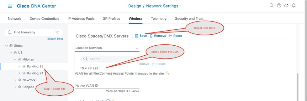
From the left hierarchy tree, select the desired site. From the Location Services drop-down list, choose the CMX server. The following figure shows an example CMX server for the selected Milpitas site.
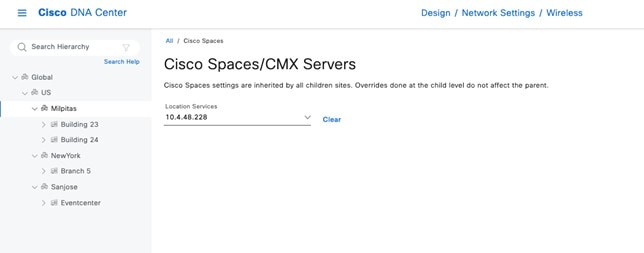
Once the location is assigned for the CMX, the site hierarchy related to that site, the APs in that site, and the AP position information will be synced with CMX.
Note |
Integrating CMX with Cisco DNA Center will not automatically add the wireless controller to the CMX. You must add the wireless controller manually on the CMX using the CMX GUI interface. |
Use the following steps to add the wireless controller to the CMX.
-
Login to CMX GUI interface and navigate to SYSTEM, as shown in the following figure.
Figure 200. CMX GUI to Add Wireless Controller 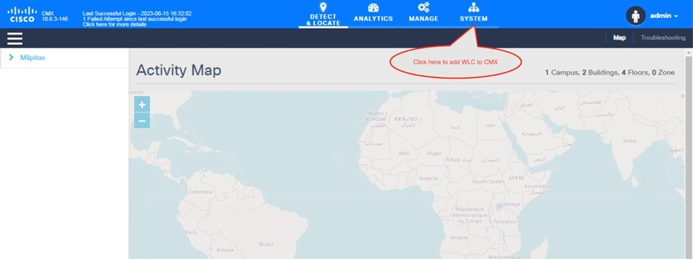
-
Click + to add the wireless controller to the CMX.
Figure 201. Adding Wireless Controller within the SYSTEM in CMX 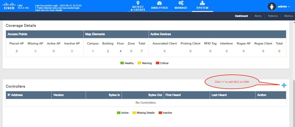
-
From , click Advanced to add an individual wireless controller.
The Import from Cisco Prime dialog box is displayed.
Figure 202. Add an Individual Wireless Controller to the CMX 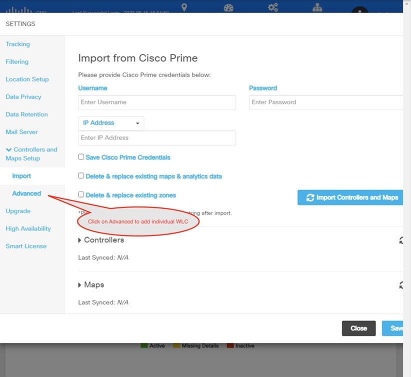
-
Scroll down and click Add Controller to add the wireless controller to the CMX, as shown in the following figure.
Figure 203. Add Individual Wireless Controller Information 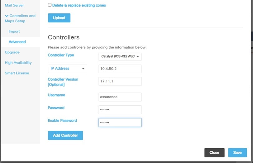
-
Click Save.
The list of wireless controllers is displayed.
Figure 204. List of Wireless Controllers 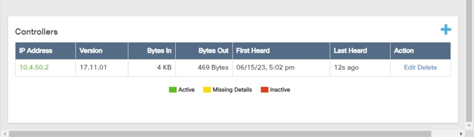
Integrate Cisco Spaces with Cisco DNA Center
Use this procedure to activate your Cisco Spaces account and integrate it with Cisco DNA Center. For more information, see the Cisco Spaces Configuration Guide.
Before you begin
To integrate Cisco Spaces with Cisco DNA Center, you must have a Cisco Spaces account.
Procedure
|
Step 1 |
To activate your account in dnaspace.io, send an email to cisco-dnaspace-support@external.cisco.com. An activation link will be sent to the email address that you used to request the activation. |
||
|
Step 2 |
Generate a token from dnaspaces.io for Cisco DNA Center integration and copy the token. 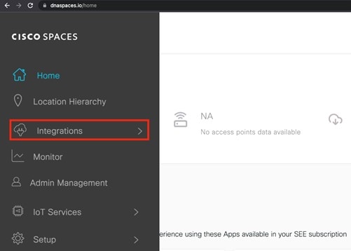
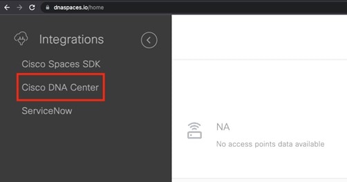
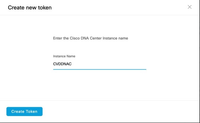
|
||
|
Step 3 |
Log in to the Cisco DNA Center UI. |
||
|
Step 4 |
From the top-left corner, click the menu icon and choose . |
||
|
Step 5 |
Click Activate next to Cisco Spaces. |
||
|
Step 6 |
In the dialog box, paste the token that was copied from dnaspaces.io. 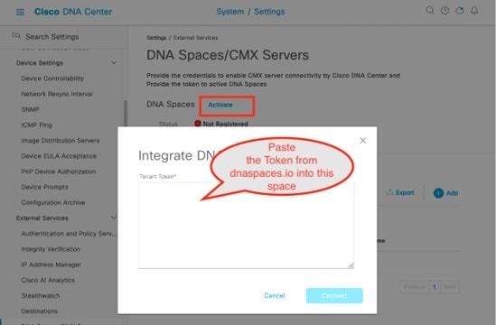
|
||
|
Step 7 |
If the wireless controller cannot reach dnaspaces.io, download a Cisco Spaces connector and deploy it on premises where it can reach both the wireless controller and dnaspaces.io. This process requires the dual interface version of the Cisco Spaces connector. For more information, see the "Retrieving a Token for a Connector from Cisco Spaces (Wireless)" topic in the Cisco Spaces: Connector Configuration Guide. Primary interface information will be requested the first time the connector is powered on. The secondary interface values have to be entered via the CLI, as provided in the document. If the connector requires a proxy to reach dnaspaces.io, it has to be added via the connector UI interface. |
||
|
Step 8 |
Log in to dnaspaces.io and click the menu icon and choose . |
||
|
Step 9 |
Click Create Connector and enter a name for the connector. 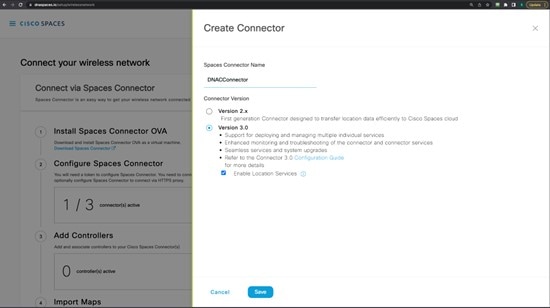
|
||
|
Step 10 |
Choose the connector that was recently created and click Generate Token. 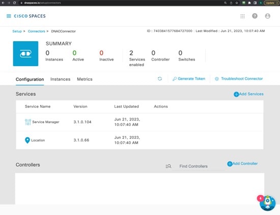
|
||
|
Step 11 |
Log in to the Cisco Spaces connector GUI and enter the token to register this deployed connector with dnaspaces.io. 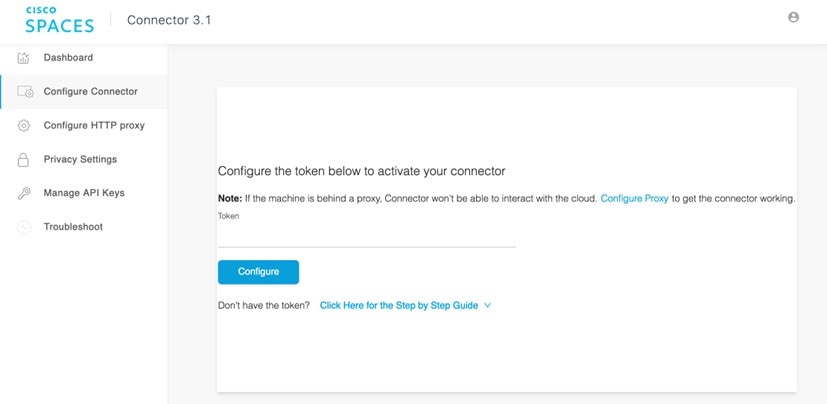
|
||
|
Step 12 |
After the connector is registered with dnaspaces.io successfully, the wireless controller can be added from the connector instance in dnaspace.io. |
||
|
Step 13 |
Log in to dnaspaces.io and click the menu icon and choose . |
||
|
Step 14 |
Click Add Controller. |
||
|
Step 15 |
Choose Catalyst 9800 Wireless Controller for the Controller Type. |
||
|
Step 16 |
Enter the username and password and click Save. 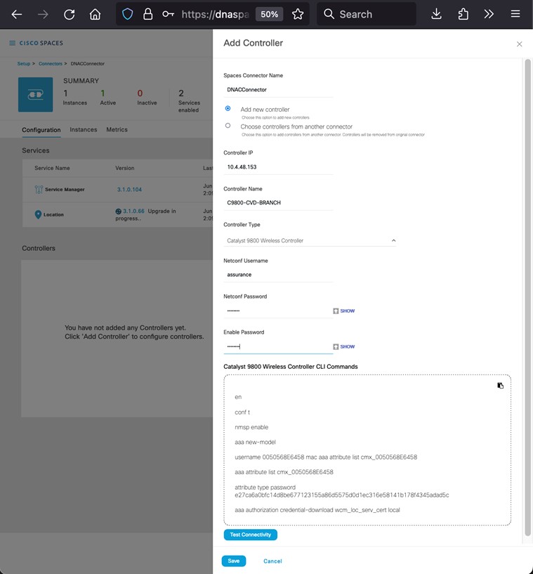
|
||
|
Step 17 |
Wait several minutes for the wireless controller to show as Active in dnaspace.io. |
||
|
Step 18 |
Navigate to the Cisco DNA Center UI. |
||
|
Step 19 |
From the top-left corner, click the menu icon and choose . |
||
|
Step 20 |
Click Cisco Spaces/CMX Servers. |
||
|
Step 21 |
Choose your account from the Location Services drop-down list. |
||
|
Step 22 |
From the left hierarchy tree, expand Global and choose the site that will use Cisco Spaces to track the client location. |
||
|
Step 23 |
Click Save.
|
Integrate On-Premise Cisco CMX with Cisco DNA Center
Use this procedure to integrate the on-premise Cisco Connected Mobile Experiences (CMX) with Cisco DNA Center.
Procedure
|
Step 1 |
From the top-left corner, click the menu icon and choose . |
||
|
Step 2 |
From CMX Servers, click Add. The Add CMX Server slide-in pane is displayed. |
||
|
Step 3 |
Enter the requested information into the relevant fields.
|
||
|
Step 4 |
Click Add. |
||
|
Step 5 |
To assign CMX to a site(s), click the menu icon and choose . |
||
|
Step 6 |
Click Cisco Spaces/CMX Servers.
|
||
|
Step 7 |
From the Location Services drop-down list, select the CMX server. The following figure shows an example CMX server 10.4.48.228 for the Milpitas site.
Once the location is assigned for the CMX server, the site hierarchy related to that site, the APs in that site, and the AP position information will be synced with the CMX server.
|
Hardware Upgrade, Refresh, and Replacement
Replace Cisco Wireless Controller
Cisco DNA Center does not support a workflow to replace the wireless controller, but the replacement needs to be directly performed on the wireless controller. If one of the boxes in a SSO pair fails and must be replaced, Cisco recommends that you follow this procedure to put the device back in the cluster while avoiding any disruptions to the wireless network.
Procedure
|
Step 1 |
Physically disconnect the failed box and send the box in for Return Material Authorization (RMA). |
|
Step 2 |
Make sure that the active wireless controller is configured with a higher chassis priority (= 2). |
|
Step 3 |
When you receive the new box, before you connect it to the network and to the existing Cisco Catalyst 9800 Series Wireless Controller, configure the basic parameters offline: login credentials, IP connectivity, and redundancy configuration, including RMI (if applicable). Remember to set the chassis priority to 1, so when SSO pair is formed, this box will become the standby and will not disrupt the existing active wireless controller. |
|
Step 4 |
Save the configuration on the new box and power it off. |
|
Step 5 |
Physically connect the new Cisco Catalyst 9800 Series Wireless Controller to the network (uplink and RP ports). |
|
Step 6 |
Power on the new box. |
|
Step 7 |
The box will boot up, and the SSO pair will be formed again, with the new box going to standby hot state. |
Replace an AP
Use the following procedure to replace the AP hardware. Cisco DNA Center provides an AP hardware replacement guided workflow for reasons such as hardware failure.
Before you begin
-
Cisco DNA Center should have provisioned the AP to be replaced.
-
The AP to be replaced should be in unreachable state.
-
The new AP is registered with the wireless controller where the older AP was registered.
-
The new AP is visible in Cisco DNA Center inventory window.
When replacing the AP, the old AP and the new AP have to be the same model. If you are replacing the old AP with a different model, use the Access Point Refresh workflow that is explained in the following subsection.
Procedure
|
Step 1 |
From the top-left corner, click the menu icon and choose . 
|
|
Step 2 |
In the Get started window, enter a unique Task Name for your workflow. 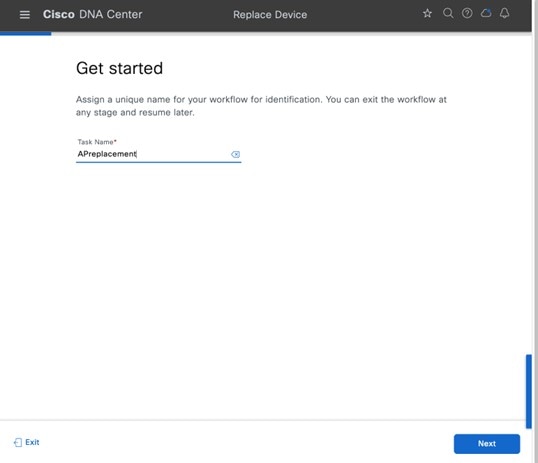
|
|
Step 3 |
In the Choose Device Type window, choose AP. 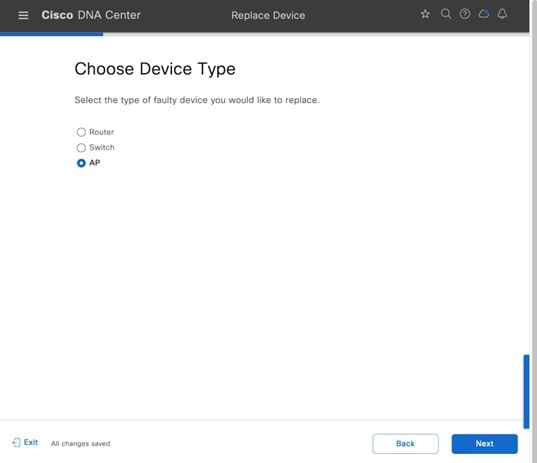
|
|
Step 4 |
In the Choose Site window, choose the site in which AP needs to be replaced. 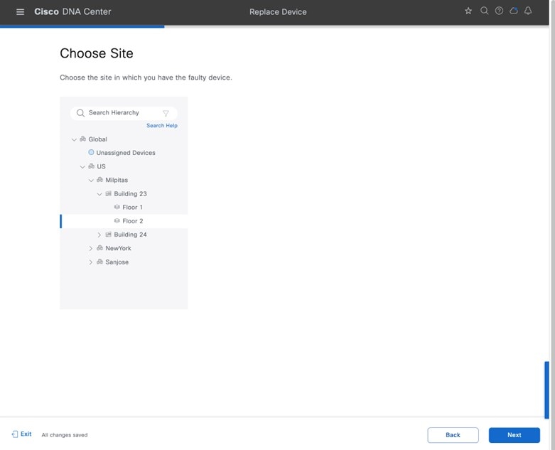
|
|
Step 5 |
In the Choose Faulty Device window, if you don't find an AP, do the following:
|
|
Step 6 |
In the Choose Replacement Device window, choose a replacement device from the Unclaimed tab or Managed tab. The Unclaimed tab shows the devices that are onboarded through PnP. The Managed tab shows the devices that are onboarded either through inventory or the discovery process. 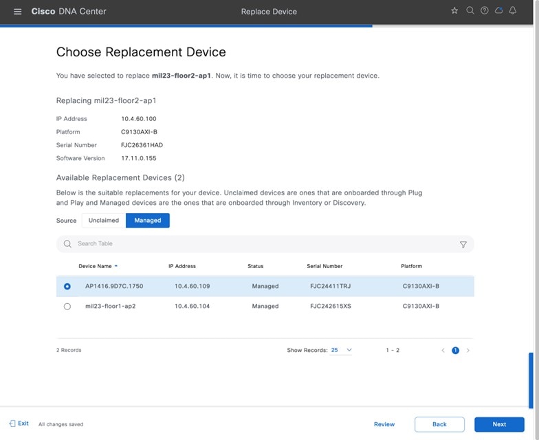
|
|
Step 7 |
In the Schedule Replacement window, click Now to start device replacement immediately, or click Later to schedule device replacement at a specific time. 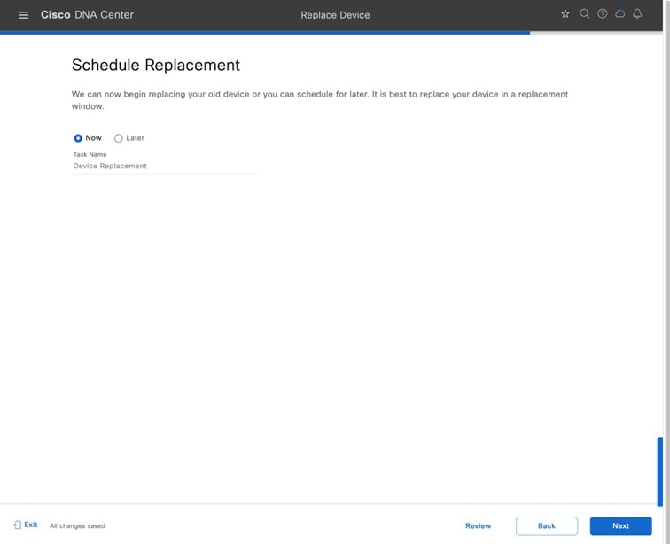
|
|
Step 8 |
In the Summary window, review the configuration settings. 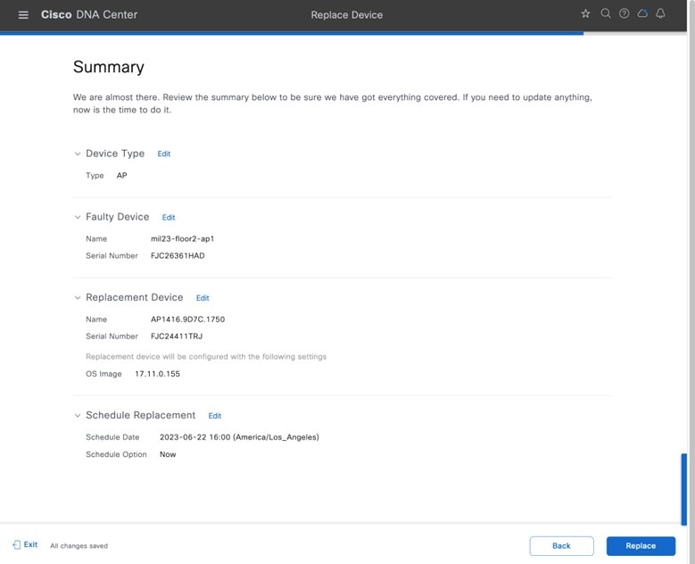
|
|
Step 9 |
Click Monitor Replacement Status to go to the Mark for Replacement view in the Provision window. |
|
Step 10 |
Device 360 window displays the RMA in the timeline and the Event table. 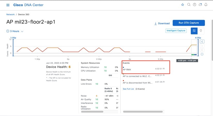
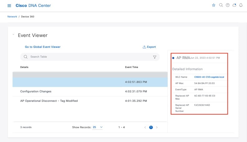
|
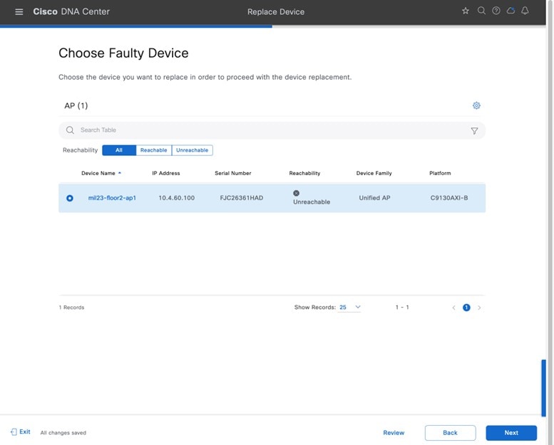
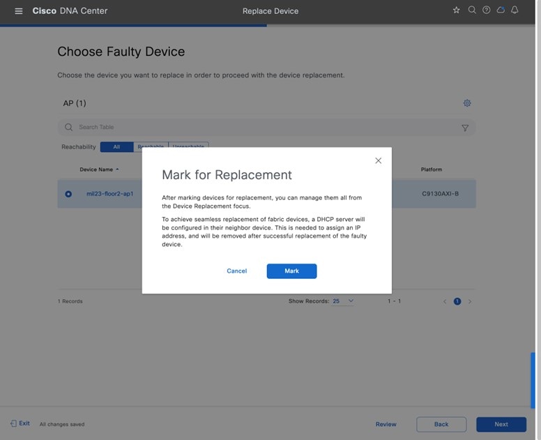
AP Refresh
Cisco DNA Center provides the AP hardware refresh guided workflow. You can use the following procedure to replace old APs with new ones in Cisco DNA Center.
Before you begin
-
The old AP site must be provisioned.
-
Ensure that the old AP is in the unreachable state.
-
The new AP must be registered with the wireless controller where the old AP is registered.
-
The new AP must be available in the Cisco DNA Center inventory.
When replacing an AP with an internal antenna with an AP with an external antenna, the angles of the external antenna are to be manually set and vice versa.
Procedure
|
Step 1 |
From the top-left corner, click the menu icon and choose . 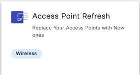
|
|
Step 2 |
In the Get Started window, enter a unique name for the task, and click Next. 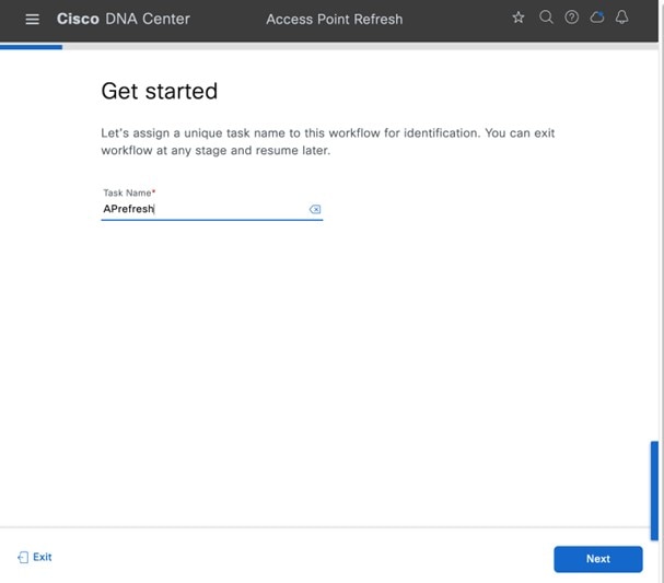
|
|
Step 3 |
In the Select Access Points window, do the following:
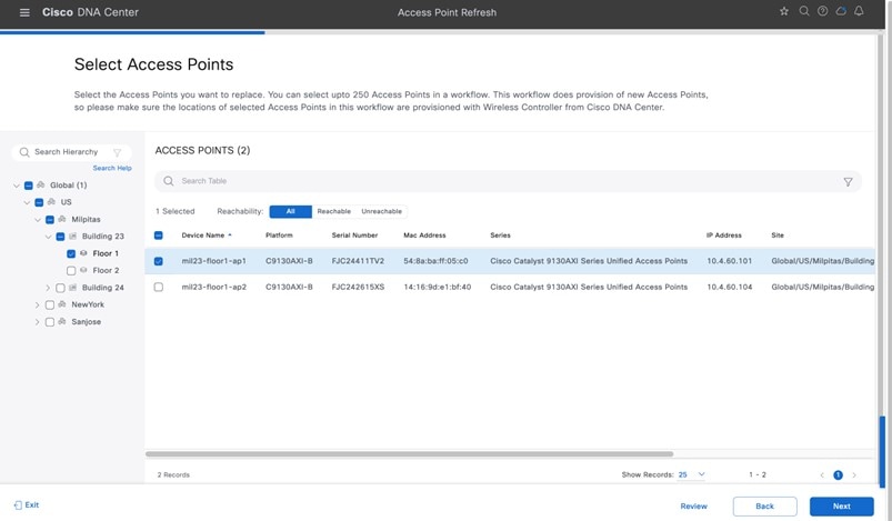
|
|
Step 4 |
In the Assign New APs to Old APs window, to add the new AP details using comma-separated value (CSV) file, do the following:
|
|
Step 5 |
To add the new AP details using the GUI, click the edit icon ( 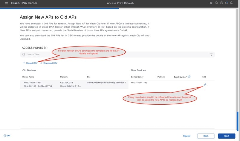
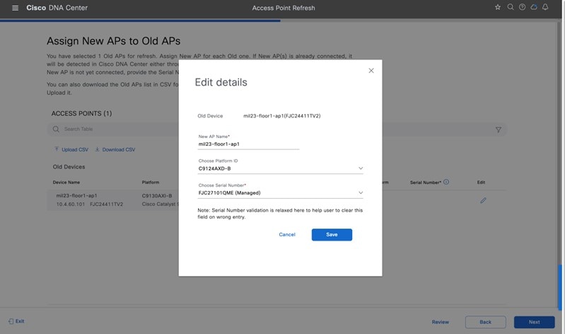
|
|
Step 6 |
Click Save, and click Next to view the refresh summary. 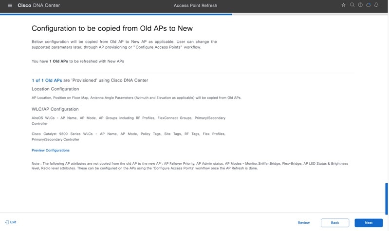
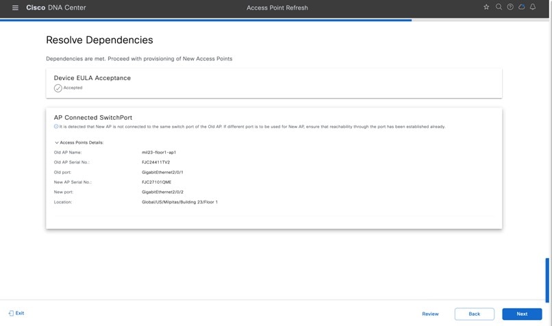
|
|
Step 7 |
In the Schedule Access Point Refresh Task window, click Now to start AP refresh immediately, or click Later to schedule AP refresh at a specific time. 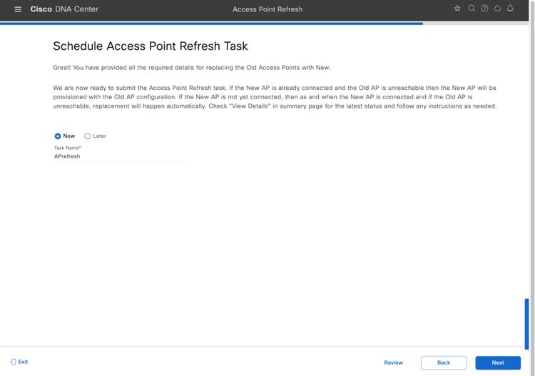
|
|
Step 8 |
In the Summary window, review the configuration settings. 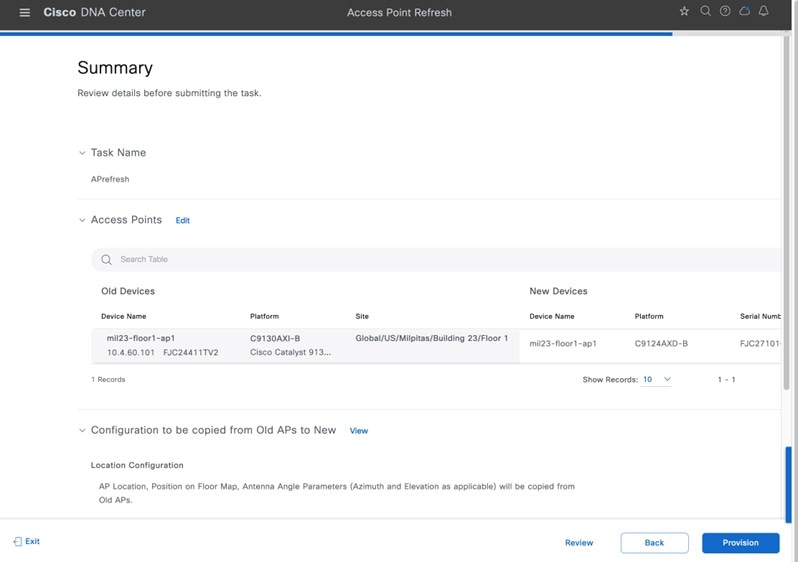
|
|
Step 9 |
Click Provision to start the provisioning. |
|
Step 10 |
In the Track Replacement Status window, click Download Report to download the provisioning status report. 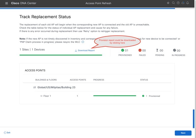
|
|
Step 11 |
An Assurance AP 360 page displays the AP refresh timeline in the time travel and Events table as shown in the following figures. 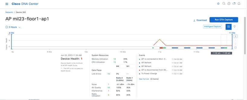
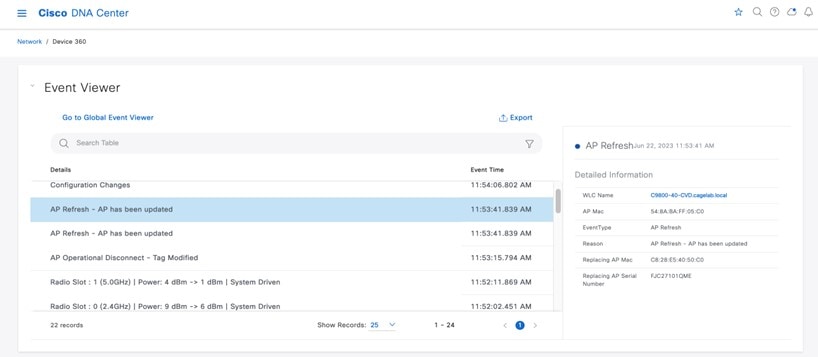
|
 ) for the AP, and in the
 Cloud-Based AI Enhancements
Cisco DNA Center has AI-based enhancements that leverage the power of machine learning (ML) and machine reasoning (MR) to provide accurate insights that are specific to your network deployment. The AI-based features include Radio Resource Management (RRM) and broadly AI-based Analytics, which provides network insights and deviations from the baseline.
Cisco AI RRM
AI-enhanced RRM integrates the power of artificial intelligence (AI) and ML into the reliable and trusted Cisco RRM product family algorithms in the cloud. AI-enhanced RRM is coordinated through Cisco DNA Center (an on-premises appliance) as a service. Existing Cisco Catalyst 9800 RRM sites can transition seamlessly to an intelligent, centralized service. As with other Cisco DNA Center services, AI-enhanced RRM brings a host of new features with it. Learn more here.
Cisco AI Analytics
Cisco AI Analytics provides insights and charts that help network administrators troubleshoot network issues and conduct long-term capacity planning. Learn more here.
Mesh Networks
Cisco outdoor APs can be operated with a wired network for backhaul, or with a mesh network using a 5-GHz or 2.4-GHz radio as the backhaul. In a Cisco wireless mesh network, multiple mesh APs form a network that provides secure, scalable wireless LAN. APs in a mesh network operate through root access point (RAP) or mesh access point (MAP). RAPs are connected to the wired network at each location. All downstream APs operate as MAPs and communicate using wireless links. All APs are configured and shipped as mesh APs. To use an AP as a RAP, any MAP must be reconfigured as RAP. All mesh networks must contain at least one RAP.
Details on how to use Cisco DNA Center to configure a mesh network are available here. After Cisco DNA Center 2.3.6, the Wireless Settings window organizes the workflows under different tiles. You create the AP authorization list under Security Settings, and then click AP Authorization List. You create the mesh AP profile under the AP Profiles tile, and then click Add. Choose the wireless controller type to be the AP Profile for IOS-XE. In the profile window, click Mesh to configure the mesh parameters.
Hardware and Software Specifications
The solution is tested with the hardware and software listed in the following table.
| Functional Area | Product | Software Version |
|---|---|---|
|
Enterprise Wireless Controllers |
Cisco Catalyst 9800-40 Wireless Controllers |
17.09.04a |
|
Guest Wireless Controller |
Cisco Catalyst 9800-CL Cloud Controller |
17.09.04a |
|
Enterprise SDN Controller |
Cisco DNA Center |
2.3.5.5 |
|
AAA Server |
Cisco Identity Services Engine |
3.2 |
Settings in Each Preconfigured RF Profile
The following tables list the settings for each of the default wireless RF profiles (low, typical, high) in Cisco DNA Center.
You cannot change the default RF profile settings. To change any setting, you must create a custom profile and assign it as the default RF profile.
| Feature | Type | Description |
|---|---|---|
|
Profile Name |
Text field |
LOW |
|
PROFILE TYPE > 2.4 GHz |
On/off toggle |
Enables or disables the 2.4-GHz band for the RF profile. Set to On. |
|
PROFILE TYPE > 2.4 GHz > Parent Profile |
Radio button |
This is the parent profile from which this RF profile is derived. This field only applies when creating custom RF profiles, because custom RF profiles can be based on a preconfigured RF profile. For the Low RF profile, this is set to Low. Available options:
|
|
PROFILE TYPE > 2.4 GHz > DCA Channel |
Multiple choice radio button |
Selects the channels in which Dynamic Channel Assignment (DCA) operates in automatic mode within the 2.4-GHz band. Choices are channels 1 to 14. The default setting is channels 1, 6, and 11. This field is not visible in the 2.4-GHz band when editing one of the preconfigured profiles (LOW, TYPICAL, or HIGH). It is only visible when creating a new RF profile in the 2.4-GHz band. Note that it is generally not recommended to implement channels other than 1, 6, and 11 in the 2.4-GHz band. |
|
PROFILE TYPE > 2.4 GHz > Supported Data Rates |
Single direction slider with multiple positions |
Slider with multiple positions to indicate the range of data rates supported in the 2.4-GHz band. Rates are as follows from lowest to highest: 1, 2, 5.5, 6, 9, 11, 12, 18, 24, 36, 48, and 54 Mbps. For the Low RF profile, this is set for all data rates, allowing maximum device compatibility. The Low RF profile is designed for wireless environments of low client density. In these environments, wireless clients may connect to APs at potentially farther distances and lower data rates. |
|
PROFILE TYPE > 2.4 GHz > Supported Data Rates > Enable 802.11b Data Rates |
Check box |
This check box works with the preceding slider. Checking the box enables the 802.11b data rates 1, 2, 5.5, 6, 9, and 11 Mbps on the slider. For the Low RF profile, this check box is checked. |
|
PROFILE TYPE > 2.4 GHz > Mandatory Data Rates |
Multiple choice radio button |
This is used to select the data rates that the wireless client must support to be able to associate with the wireless network in the 2.4-GHz band. Choices are 1, 2, 5.5, 6, 9, 11, 12, 18, 24, 36, 48, and 54 Mbps. For the Low RF profile, the following data rates are mandatory: 1, 2, 5.5, and 11 Mbps. |
|
PROFILE TYPE > 2.4 GHz > TX Power Configuration > Power Level |
Multiple direction slider with multiple settings |
This slider determines the minimum and maximum power levels that Transmit Power Control (TPC) can configure on 2.4-GHz radios in APs associated with this RF profile. The full range of the slider is from –10 to 30 dBm in increments of 1 dBm. TPC automatically adjusts the TX power of each radio based on RSSI from neighboring APs. For the Low RF profile, the sliders are set so that the full range of power levels (–10 to 30 dBm) is available to TPC. For environments of low client density, APs may be farther spaced, and therefore may need to transmit at higher power levels for complete coverage. This setting allows TPC to adjust the 2.4-GHz radios across the full range of power levels. |
|
PROFILE TYPE > 2.4 GHz > TX Power Configuration > RX SOP |
Drop-down menu |
The Receiver Start of Packet Detection Threshold (RX-SOP) determines the RF signal level at which the 2.4-GHz radio demodulates and decodes a wireless packet. Lower RX-SOP levels increase the sensitivity of the 2.4-GHz radio to wireless clients. Wireless client traffic with lower Received Signal Strength Indication (RSSI) values is decoded by the AP. Because lower RSSI is often due to the wireless client being farther from the AP, this has the effect of increasing the cell size (coverage) of the AP. This is beneficial for environments of low client density, where APs may be spaced farther apart. For the Low RF profile, this is set to Low (–80 dBm). |
|
PROFILE TYPE > 2.4 GHz > TX Power Configuration > TPC Power Threshold |
Multiple direction slider with multiple settings |
The TPC Power Threshold is used to control the desired power levels at the cell boundaries of the APs, and therefore the coverage behavior of the system. The TPC Power Threshold ranges from –80 to –50 dBm. Wireless deployments of low client density typically have fewer APs. Increasing the TPC Power Threshold value can result in higher transmit power levels of the radios of individual APs, increasing the overall coverage of each AP. For the Low RF profile, this is set to –65 dBm for the 2.4-GHz radio. |
|
PROFILE TYPE > 5 GHz |
On/off toggle |
Enables or disables the 5-GHz band for the RF profile. Set to On. |
|
PROFILE TYPE > 5 GHz > Parent Profile |
Radio button |
This is the parent profile from which this RF profile is derived. This field only applies when creating custom RF profiles, because custom RF profiles can be based on a preconfigured RF profile. For the Low RF profile, this is set to Low. Available options:
|
|
PROFILE TYPE > 5 GHz > Channel Width |
Drop-down menu |
Selects the channel width for the 5-GHz band. Choices are 20, 40, 80, and 160 MHz or Best. Best allows DCA to select the optimal channel width for the environment. For the Low RF profile, channel width is set to 20 MHz. |
|
PROFILE TYPE > 5 GHz > DCA Channel |
Multiple choice radio button |
Selects the channels in which DCA operates in automatic mode within the 5-GHz band. Choices vary based on regulatory domain: UNII-1 channels 36 – 48, UNII-2 channels 52 – 144, and UNII-3 channels 149 – 165. This field is not visible in the 5-GHz band when editing one of the preconfigured profiles (LOW, TYPICAL, or HIGH). It is only visible when creating a new RF profile in the 5-GHz band. |
|
PROFILE TYPE > 5GHz > Supported Data Rates |
Single direction slider with multiple positions |
Slider with multiple positions to indicate the range of data rates supported in the 5-GHz band. Rates are as follows from lowest to highest: 6, 9, 12, 18, 24, 36, 48, and 54 Mbps. For the Low RF profile, this is set for all data rates. The Low RF profile is designed for wireless environments of low client density. In these environments, wireless clients may connect to APs at potentially farther distances and lower data rates. |
|
PROFILE TYPE > 5 GHz > Mandatory Data Rates |
Multiple choice radio button |
This is used to select the data rates that the wireless client must support to be able to associate with the wireless network in the 5-GHz band. Choices are 6, 9, 12, 18, 24, 36, 48, and 54 Mbps. For the low RF profile, the following data rates are mandatory: 6, 12, and 24 Mbps. |
|
PROFILE TYPE > 5 GHz > TX Power Configuration > Power Level |
Multiple direction slider with multiple settings |
This slider determines the minimum and maximum power levels that TPC can configure on 5-GHz radios in APs associated with this RF profile. The full range of the slider is from –10 to 30 dBm in increments of 1 dBm. TPC automatically adjusts the TX power of each radio based on RSSI from neighboring APs. For the low RF profile, the sliders are set so that the full range of power levels (–10 to 30 dBm) is available to TPC. For environments of low client density, APs may be farther spaced, and therefore may need to transmit at higher power levels for complete coverage. This setting allows TPC to adjust the 5-GHz radios across the full range of power levels. |
|
PROFILE TYPE > 5 GHz > TX Power Configuration > RX SOP |
Drop-down menu |
The RX-SOP determines the RF signal level at which the 5-GHz radio demodulates and decodes a wireless packet. Lower RX-SOP levels increase the sensitivity of the 5-GHz radio to wireless clients. Wireless client traffic with lower RSSI values is decoded by the AP. Because lower RSSI is often due to the wireless client being farther from the AP, this has the effect of increasing the cell size (coverage) of the AP. This is beneficial for environments of low client density, where APs may be spaced farther apart. For the Low RF profile, this is set to Low (–80 dBm). |
|
PROFILE TYPE > 5 GHz > TX Power Configuration > TPC Power Threshold |
Multiple direction slider with multiple settings |
The TPC Power Threshold is used to control the desired power levels at the cell boundaries of the APs, and therefore the coverage behavior of the system. The TPC Power Threshold ranges from –80 to –50 dBm. Wireless deployments of low client density typically have fewer APs. Increasing the TPC Power Threshold value can result in higher transmit power levels of the radios of individual APs, increasing the overall coverage of each AP. For the Low RF profile, this is set to –60 dBm for the 5-GHz radio. |
| Feature | Type | Description |
|---|---|---|
|
Profile Name |
Text field |
TYPICAL |
|
PROFILE TYPE > 2.4 GHz |
On/off toggle button |
Enables or disables the 2.4-GHz band for the RF profile. Set to On. |
|
PROFILE TYPE > 2.4 GHz > Parent Profile |
Radio button |
This is the parent profile from which this RF profile is derived. This field only applies when creating custom RF profiles, because custom RF profiles can be based on a preconfigured RF profile. For the Typical RF profile, this is set to Medium (Typical). Available options:
|
|
PROFILE TYPE > 2.4 GHz > DCA Channel |
Multiple choice radio button |
Selects the channels in which DCA operates in automatic mode within the 2.4-GHz band. Choices are channels 1 to 14. The default setting is channels 1, 6, and 11. This field is not visible in the 2.4-GHz band when editing one of the preconfigured profiles (LOW, TYPICAL, or HIGH). It is only visible when creating a new RF profile in the 2.4-GHz band. Note that it is generally not recommended to implement channels other than 1, 6, and 11 in the 2.4-GHz band. |
|
PROFILE TYPE > 2.4 GHz > Supported Data Rates |
Single direction slider with multiple positions |
Slider with multiple positions to indicate the range of data rates supported in the 2.4-GHz band. Rates are as follows from lowest to highest: 1, 2, 5.5, 6, 9, 11, 12, 18, 24, 36, 48, and 54 Mbps. For the Typical RF profile, this is set to rates of 9 Mbps and higher. The Typical RF profile is designed for wireless environments of medium client density. In these environments, having wireless clients connecting to APs at lower speeds decreases the overall throughput of the wireless network. Sufficient AP density should be deployed such that the clients can connect and transmit at higher rates. |
|
PROFILE TYPE > 2.4 GHz > Supported Data Rates > Enable 802.11b Data Rates |
Check box |
This check box works with the preceding slider. Checking the box enables the 802.11b data rates 1, 2, 5.5, 6, 9, and 11 Mbps on the slider. For the Typical RF deployment, this check box is unchecked. |
|
PROFILE TYPE > 2.4 GHz > Mandatory Data Rates |
Multiple choice radio button |
This is used to select the data rates that the wireless client must support to be able to associate with the wireless network in the 2.4-GHz band. Choices are 1, 2, 5.5, 6, 9, 11, 12, 18, 24, 36, 48, and 54 Mbps. For the Typical RF profile, the only data rate that is mandatory is 12 Mbps. |
|
PROFILE TYPE > 2.4 GHz > TX Power Configuration > Power Level |
Multiple direction slider with multiple settings |
This slider determines the minimum and maximum power levels that TPC can configure on 2.4-GHz radios in APs associated with this RF profile. The full range of the slider is from –10 to 30 dBm in increments of 1 dBm. TPC automatically adjusts the TX power of each radio based on RSSI from neighboring APs. For the Typical RF profile, the sliders are set so that the full range of power levels (–10 to 30 dBm) is available to TPC. For environments of medium client density, APs may be more closely spaced, and therefore may need to transmit at moderate power levels for complete coverage. This setting allows TPC to adjust the 2.4-GHz radios across the full range of power levels. |
|
PROFILE TYPE > 2.4 GHz > TX Power Configuration > RX SOP |
Drop-down menu |
The RX-SOP determines the RF signal level at which the 2.4-GHz radio demodulates and decodes a wireless packet. Lower RX-SOP levels increase the sensitivity of the 2.4-GHz radio to wireless clients. Wireless client traffic with lower RSSI values is decoded by the AP. Because lower RSSI is often due to the wireless client being farther from the AP, this has the effect of increasing the cell size (coverage) of the AP. This is beneficial for environments of low client density, where APs may be spaced farther apart. For the Typical RF profile, this is set to Auto. |
|
PROFILE TYPE > 2.4 GHz > TX Power Configuration > TPC Power Threshold |
Multiple direction slider with multiple settings |
The TPC Power Threshold is used to control the desired power levels at the cell boundaries of the APs, and therefore the coverage behavior of the system. The TPC Power Threshold ranges from –80 to –50 dBm. Wireless deployments of medium client density typically have more APs. Decreasing the TPC Power Threshold value can result in lower transmit power levels of the radios of individual APs, decreasing the overall coverage of each AP, but also minimizing cochannel interference (CCI). For the Typical RF profile, this is set to –70 dBm for the 2.4-GHz radio. |
|
PROFILE TYPE > 5 GHz |
On/off toggle |
Enables or disables the 5-GHz band for the RF profile. Set to On. |
|
PROFILE TYPE > 5 GHz > Parent Profile |
Radio button |
This is the parent profile from which this RF profile is derived. This field only applies when creating custom RF profiles, because custom RF profiles can be based on a preconfigured RF profile. For the Typical RF profile, this is set to Medium (Typical). Available options:
|
|
PROFILE TYPE > 5 GHz > Channel Width |
Drop-down menu |
Selects the channel width for the 5-GHz band. Choices are 20, 40, 80, and 160 MHz or Best. Best allows DCA to select the optimal channel width for the environment. For the Typical RF profile, channel width is set to 20 MHz. |
|
PROFILE TYPE > 5 GHz > DCA Channel |
Multiple choice radio button |
Selects the channels in which DCA operates in automatic mode within the 5-GHz band. Choices vary based on regulatory domain: UNII-1 channels 36 – 48, UNII-2 channels 52 – 144, and UNII-3 channels 149 – 165. This field is not visible in the 5-GHz band when editing one of the preconfigured profiles (LOW, TYPICAL, or HIGH). It is only visible when creating a new RF profile in the 5-GHz band. |
|
PROFILE TYPE > 5GHz > Supported Data Rates |
Single direction slider with multiple positions |
Slider with multiple positions to indicate the range of data rates supported in the 5-GHz band. Rates are as follows from lowest to highest: 6, 9, 12, 18, 24, 36, 48, and 54 Mbps. For the Typical RF profile, this is set for all data rates. |
|
PROFILE TYPE > 5 GHz > Mandatory Data Rates |
Multiple choice radio button |
This is used to select the data rates that the wireless client must support to be able to associate with the wireless network in the 5-GHz band. Choices are 6, 9, 12, 18, 24, 36, 48, and 54 Mbps. For the Typical RF profile, the following data rates are mandatory: 6, 12, and 24 Mbps. |
|
PROFILE TYPE > 5 GHz > TX Power Configuration > Power Level |
Multiple direction slider with multiple settings |
This slider determines the minimum and maximum power levels that TPC can configure on 5-GHz radios in APs associated with this RF profile. The full range of the slider is from –10 to 30 dBm in increments of 1 dBm. TPC automatically adjusts the TX power of each radio based on RSSI from neighboring APs. For the Typical RF profile, the sliders are set so that the full range of power levels (–10 to 30 dBm) is available to TPC. For environments of medium client density, APs may be more closely spaced, and therefore may need to transmit at moderate power levels for complete coverage. This setting allows TPC to adjust the 5-GHz radios across the full range of power levels. |
|
PROFILE TYPE > 5 GHz > TX Power Configuration > RX SOP |
Drop-down menu |
The RX-SOP determines the RF signal level at which the 5-GHz radio demodulates and decodes a wireless packet. Lower RX-SOP levels increase the sensitivity of the 5-GHz radio to wireless clients. Wireless client traffic with lower RSSI values is decoded by the AP. Because lower RSSI is often due to the wireless client being farther from the AP, this has the effect of increasing the cell size (coverage) of the AP. This is beneficial for environments of low client density, where APs may be spaced farther apart. For the Typical RF profile, this is set to Auto. |
|
PROFILE TYPE > 5 GHz > TX Power Configuration > TPC Power Threshold |
Multiple direction slider with multiple settings |
The TPC Power Threshold is used to control the desired power levels at the cell boundaries of the APs, and therefore the coverage behavior of the system. The TPC Power Threshold ranges from –80 to –50 dBm. Wireless deployments of medium client density typically have more APs. Decreasing the TPC Power Threshold value can result in lower transmit power levels of the radios of individual APs, decreasing the overall coverage of each AP, but also minimizing CCI. For the Typical RF profile, this is set to –70 dBm for the 5-GHz radio. |
| Feature | Type | Description |
|---|---|---|
|
Profile Name |
Text field |
HIGH |
|
PROFILE TYPE > 2.4 GHz |
On/off toggle |
Enables or disables the 2.4-GHz band for the RF profile. Set to On. |
|
PROFILE TYPE > 2.4 GHz > Parent Profile |
Radio button |
This is the parent profile from which this RF profile is derived. This field only applies when creating custom RF profiles, because custom RF profiles can be based on a preconfigured RF profile. For the High RF profile, this is set to High. Available options:
|
| PROFILE TYPE > 2.4 GHz > DCA Channel |
Multiple choice radio button |
Selects the channels in which DCA operates in automatic mode within the 2.4-GHz band. Choices are channels 1 to 14. The default setting is channels 1, 6, and 11. This field is not visible in the 2.4-GHz band when editing one of the preconfigured profiles (LOW, TYPICAL, or HIGH). It is only visible when creating a new RF profile in the 2.4-GHz band. Note that it is generally not recommended to implement channels other than 1, 6, and 11 in the 2.4-GHz band. |
|
PROFILE TYPE > 2.4 GHz > Supported Data Rates |
Single direction slider with multiple positions |
Slider with multiple positions to indicate the range of data rates supported in the 2.4-GHz band. Rates are as follows from lowest to highest: 1, 2, 5.5, 6, 9, 11, 12, 18, 24, 36, 48, and 54 Mbps. For the High RF profile, this is set to rates of 9 Mbps and higher. The High RF profile is designed for wireless environments of high client density. In these environments, having wireless clients connecting to APs at lower speeds decreases the overall throughput of the wireless network. Sufficient AP density should be deployed such that the clients can connect and transmit at higher rates. |
|
PROFILE TYPE > 2.4 GHz > Supported Data Rates > Enable 802.11b Data Rates |
Check box |
This check box works with the preceding slider. Checking the box enables the 802.11b data rates 1, 2, 5.5, 6, 9, and 11 Mbps on the slider. For the High RF deployment, this check box is unchecked. |
|
PROFILE TYPE > 2.4 GHz > Mandatory Data Rates |
Multiple choice radio button |
This is used to select the data rates that the wireless client must support to be able to associate with the wireless network in the 2.4-GHz band. Choices are 1, 2, 5.5, 6, 9, 11, 12, 18, 24, 36, 48, and 54 Mbps. For the High RF profile, the only data rate that is mandatory is 12 Mbps. |
|
PROFILE TYPE > 2.4 GHz > TX Power Configuration > Power Level |
Multiple direction slider with multiple settings |
This slider determines the minimum and maximum power levels that TPC can configure on 2.4-GHz radios in APs associated with this RF profile. The full range of the slider is from –10 to 30 dBm in increments of 1 dBm. TPC automatically adjusts the TX power of each radio based on RSSI from neighboring APs. For the High RF profile, the sliders are set so that the range of power levels (7 to 30 dBm) is available to TPC. In environments of high client density like lecture halls, when the room is full, the amount of RF energy reaching the floor could be significantly attenuated due to the number of people in the room. TPC incrementally increases the transmit power of the APs within the room to account for the additional attenuation. However, TPC increases power gradually over time. Setting a higher TPC minimum power level ensures there is sufficient RF energy reaching the floor initially (when the lecture begins). |
|
PROFILE TYPE > 2.4 GHz > TX Power Configuration > RX SOP |
Drop-down menu |
The RX-SOP determines the RF signal level at which the 2.4-GHz radio demodulates and decodes a wireless packet. Higher RX-SOP levels decrease the sensitivity of the 2.4-GHz radio to wireless clients. Wireless client traffic with lower RSSI values is not decoded by the AP. Because lower RSSI is often due to the wireless client being farther from the AP, this has the effect of decreasing the cell size (coverage) of the AP. This is beneficial for environments of high client density, where APs may be more densely deployed. For the High RF profile, this is set to Medium. |
|
PROFILE TYPE > 2.4 GHz > TX Power Configuration > TPC Power Threshold |
Multiple direction slider with multiple settings |
The TPC Power Threshold is used to control the desired power levels at the cell boundaries of the APs, and therefore the coverage behavior of the system. The TPC Power Threshold ranges from –80 to –50 dBm. Wireless deployments of high client density typically have more APs. Decreasing the TPC Power Threshold value can result in lower transmit power levels of the radios of individual APs, decreasing the overall coverage of each AP, but also minimizing CCI. For the High RF profile, this is set to –70 dBm for the 2.4-GHz radio. |
|
PROFILE TYPE > 5 GHz |
On/off toggle |
Enables or disables the 5-GHz band for the RF profile. Set to On. |
|
PROFILE TYPE > 5 GHz > Parent Profile |
Radio button |
This is the parent profile from which this RF profile is derived. This field only applies when creating custom RF profiles, because custom RF profiles can be based on a preconfigured RF profile. For the High RF profile, this is set to High. Available options:
|
|
PROFILE TYPE > 5 GHz > Channel Width |
Drop-down menu |
Selects the channel width for the 5-GHz band. Choices are 20, 40, 80, and 160 MHz or Best. Best allows DCA to select the optimal channel width for the environment. For the High RF profile, channel width is set to 20 MHz. |
|
PROFILE TYPE > 5 GHz > DCA Channel |
Multiple choice radio button |
Selects the channels in which DCA operates in automatic mode within the 5-GHz band. Choices vary based on regulatory domain: UNII-1 channels 36 – 48, UNII-2 channels 52 – 144, and UNII-3 channels 149 – 165. This field is not visible in the 5-GHz band when editing one of the preconfigured profiles (LOW, TYPICAL, or HIGH). It is only visible when creating a new RF profile in the 5-GHz band. |
|
PROFILE TYPE > 5GHz > Supported Data Rates |
Single direction slider with multiple positions |
Slider with multiple positions to indicate the range of data rates supported in the 5-GHz band. Rates are as follows from lowest to highest: 6, 9, 12, 18, 24, 36, 48, and 54 Mbps. For the High RF profile, this is set to rates of 12 Mbps and higher. |
|
PROFILE TYPE > 5 GHz > Mandatory Data Rates |
Multiple choice radio button |
This is used to select the data rates that the wireless client must support to be able to associate with the wireless network in the 5-GHz band. Choices are 6, 9, 12, 18, 24, 36, 48, and 54 Mbps. For the High RF profile, the 12 and 24 Mbps data rates are mandatory. |
|
PROFILE TYPE > 5 GHz > TX Power Configuration > Power Level |
Multiple direction slider with multiple settings |
This slider determines the minimum and maximum power levels that TPC can configure on 5-GHz radios in APs associated with this RF profile. The full range of the slider is from –10 to 30 dBm in increments of 1 dBm. TPC automatically adjusts the TX power of each radio based on RSSI from neighboring APs. For the High RF profile, the sliders are set so that the range of power levels (7 to 30 dBm) is available to TPC. In environments of high client density like lecture halls, when the room is full, the amount of RF energy reaching the floor could be significantly attenuated due to the number of people in the room. TPC incrementally increases the transmit power of the APs within the room to account for the additional attenuation. However, TPC increases power gradually over time. Setting a higher TPC minimum power level ensures there is sufficient RF energy reaching the floor initially (when the lecture begins). |
|
PROFILE TYPE > 5 GHz > TX Power Configuration > RX SOP |
Drop-down menu |
The RX-SOP determines the RF signal level at which the 5-GHz radio demodulates and decodes a wireless packet. Higher RX-SOP levels decrease the sensitivity of the 5-GHz radio to wireless clients. Wireless client traffic with lower RSSI values is not decoded by the AP. Because lower RSSI is often due to the wireless client being farther from the AP, this has the effect of decreasing the cell size (coverage) of the AP. This is beneficial for environments of high client density, where APs may be more densely deployed. For the High RF profile, this is set to Medium. |
|
PROFILE TYPE > 5 GHz > TX Power Configuration > TPC Power Threshold |
Multiple direction slider with multiple settings |
The TPC Power Threshold is used to control the desired power levels at the cell boundaries of the APs, and therefore the coverage behavior of the system. The TPC Power Threshold ranges from –80 to –50 dBm. Wireless deployments of high client density typically have more APs. Decreasing the TPC Power Threshold value can result in lower transmit power levels of the radios of individual APs, decreasing the overall coverage of each AP, but also minimizing CCI. For the High RF profile, this is set to –65 dBm for the 5-GHz radio. |
Glossary
- AP
-
access point
- Cisco ISE
-
Cisco Identity Services Engine
- Cisco SDA
-
Cisco Software-Defined Access
- CDP
-
Cisco Discovery Protocol
- CWA
-
Central Web Authentication
- DS
-
distribution system
- FT
-
fast transition
- HA
-
high availability
- IBN
-
intent-based networking
- L2
-
Layer 2
- LWA
-
local web authentication
- Microsoft AD
-
Microsoft active directory
- PSK
-
preshared key
- PSN
-
policy service node
- RF
-
radio frequency
- RSSI
-
received signal strength indication
- RX-SOP
-
receiver start of packet detection threshold
- SSID
-
service set identifier
- SSO
-
stateful switchover
- SVI
-
switched virtual interface
- SWIM
-
software image management
- TPC
-
transmit power control
- VLAN
-
virtual local area network
- WLAN
-
wireless local area network
- WNM
-
wireless network management
- WPA
-
Wi-Fi protected alliance
References
For comments and suggestions about our guides, join the discussion on Cisco Community.
 Feedback