Solution Overview
This document provides guidance and can be used as a validation reference for a typical retail enterprise network deployment.
Retail networks typically encompass hundreds of stores located remotely. Employing a centralized architecture can streamline network management and lower costs, while each individual store maintains its own self-contained network and direct internet connection to enhance performance and reliability. A secure, resilient network is critical for managing inventory, coordination, store operations, and business data.
For a centralized architecture, Cisco DNA Center is a powerful network controller and management dashboard that helps retail enterprises through:
-
Automation: Enable device discovery, Plug and Play device onboard, topology diagram, and template deployments.
-
Software Image Management (SWIM) and inventory: Provide tools to manage and schedule an upgrade of system images for all Cisco devices, including RMA or replacement of devices.
-
Cisco DNA Assurance: Monitor network, client, and service health, and troubleshoot issues.
The following features of wireless deployment are essential for retail:
-
Cisco FlexConnect wireless technology enables organizations to configure and control remote-site wireless networks from headquarters, while allowing data traffic local switching to reduce network congestion and improve resilience.
-
FlexConnect IP address overlapping enables IP address reuse across different FlexConnect sites to increase usage of IP subnets and support cookie-cutter configurations.
-
Wireless mobility provides seamless and fast roaming through stores to streamline inventory management, improve store operations, and enhance customer experience.
The following features of network security play a crucial role in safeguarding the integrity of business and customer data:
-
Wired networks: Dot1X, MAB, guest access, and so on.
-
Wireless networks: Rogue detection, access point (AP) authentication, and so on.
Network high availability (HA) is vital for retail businesses. Technologies such as Stack, Hot Standby Router Protocol (HSRP), StackWise Virtual Link (SVL), WAN, wireless controller Stateful Switchover (SSO), and N+1 HA ensure that if a network component fails, business operations continue with minimal disruption.
Cisco Spaces provides location services to optimize inventory management and identify consumer traffic and data for personalized marketing.
Hardware and Software Specifications
The solution is validated with the hardware and software listed in the following table. For the complete list of hardware and software supported, see the Cisco DNA Center Compatibility Matrix.
| Role | Model Name | Hardware Platform | Software Release | Software Release |
|---|---|---|---|---|
|
Cisco DNA Center Controller |
DN2-HW-APL-XL |
Cisco DNA Center Appliance 3-Node Cluster |
2.3.3.7 |
2.3.5.5 |
|
Identity Management, RADIUS Server |
SNS-3695-K9 |
Secure Network Server for Cisco Identity Services Engine (ISE) Applications (large) |
2.7 Patch 7 |
2.7 Patch 7 |
|
Cisco Wireless Controller |
C9800-80-K9 |
C9800-80-K9 |
17.3.8a, 17.9.4a |
17.6.6a, 17.9.4a |
|
Cisco Wireless Controller |
C9800-CL |
Virtual Wireless Controller |
17.6.6a, 17.9.4a |
17.6.6a, 17.9.4a |
|
Cisco SD-WAN cEdge Router |
C8500-12X4QC |
Cisco SD-WAN Edge Platform |
17.6.5a |
17.6.5a |
|
Cisco SD-WAN cEdge Router |
C8300-2N2S-4T2X |
Cisco SD-WAN Edge Platform |
17.6.5a |
17.6.5a |
|
Remote Site Switch |
C9500-24Y4C C9300-48P, T, U C9300-24U, UX |
Cisco Catalyst 9300/9500 |
17.6.6a, 17.9.4a |
17.6.6a, 17.9.4a |
|
Remote Site Switch (Legacy) |
ISR4451 Cisco Catalyst 3850 |
Cisco Integrated Service Router Cisco Catalyst 3850 |
16.12.10a |
16.12.10a |
|
Cisco Spaces |
Cisco Spaces Connector |
Virtual Connector |
2.3.4 (2.3.507) |
2.3.4 (2.3.507) |
|
Ekahau |
— |
Ekahau Artificial Intelligence (AI) Pro Software |
11.0.2.219 |
11.0.2.219 |
Solution Use Case Scenarios
The following use cases were validated on the retail vertical profile. The use cases are categorized into various technology areas to show the breadth of deployment scenarios covered. These use cases evolve based on customer feedback.
| Focus Area | Use Cases |
|---|---|
|
Day 0 - 1 |
|
|
New site bringup |
Bring up a new site with wired devices in Cisco DNA Center:
|
|
Deploy wireless networks for a new site in Cisco DNA Center:
|
|
|
Location service |
Integrate with Cisco Spaces. Monitor real-time device locations and client behavior. |
|
Day-N Operation |
|
|
Wireless |
Manage and provision wireless networks with Cisco DNA Center:
|
|
Security |
Manage and provision network security with Cisco DNA Center:
|
|
Inventory management |
Manage network inventory with Cisco DNA Center:
|
|
Device configuration |
Manage device configurations with Cisco DNA Center:
|
|
Software image management (SWIM) |
Manage device software and schedules upgrades with Cisco DNA Center:
|
|
System health and utilization monitoring |
Monitor network and device health, client endpoints, and network utilizations with Assurance:
|
|
Troubleshooting |
Troubleshoot network issues with Cisco DNA Center:
|
|
System and Network Robustness |
|
|
Wireless |
Verify system-level resiliency during the following events:
|
|
WAN |
Verify system-level resiliency during the following events:
|
|
Local device |
Verify system-level resiliency during the following events:
|
|
Latency |
With 100 ms latency, FlexConnect Local Authentication is applied to reduce the latency requirements of the remote sites. |
|
Cisco Identity Services Engine (ISE) |
Verify system-level resiliency during the following events:
|
Topology
One Cisco DNA Center three-node, 112-core cluster is deployed in the sample topology. A distributed Cisco ISE cluster is integrated with the Cisco DNA Center cluster. The Cisco ISE cluster deployment includes two PANs, two monitoring (MnT) nodes, a Platform Exchange Grid (pxGrid), and multiple PSNs.
The Cisco DNA Center cluster manages 2000 remote sites connected via two WAN networks. The sites are configured as follows:
-
Data center/headquarter site:
-
One Cisco DNA Center cluster
-
One Cisco ISE cluster
-
Cisco SD-WAN: vManage, vSmart, vBond
-
Two wireless controller SSO pairs; each pair manages 5000 APs of 1000 sites
-
Two wireless controllers provide N+1 redundancy
-
One guest anchor wireless controller
-
Multiple servers for DHCP, DNS, AD, NTP, and so on
-
-
1900 small store sites: one floor, one switch, and two APs per site
-
50 medium store sites: one floor, two switches, and 10 APs per site
-
30 super store sites: two floors, 10 switches, and 50 APs per site
-
20 distribution centers/warehouse sites: two floors, 50 switches, and 210 APs per site
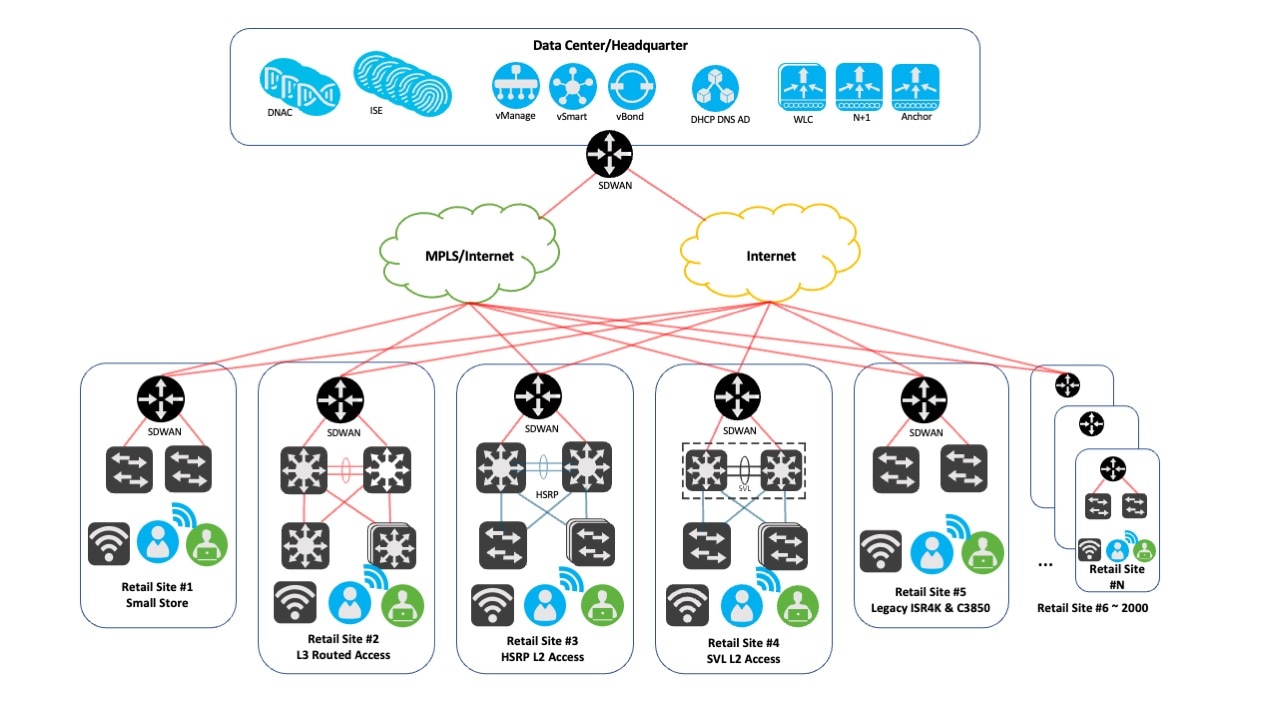
The following figure shows the logical topology of the retail vertical solution test bed.
 Note |
If you are viewing this guide on cisco.com, click any of its figures to view the full-sized version. |
Site #1 represents the small retail site deployment, where a Cisco Catalyst 9300 switch is used as a Layer 2 access switch. A Catalyst 8300 is used for routing and Cisco SD-WAN services.
Site #2 represents the medium to super large retail site deployment, where multiple Catalyst 9300 switches are used as Layer 3 routed access switches. A Catalyst 9300/9500 switch pair is used in the distribution layer. A Catalyst 8300 is used for Cisco SD-WAN services.
Site #3 represents the super large retail site or distribution center/warehouse deployment, where multiple Catalyst 9300 switches (and stacks) are used as Layer 2 access switches. A Catalyst 9300/9500 switch pair is used in the distribution layer. HSRP is configured for load balancing. A Catalyst 8300 is used for Cisco SD-WAN services.
Site #4 represents the medium to super large retail site deployment, where multiple Catalyst 9300 switches (and stacks) are used as Layer 2 access switches. A Catalyst 9500 switch SVL pair is used in the distribution layer. A Catalyst 8300 is used for Cisco SD-WAN services.
Site #5 represents the legacy retail site deployment, where Catalyst 3850 switches are used as Layer 2 access switches. A Cisco ISR 4000 is used for routing and Cisco SD-WAN services.
Sites #6 - 2000 are simulated by tools. Devices and APs are assigned for each site.
Scale
Solution test verified the scale numbers listed in the following table. For the software and hardware capacity, see the Cisco DNA Center Data Sheet.
| Attribute | Scale Numbers |
|---|---|
|
AP |
10,000 (5000 APs/wireless controller) distributed across 2000 sites |
|
Network devices |
3000 |
|
Wireless endpoints |
300,000 |
|
Network profiles |
10 |
|
Retail sites |
2000 |
|
Buildings and floors |
4000 |
|
SSIDs |
20 |
|
WLCs |
7 (4 for two wireless controller SSO pairs, 2 for a N+1 HA wireless controller, and 1 for a guest anchor) |
Solution Key Notes
This section describes technical notes that are useful for deploying the retail vertical profile.
Wireless FlexConnect at Remote Sites
The FlexConnect solution enables retail operations to configure and control APs in remote sites from the corporate headquarter through a WAN link without deploying a controller at each site. The FlexConnect APs can also switch client data traffic locally and perform client authentication locally when the connection to the controller is lost. When connected to the controller, these APs can send traffic back to the controller and also perform local authentication.
The controller software has a more robust fault tolerance method to FlexConnect APs. Whenever a FlexConnect AP disassociates from a controller, it moves to the standalone mode. The connection between the clients and the FlexConnect APs is maintained, providing the client seamless connectivity. When both the AP and controller have the same configuration, the connection between the clients and APs is maintained.
Procedure
|
Step 1 |
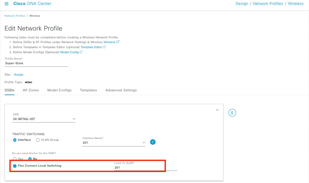
To configure FlexConnect on Cisco DNA Center, do the following:
|
|
Step 2 |
To create Flex Groups, choose . 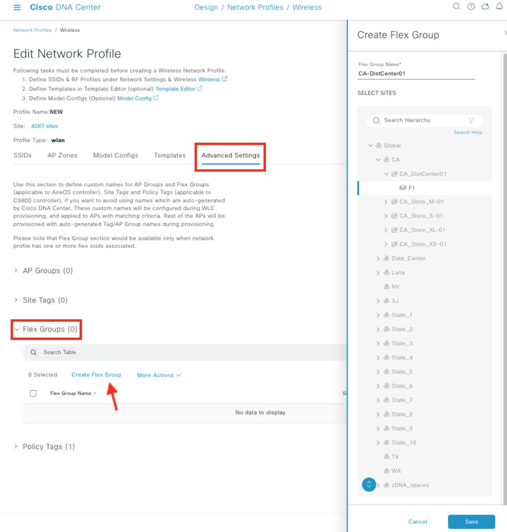
|
|
Step 3 |
To configure FlexConnect local authentication, choose . 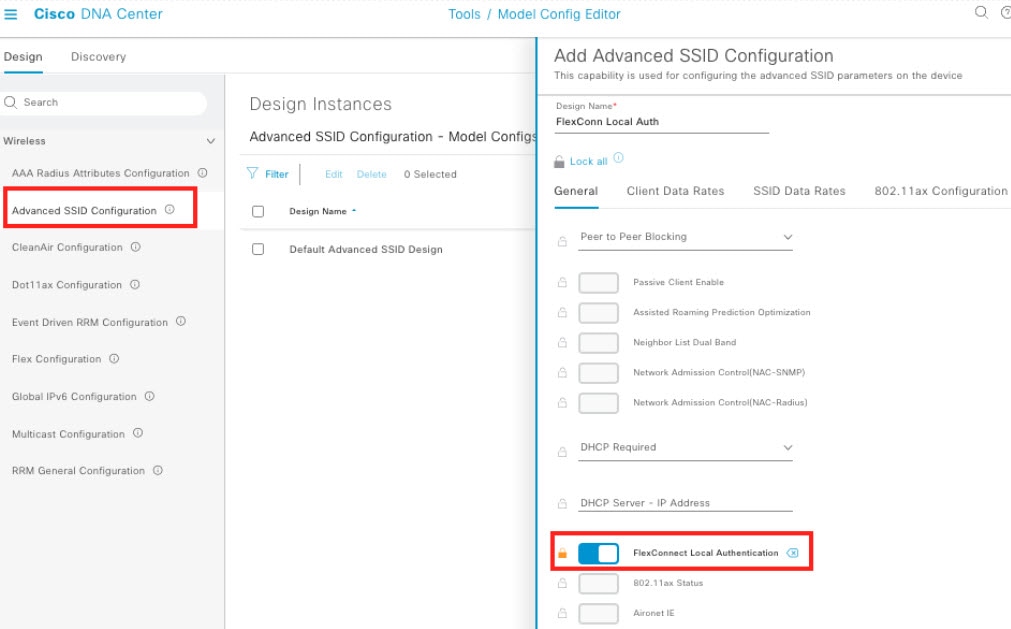
|
IP Address Overlapping
In FlexConnect deployments, by default, if you reuse the same IP subnets at separate locations, wireless controllers detect multiple client sessions with the same IP address as IP THEFT. As a result, clients are blocklisted.
In the FlexConnect Deployment feature, the Overlapping Client IP Address capability allows you to overlap IP addresses across multiple FlexConnect sites while keeping all the supported functionalities in FlexConnect deployments. Network administrators can use a cookie-cutter configuration across sites with the same subnets to simplify management and integrate separate networks without concern of IP addresses overlapping.
You can enable IP address overlap on Cisco DNA Center with the following procedure.
Procedure
|
Step 1 |
To create a model configuration, do the following:
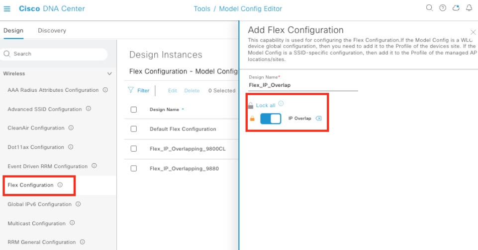
|
|
Step 2 |
To add the model configuration to network profiles, do the following:
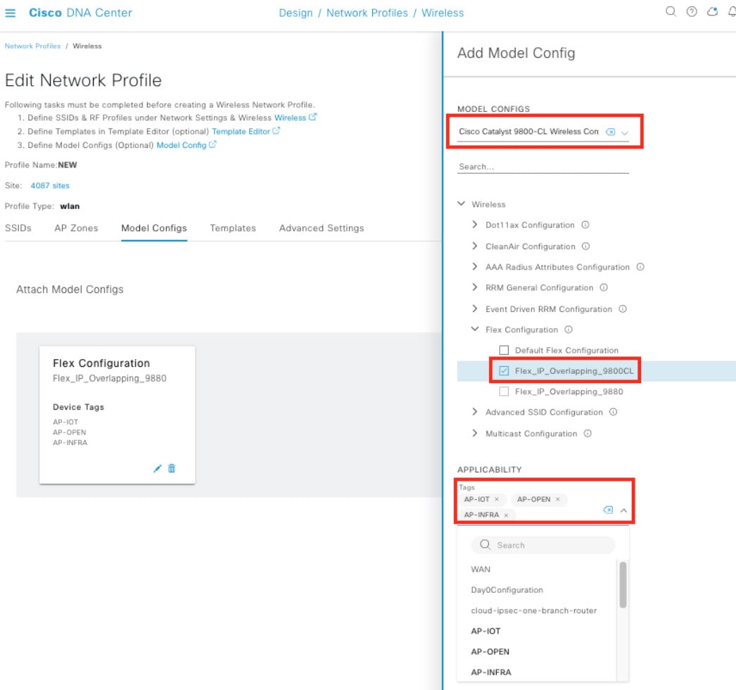
|
Remote Location Guest Access
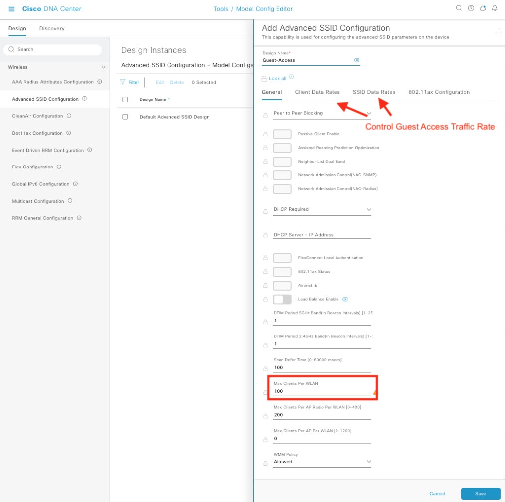
For remote stores, guest authentication cannot be done on a FlexConnect local authentication-enabled wireless LAN (WLAN). Instead, for guest access, a WLAN is set up with a centrally-managed SSID tunneled back to a wireless controller in the DMZ zone. When associating a guest SSID to a profile on Cisco DNA Center, if an anchor wireless controller is checked, the Flex Connect Local Switching option is not available.
You can configure the max number of clients and max client data rate on a guest WLAN by choosing . Then attach the model configuration to the network profiles as the following figure displays.
Local DHCP Server
In a typical store site setup, a FlexConnect AP is linked to the local switch through a trunk interface with a native VLAN, and DHCP pools are set up on the local switch. The FlexConnect AP gets its IP address from the first DHCP pool (NATIVE) while the other DHCP pools (LOCAL-SWITCH) are reserved for wireless endpoints when they connect to a locally-switched WLAN.
Location Services by Cisco Spaces
Cisco Spaces is a location services platform that runs on the cloud and offers real-time location data and analytics for various industries. By using wireless APs and other network devices, the platform gathers data on individuals' movement and assets in physical spaces. Then this data is analyzed to generate insights into user behavior, traffic patterns, and other significant metrics. The Cisco Spaces Connector 2.3.4 was verified in a solution test.
Currently, the Cisco Spaces Connector 3.0 does not support multiple interfaces.
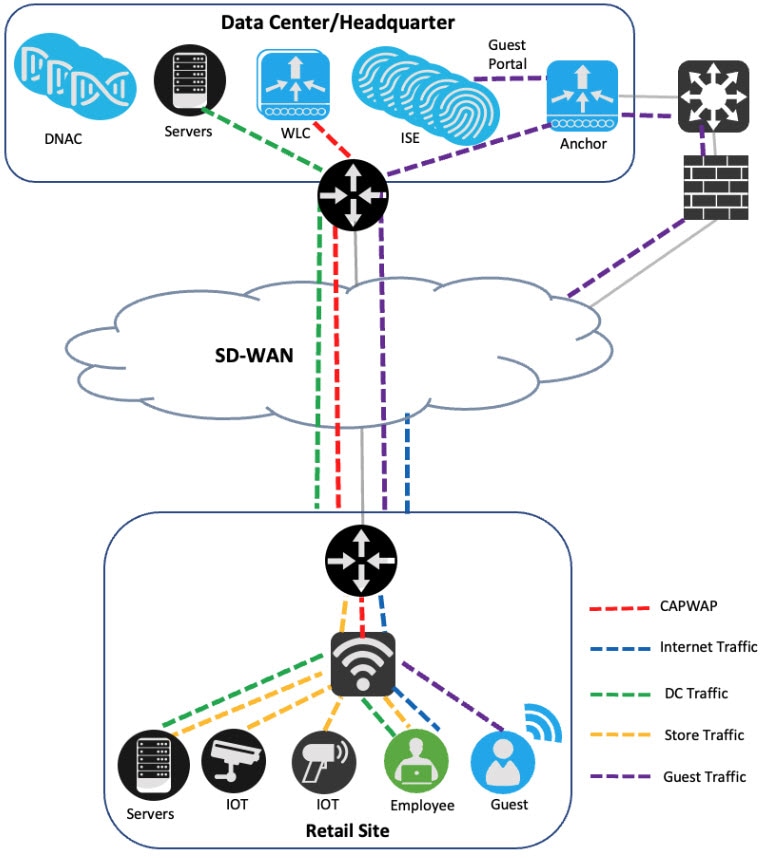
Remote Site Traffic Flow
When using the FlexConnect wireless deployment at remote store and warehouse sites, the traffic generated by business wireless endpoints is locally switched. AP Control and Provisioning of Wireless Access Points (CAPWAP) traffic and guest access are transmitted to the central wireless controller. Any store-to-store traffic is obstructed by the Cisco SD-WAN policy or TrustSec. Additionally, traffic to the internet and cloud-based applications can exit directly through the local internet link instead of being redirected to the data center. This can be achieved through the Cisco SD-WAN Direct Internet Access policies.
Cisco Intelligent Capture
Cisco Intelligent Capture (iCAP) offers real-time technical insights into various wireless metrics from the viewpoint of both the client and AP. iCAP provides a direct communication link between Cisco DNA Center and APs, enabling each of the APs to communicate with Cisco DNA Center directly. This channel allows Cisco DNA Center to receive packet capture (PCAP) data, AP and client statistics, and spectrum data, which may not be available through wireless controllers. With iCAP, even the most challenging wireless issues can be resolved effortlessly.
To integrate iCAP with Cisco DNA Center, see the Cisco Intelligent Capture Deployment Guide.
Ekahau Integration
Ekahau can integrate with Cisco DNA Center through Ekahau AI Pro. This integration allows network engineers to design, plan, and optimize Wi-Fi networks using Ekahau AI Pro. After, they can export the design to Cisco DNA Center for deployment.
With this integration, Ekahau AI Pro can import network topology information and client information from Cisco DNA Center, allowing network engineers to design their Wi-Fi network based on real network data. Then Ekahau AI Pro can export the design to Cisco DNA Center, where the network can be deployed and managed.
Also, this integration enables Ekahau AI Pro to receive network configuration information from Cisco DNA Center, such as the locations of APs and their associated configuration settings. This allows network engineers to easily monitor the wireless network and identify areas that require optimization.
Overall, the Ekahau AI Pro integration with Cisco DNA Center provides network engineers with a streamlined, efficient process for designing, planning, and optimizing Wi-Fi networks.
If you are using Cisco DNA Center-exported Ekahau projects, the schema version 1.7 used in Ekahau AI Pro Version 11.1.0 and later is not compatible. Although Ekahau AI Pro doesn't provide a support statement, you can use the earlier Version 11.0.2.219, which is compatible with the exported projects. We recommend using the supported version until the latest schema version is supported.
Latency Impact
Latency can have a significant impact on retail operations and affect customer satisfaction. To ensure optimal performance, the round-trip latency between the AP and controller must not exceed 300 ms, and CAPWAP control packets should have priority over all other traffic. When it isn't possible to achieve the 300-ms round-trip latency, a practical solution is to configure the AP to perform local authentication.
Onboard Devices with Plug and Play
Plug and Play provisioning provides a way to automatically and remotely provision and onboard network devices with minimal network administrator and field personnel involvement.
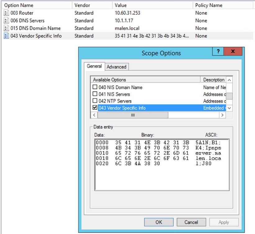
If the Cisco DNA Center system certificate is issued by an external CA server, its common name (CN) should include the pnpserver hostname. Before starting Plug and Play, the DHCP pool should contain the option 43 string with the FQDN, B1, DNS server, and domain name.
See the following sample DHCP pool configuration on a Cisco switch.
ip dhcp pool PnP_Pool
network 214.2.64.0255.255.255.0
default-router 214.2.64.1
option 43 ascii "5A1D;B1;K4;Ipnpserver.<domain-name>;J80;"
domain-name <domain-name>
dns-server <dns-server>
A sample DHCP pool option configuration on a Windows Server is as follows:
For more details, see the Cisco DNA Center User Guide, Release 2.3.3.
Configure Access Points Workflow
To prevent Cisco DNA Center from running out of memory (OOM), we recommend that you limit the selection of APs to 2000 at a time when using the Configure Access Points workflow.
 Feedback