Solution Overview
Catalyst Center on ESXi is a new form factor that supports the Catalyst Center application in a virtual environment. The virtual form factor helps customers rapidly deploy and operate Catalyst Center.
Catalyst Center on ESXi offers the same centralized and intuitive management as the Catalyst Center platform.
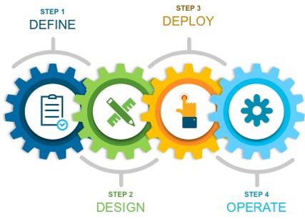
This guide provides technical guidance to design, deploy, and operate Catalyst Center on ESXi.
This guide contains the following main sections:
-
Solution Overview presents a high-level overview of Catalyst Center on ESXi.
-
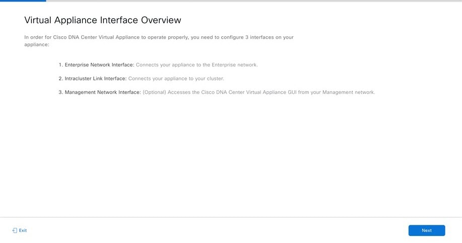
Design and Prerequisites discusses the VMware ESXi prerequisites to deploy Catalyst Center on ESXi; requirements for creating the virtual appliance (VA); supported scale, latency, and bandwidth; launcher tool requirements; and how to set up network interfaces, NTP, and DNS servers for deployment of Catalyst Center on ESXi. The launcher tool is an internal Cisco utility used to deploy and configure the VA.
-
Deploy Catalyst Center on ESXi discusses deployment of Catalyst Center on ESXi, different configuration methods, postdeployment configurations, configuration of authentication and policy servers, configuration of high availability (HA) using vSphere, backup and restore using local disk and NFS support, managing applications and software, and managing different user roles within Catalyst Center.
-
Operation: Monitoring and Troubleshooting discusses how to monitor and troubleshoot the Catalyst Center VA deployed on ESXi.
The audience for this guide includes network design engineers and network operations personnel who don't have a Catalyst Center appliance but want to manage their networks with Catalyst Center.
Design and Prerequisites
This section explains the design and prerequisites for Catalyst Center on ESXi:
-
Prerequisites for deployment
-
Supported scale
-
Certificate management for Catalyst Center on ESXi
-
Launcher requirements for configuring Catalyst Center on ESXi
-
Preparation of VMware vSphere; reservation of the enterprise interface; and preparation of DNS, NTP, and proxy servers
-
Limitations and restrictions
-
Feature support
Deployment Requirements
The following requirements must be met in order to successfully deploy a Catalyst Center on ESXi virtual appliance. For performance tips that cover the most performance-critical areas of VMware vSphere, see:
-
VMware vSphere Client 7.0: Performance Best Practices for VMware vSphere 7.0 (PDF)
-
VMware vSphere Client 8.0: Performance Best Practices for VMware vSphere 8.0 (PDF)
Virtual Machine Minimum Requirements
| Feature | Description |
|---|---|
|
Virtualization platform and hypervisor |
VMware vSphere (which includes ESXi and vCenter Server) 7.0.x or later, including all patches |
|
Processors |
Intel 2.1-GHz and later CPU 32 vCPUs with 64-GHz reservation must be dedicated to the VM |
|
Memory |
256-GB DRAM with 256-GB reservation must be dedicated to the VM |
|
Storage |
3-TB solid-state drive (SSD) If you plan to create backups of your virtual appliance, also reserve additional datastore space. For information, see "Backup Server Requirements" in the Cisco Catalyst Center on ESXi Administrator Guide. |
|
I/O Bandwidth |
180 MB/sec |
|
Input/output operations per second (IOPS) rate |
2000-2500, with less than 5 ms of I/O completion latency |
|
Latency |
Catalyst Center on ESXi to network device connectivity: 200 ms |
Scale Numbers
The following tables list the number of devices and site elements that Catalyst Center on ESXi supports.
| Network Component | Maximum Number Supported |
|---|---|
|
Access Points |
4000 |
|
Devices |
1000 |
|
Endpoints |
25,000 |
|
Site Elements |
2500 |
| Network Component | Maximum Number Supported |
|---|---|
|
Endpoints |
25,000 |
|
Devices |
2000 |
|
Access Points |
3000 |
|
Site Elements |
2500 |
|
Per-Fabric Site Scale |
|
|
Fabric Nodes |
500 |
|
VNs |
64 |
|
IP Pools |
100 |
For both nonfabric and fabric deployments, up to 10 concurrent user connections are supported for network admins to log in to Catalyst Center on ESXi.
Catalyst Center VA Launcher Requirements
If you plan to use the CC VA Launcher to deploy and configure a virtual appliance, the following requirements must be met by the machine on which you'll run the app:
| Feature | Description |
|---|---|
|
RAM |
1 GB |
|
Storage |
|
|
Supported operating systems |
|
|
Sleep setting |
Configure the machine to not go to sleep. |
In addition to these requirements, do the following:
-
Ensure that the user who will run the CC VA Launcher has the privileges necessary to deploy the virtual appliance's OVA file and modify the appliance's virtual machine settings.
-
For the system you'll run the app on, configure its HTTP/network proxy settings (if applicable).
Supported Browsers
-
Mozilla Firefox, version 65 or later
-
Google Chrome, version 72 or later
Topology
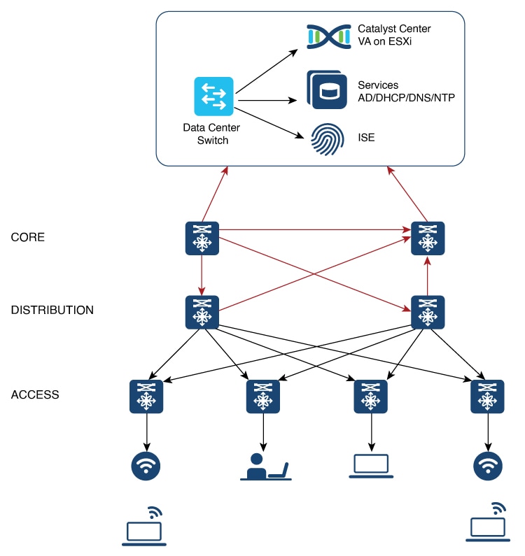
Catalyst Center ESXi is located in the on-premises data center.
Prepare for Deployment
To prepare for the deployment of a Catalyst Center on ESXi virtual appliance, you'll need to complete the following tasks:
Install VMware vSphere
To run, Catalyst Center on ESXi requires VMware vSphere (which includes ESXi and vCenter Server) 7.0.x or later, including all patches. Click here to access an overview of the VMware vSphere installation and setup process. After you have installed VMware vSphere, confirm that it can be reached from the computer that you will use to deploy the virtual appliance's OVA file.
Reserve Enterprise Interface
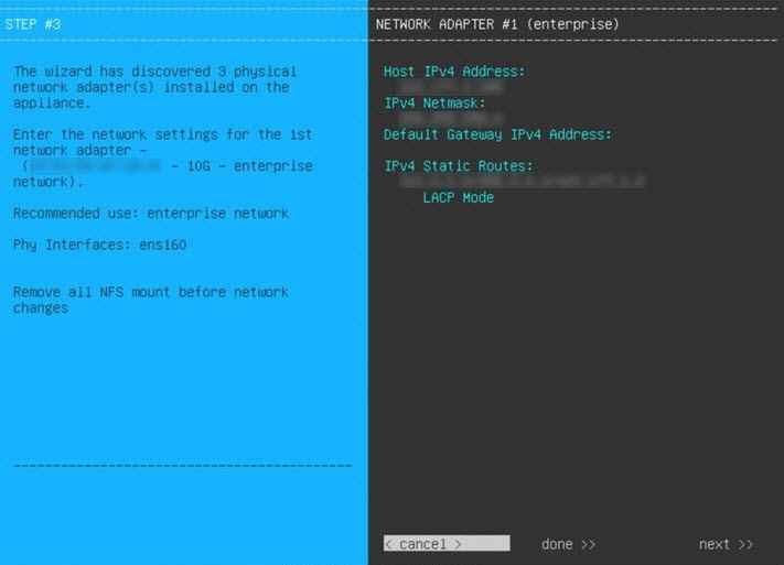
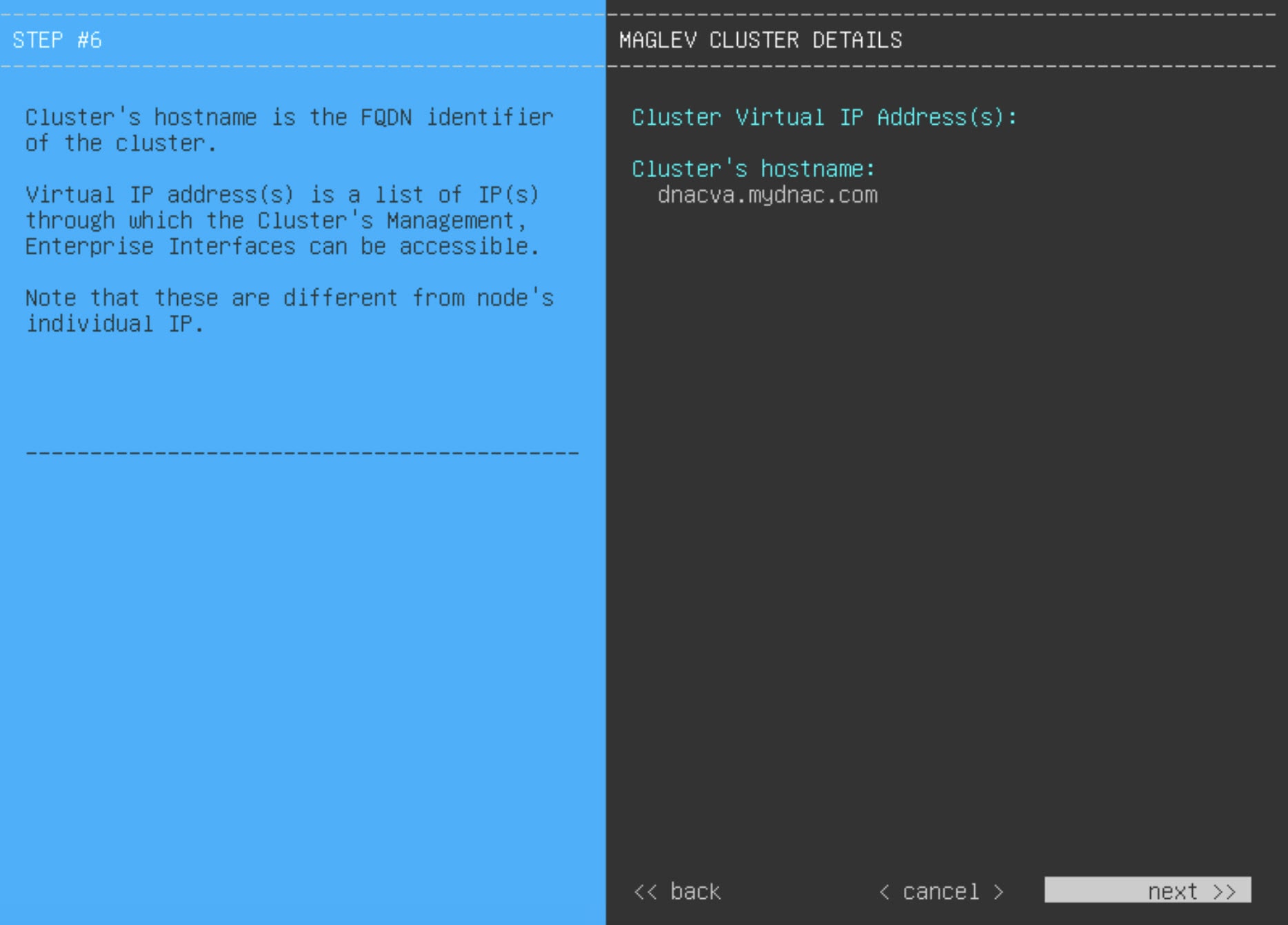
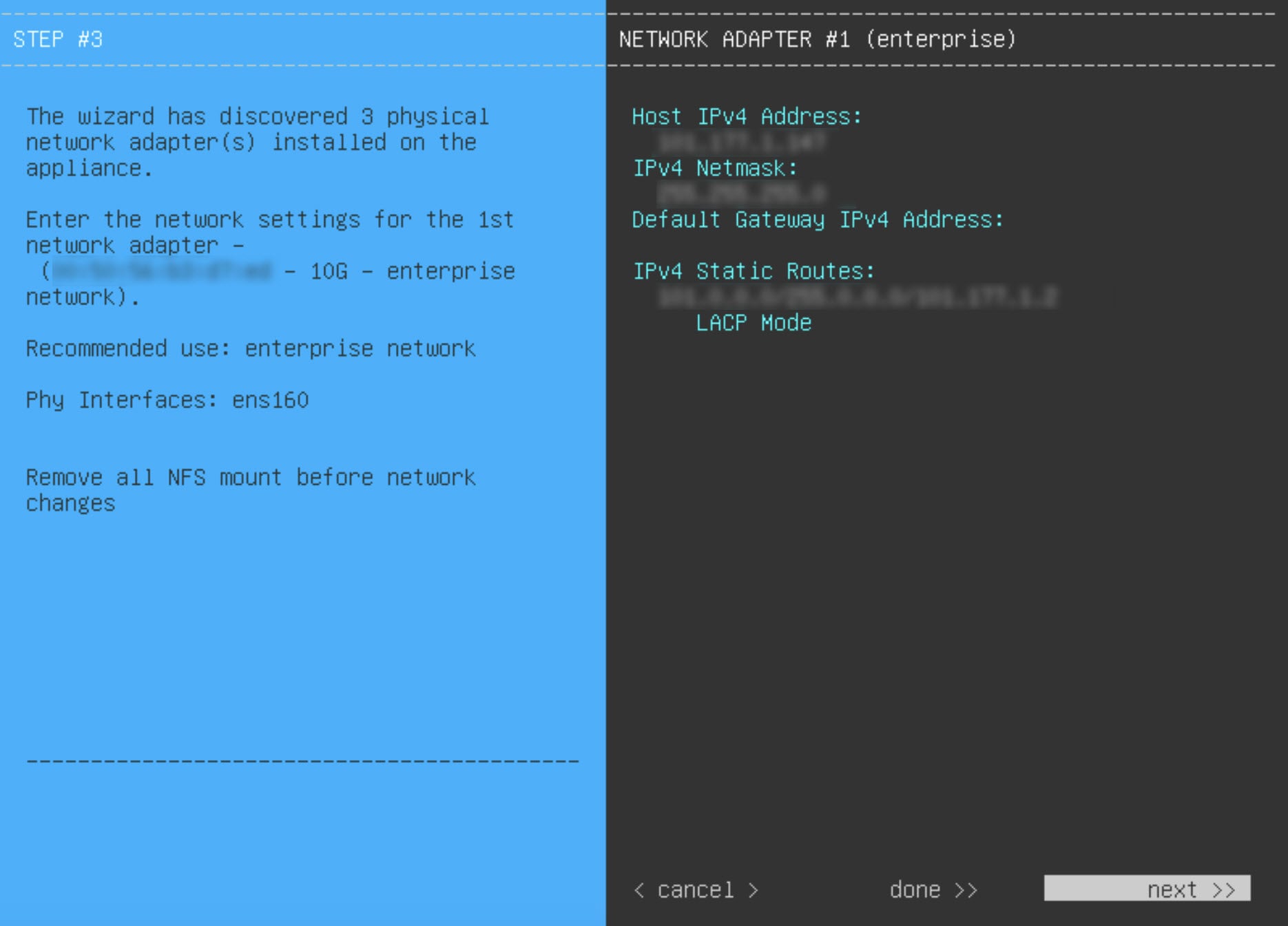
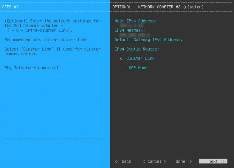
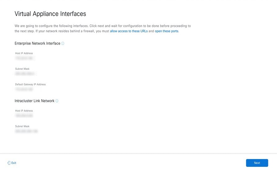
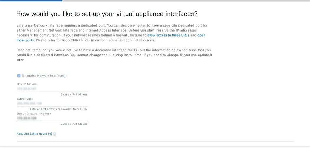
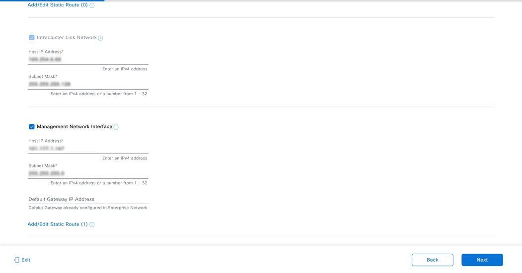
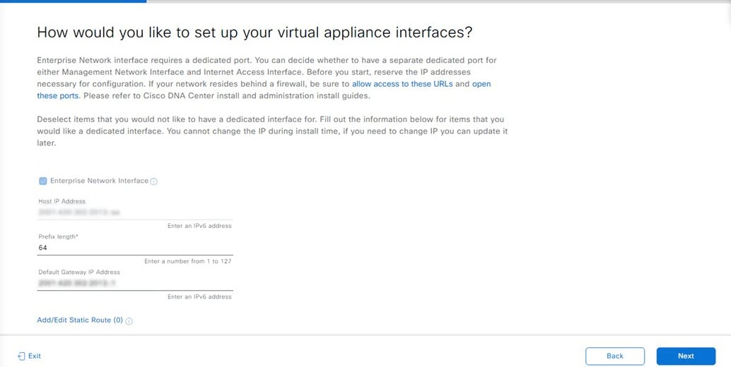
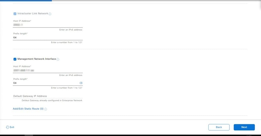
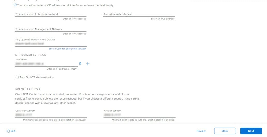
Before you set up the virtual appliance, ensure that you reserve one 1-Gbps/10-Gbps Enterprise interface to connect to and communicate with your enterprise network. Write down the IP address for this interface, because you'll need to enter it during appliance configuration.
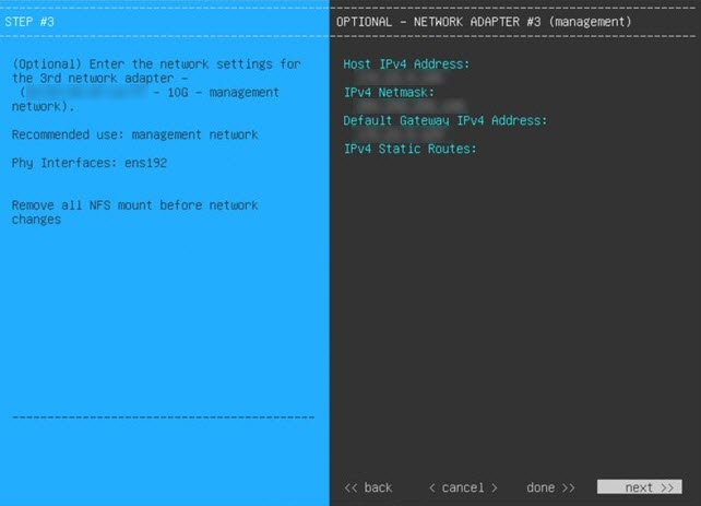
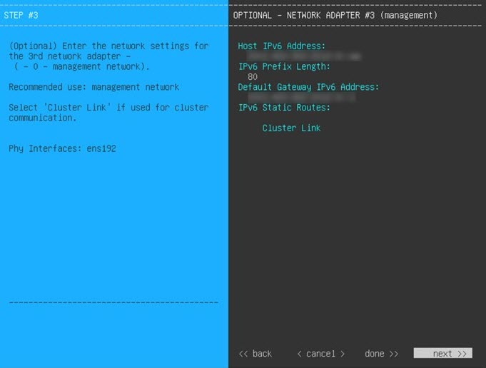
Optionally, you can also reserve one 1-Gbps/10-Gbps Management network interface to access the Catalyst Center on ESXi GUI. Write down this interface's IP address as well if you plan to configure it.
Note the following points:
-
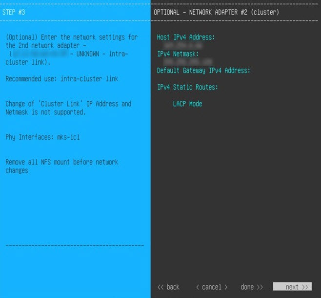
The intracluster interface's IP address is predefined, so you won't need to enter it when you complete either the Maglev Configuration wizard with default mode selected or the browser-based Install Configuration wizard.
-
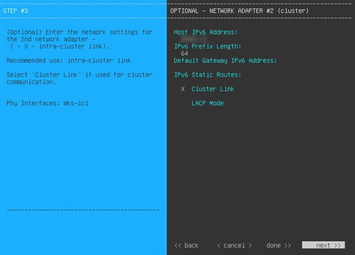
Catalyst Center on ESXi supports the configuration of one additional interface for use by the virtual appliance. If you do so, make sure that you choose VMXNET from the Adapter Type drop-down list. Otherwise, appliance configuration will not complete successfully. For more information, see the Add a Network Adapter to a Virtual Machine topic in vSphere Virtual Machine Administration.
Import the IdenTrust Certificate Chain
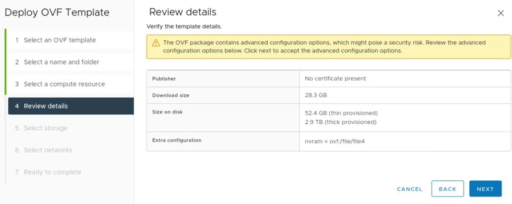
The Catalyst Center on ESXi OVA file is signed with an IdenTrust CA certificate, which is not included in VMware's default truststore. As a result, the Deploy OVF Template wizard's Review details page will indicate that you are using an invalid certificate while completing the wizard. You can prevent this by importing the IdenTrust certificate chain to the host or cluster on which you want to deploy the OVA file.
Procedure
|
Step 1 |
On the VMware ESXi host or cluster where your virtual appliance will reside, download trustidevcodesigning5.pem from the same location that Cisco specified to download the Catalyst Center on ESXi OVA file. |
|
Step 2 |
Unzip this file. |
|
Step 3 |
Log in to the vSphere Web Client. |
|
Step 4 |
Choose . |
|
Step 5 |
In the Trusted Root Certificates field, click Add. |
|
Step 6 |
In the Add Trusted Root dialog box, click Browse. |
|
Step 7 |
Navigate to and select the certificate chain that you downloaded in Step 1 (trustidevcodesigning5.pem), then click Open. |
|
Step 8 |
Check the Start Root certificate push to vCenter Hosts check box, then click Add. A message indicates that the certificate chain was imported successfully. When you complete the Deploy OVF Template wizard, the Review details page's Publisher field should indicate that you are using a trusted certificate. |
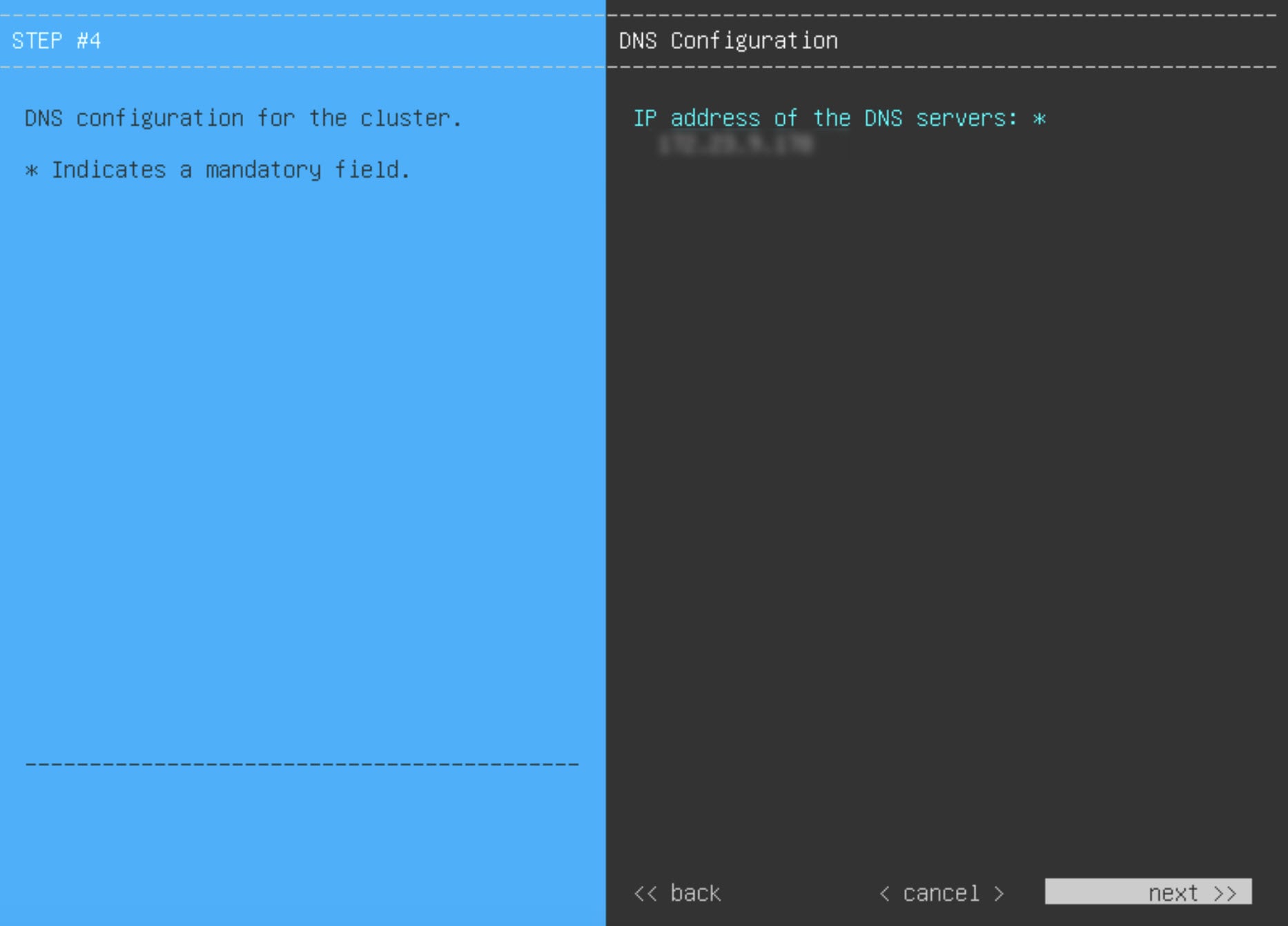
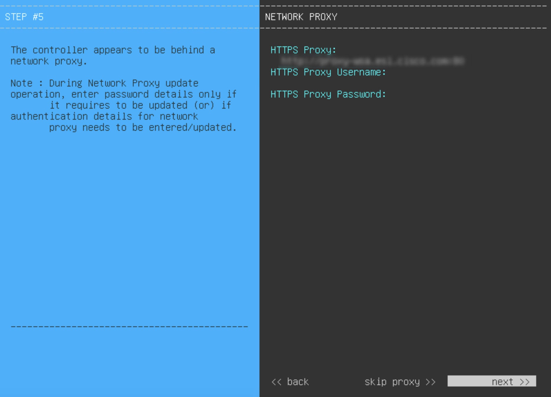
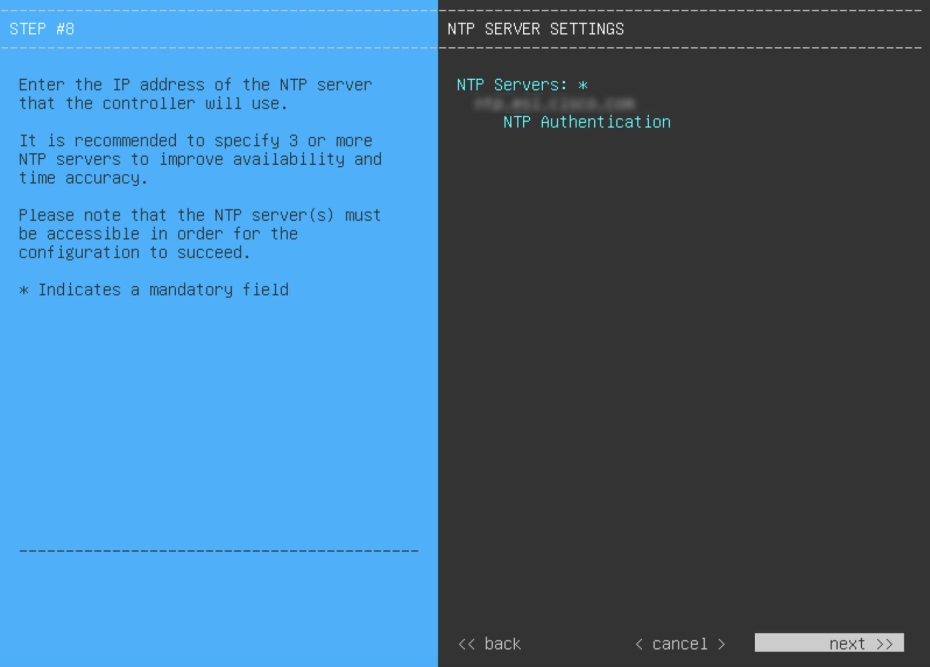
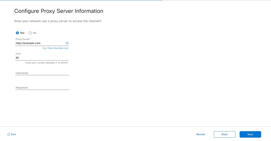
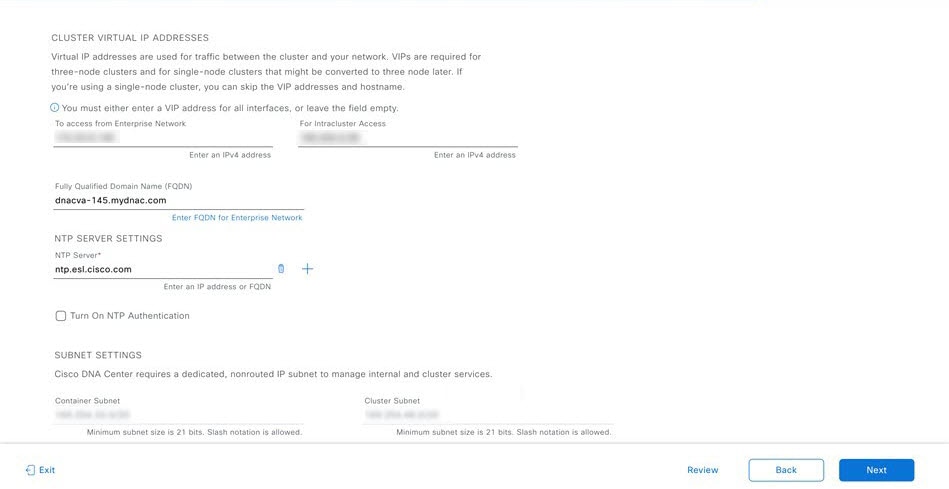
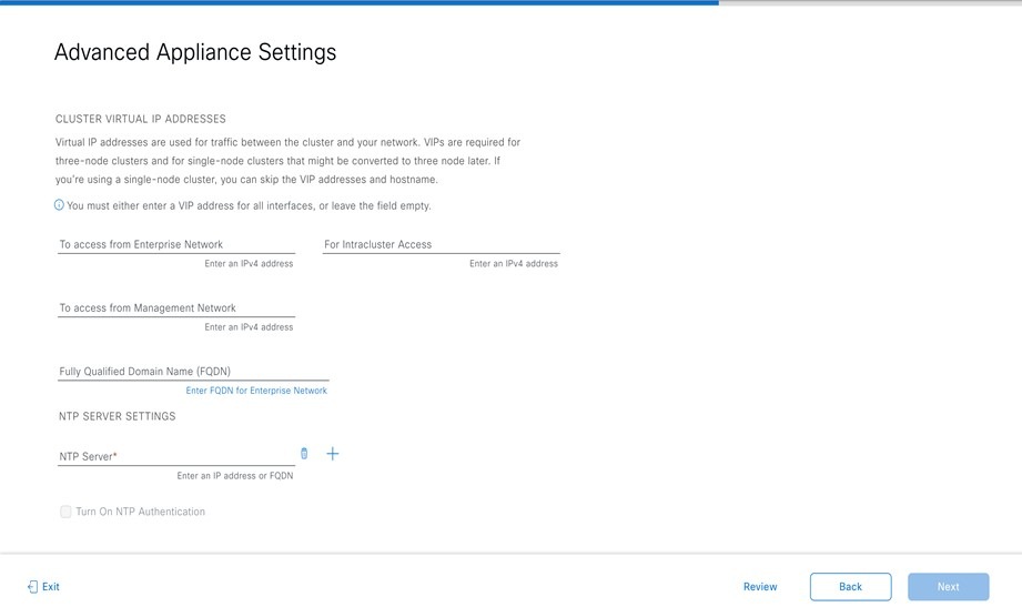
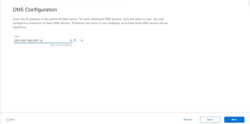
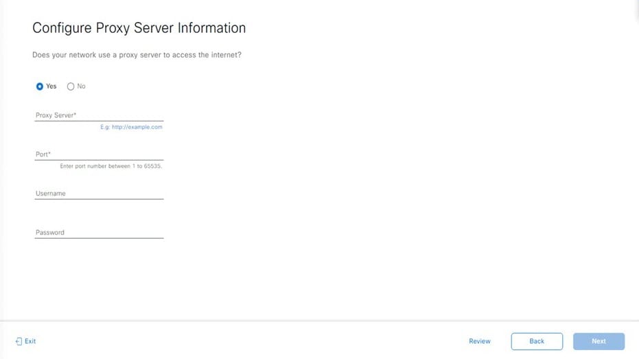
Prepare the DNS, NTP, and Proxy Servers
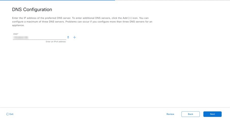
You'll be prompted to specify three items:
-
The Domain Name System (DNS) server that Catalyst Center on ESXi will use to convert domain names to IP addresses.
-
The Network Time Protocol (NTP) server that Catalyst Center on ESXi will use for clock synchronization.
-
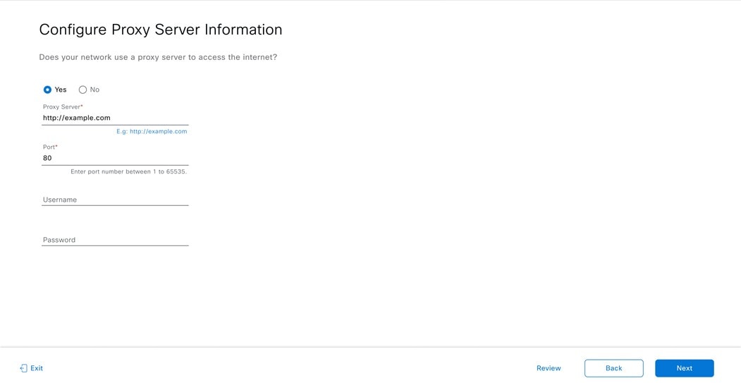
(Optional) The proxy server that Catalyst Center on ESXi will use to access internet-bound URLs.
Before you configure your virtual appliance, do the following:
-
Ensure that the servers you want to use are available and running.
-
For an NTP server, obtain its IP address or hostname. And for a proxy server, collect either its URL or hostname and its login credentials.
Prepare for the Quick Start Workflow
After you create a virtual machine on an ESXi host and configure a Catalyst Center on ESXi virtual appliance, you'll be prompted to complete the Quick Start workflow. By completing this workflow, you'll discover the devices that Catalyst Center on ESXi will manage and enable the collection of telemetry from those devices. To complete this workflow successfully, you'll need to perform the following tasks:
-
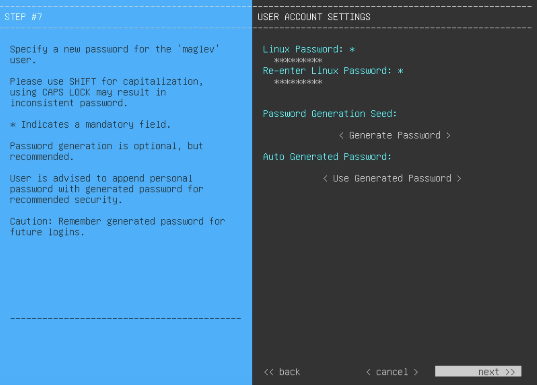
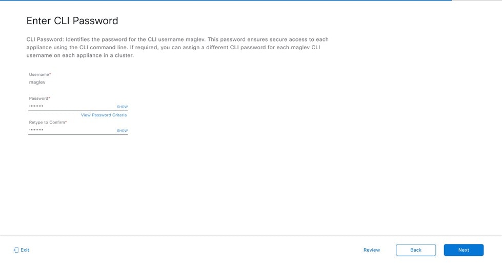
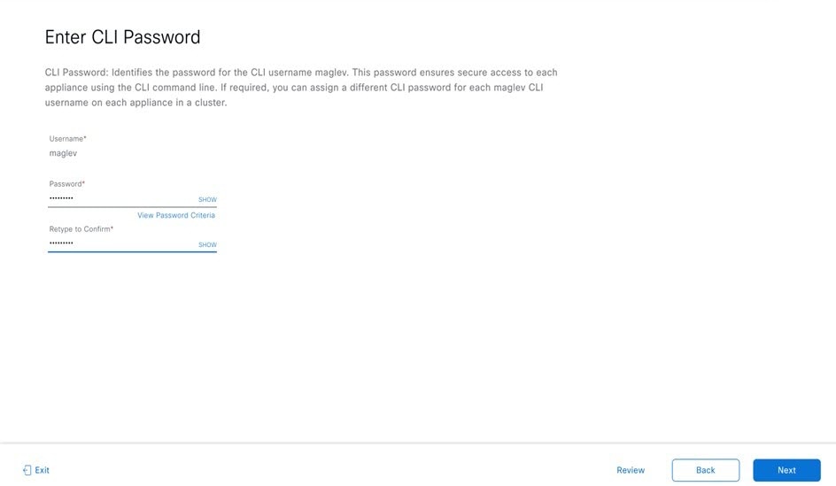
Decide on the username and password for the new admin user you're going to create. The default admin username and password (admin/maglev1@3) should only be used the very first time you log in to Catalyst Center on ESXi.

Important
Changing this password is critical to network security, especially when the people who set up a Catalyst Center on ESXi virtual appliance are not the same people who will serve as its administrators.
-
Obtain the credentials you use to log in to Cisco.com.
-
Identify the users who need access to your system. For these users, define their roles as well as unique passwords and privilege settings.
You have the option to use an IPAM server and Cisco Identity Services Engine (ISE) with your virtual appliance. If you choose to use one or both of them, you'll also need to obtain the relevant URL and login credentials.
Enable Storage Input/Output Control
For the datastore in which you are planning to deploy a virtual appliance, complete the following procedure so the appliance's virtual machine input/out (I/O) is prioritized over other virtual machines when the network is experiencing I/O congestion.
Procedure
|
Step 1 |
In the vSphere Client, navigate to and click the datastore in which you plan to deploy a virtual appliance. |
|
Step 2 |
Click the Configure tab, then click General. |
|
Step 3 |
In the Datastore Capabilities area, click Edit. 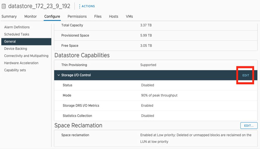 |
|
Step 4 |
In the Configure Storage I/O Control window, do the following: 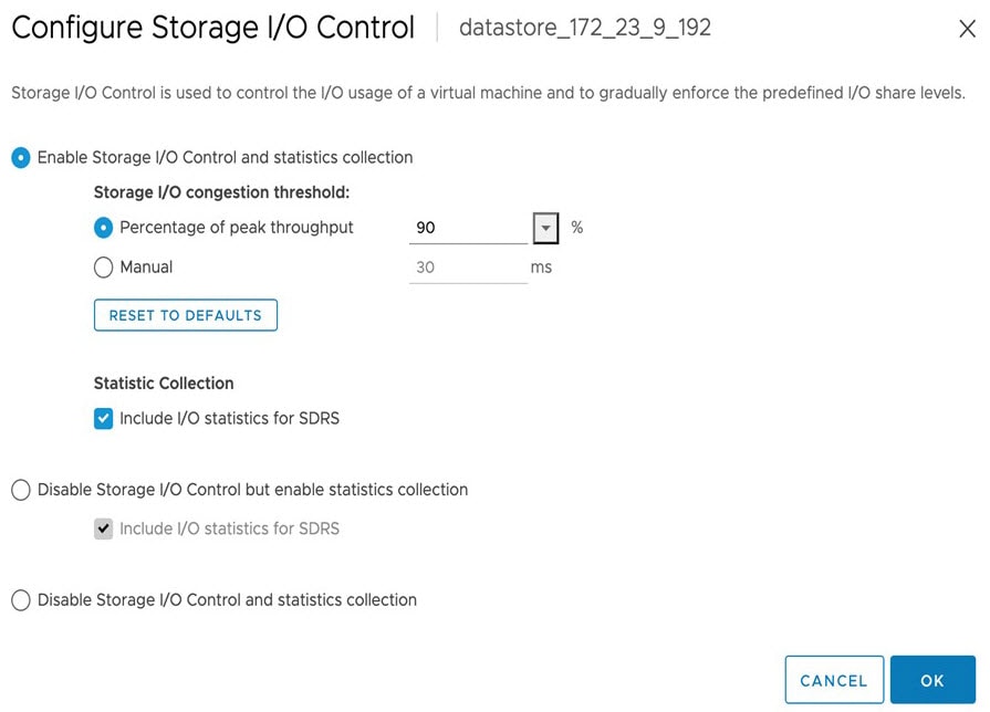 |
|
Step 5 |
Click OK. |
Check HA Admission Control Setting
You cannot connect Catalyst Center on ESXi VMs to create three-node clusters. If you want to enable high availability (HA), you'll need to use VMware vSphere's HA functionality and enable strict admission control to ensure that:
-
A virtual machine cannot be powered on if it will result in the violation of availability constraints.
-
Configured failover capacity limits are enforced.
-
HA operates as expected during a failover.
For more information, in the Cisco Catalyst Center on ESXi Administrator Guide, see the "High Availability" section in the "Configure System Settings" chapter.
Limitations and Restrictions
Catalyst Center on ESXi has the following limitations and restrictions:
-
Unlike the Catalyst Center platform, you cannot connect VMs to create three-node clusters. To achieve high availability, you need to use VMware vSphere. For more information, in the Cisco Catalyst Center on ESXi Administrator Guide, see the "High Availability" section in the "Configure System Settings" chapter.
-
Catalyst Center on ESXi does not support the following VMware vSphere features:
-
Fault tolerance
-
Suspending and resuming VMs
-
Cloning VMs
-
Snapshot (as backup)
-
NIC bonding
-
Features Support
Catalyst Center on ESXi supports all of the features that Catalyst Center supports, except for the following features:
-
Automation: Cisco Wide Area Bonjour application, Cisco vManage for SD-WAN, Cisco DNA Traffic Telemetry Appliance, Cisco Secure Network Analytics.
-
Wireless: Cisco User-Defined Network (UDN), Cisco Umbrella.
-
Assurance: Sensor.
-
System Workflows: Backup and Restore using VMware vSphere Client snapshot function, Backup and Restore from Catalyst Center hardware appliance to Catalyst Center on ESXi virtual appliance.
-
Diagnostics Center: Validation Tool under .
-
Setting Page: Authentication API Encryption.
-
Security Policy Access (SPA): Security Sensor in Endpoint Analytics, Group-Based Policy Analytics (GBPA).
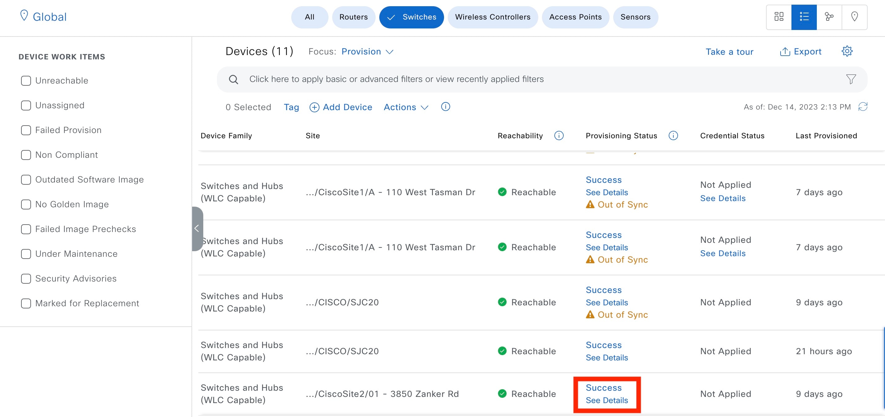
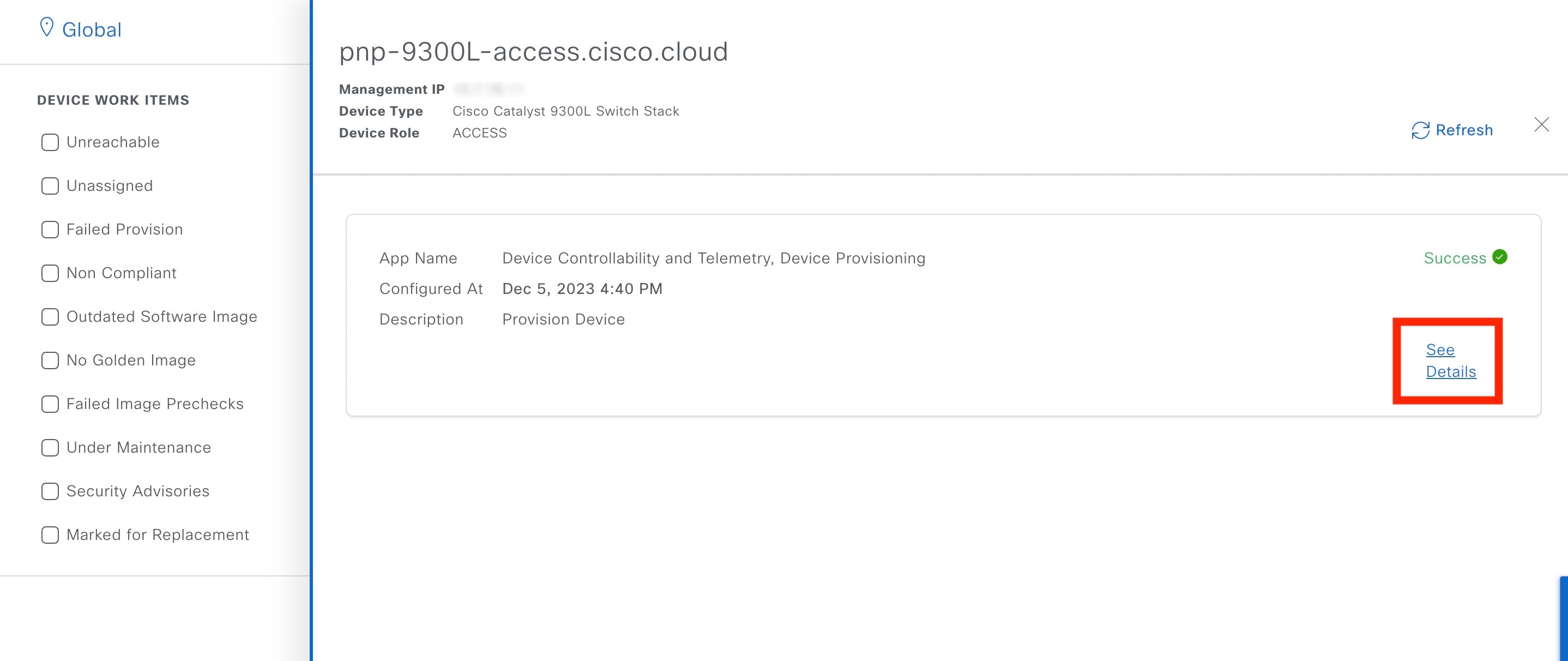
Deploy Catalyst Center on ESXi
The following sections explain how to deploy a VM on Catalyst Center on ESXi, power up the VM, configure the virtual appliance, and complete the Quick Start workflow.
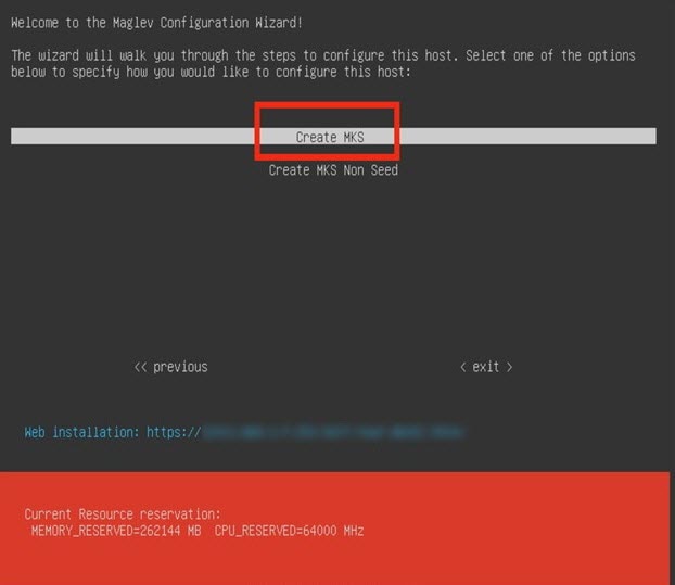
The process to deploy Catalyst Center on ESXi and complete day-1 and day-n operations involves:
-
Create a VM
-
Configure the Catalyst Center on ESXi virtual appliance
-
Complete the Quick Start workflow
-
Postdeployment considerations
-
Configure authentication and policy servers
-
HA using vSphere
-
Backup and restore
-
Software management
-
Manage user access
Create a Virtual Machine
Complete the following procedure to create a virtual machine on the VMware ESXi host or cluster where your virtual appliance will reside.
Procedure
|
Step 1 |
Download the Catalyst Center on ESXi OVA file from the location specified by Cisco. |
||
|
Step 2 |
Log in to the vSphere Web Client. |
||
|
Step 3 |
In the navigation pane, right-click the IP address of host or cluster on which you want to deploy the OVA file and then click Deploy OVF Template. 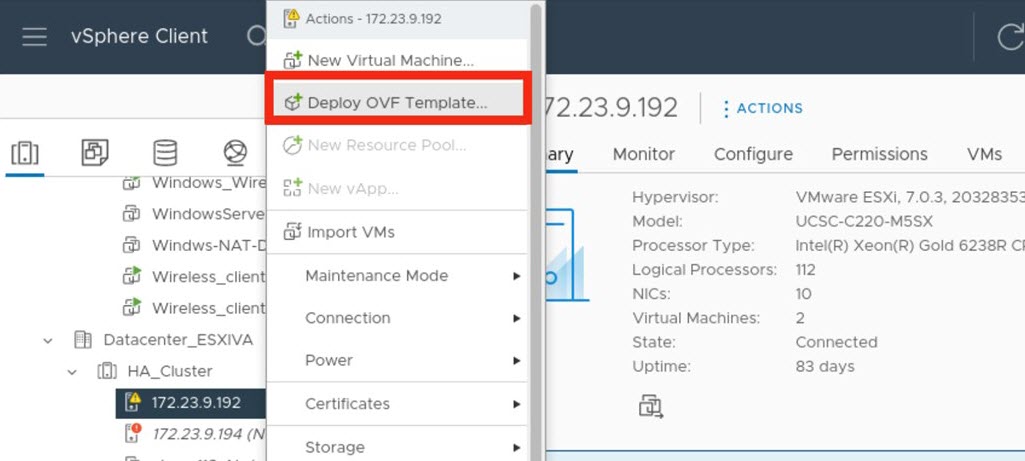
|
||
|
Step 4 |
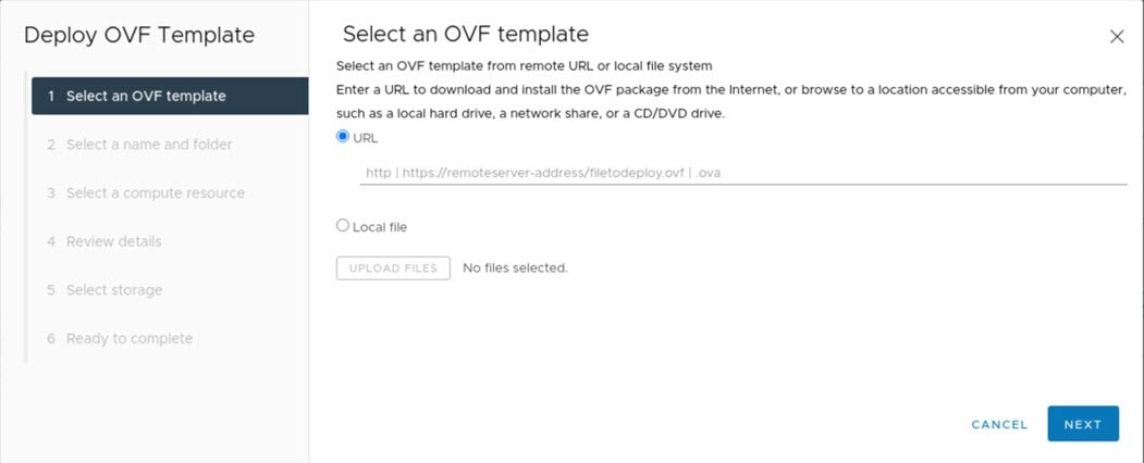
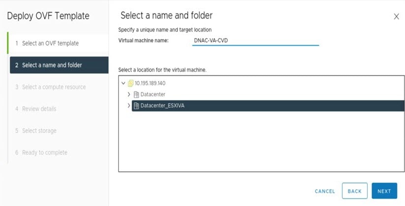
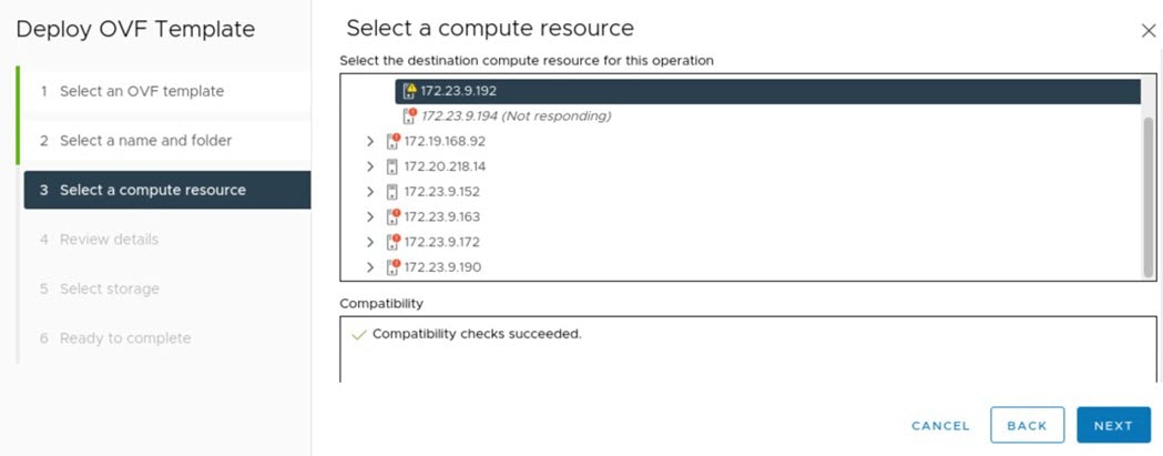
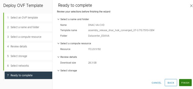
Complete the Deploy OVF Template wizard:
|
Configure an Additional Network Adapter
Complete the following procedure in order to configure an additional network adapter for your virtual appliance, on which the Management interface will reside.
Procedure
|
Step 1 |
Log in to the vSphere Web Client. |
|
Step 2 |
In the navigation pane, right-click the virtual machine you've created, then choose . |
|
Step 3 |
Right-click the virtual machine and then choose . |
|
Step 4 |
With the Virtual Hardware tab selected, click Add New Device and then choose Network Adapter. |
|
Step 5 |
In the New Network field's drop-down list, click Browse. |
|
Step 6 |
In the Select Network dialog box, choose the network that will connect to the virtual appliance's Management interface and then click OK. |
|
Step 7 |
In the Adapter Type field's drop-down list, choose VMXNET3 and then click OK. |
|
Step 8 |
In the navigation pane, right-click the virtual machine, then choose . |
|
Step 9 |
Do one of the following:
|
|
Step 10 |
After Catalyst Center on ESXi comes up, run the Configuration wizard to configure the settings for the Management interface: |
Configure the Management Network (Day 0)
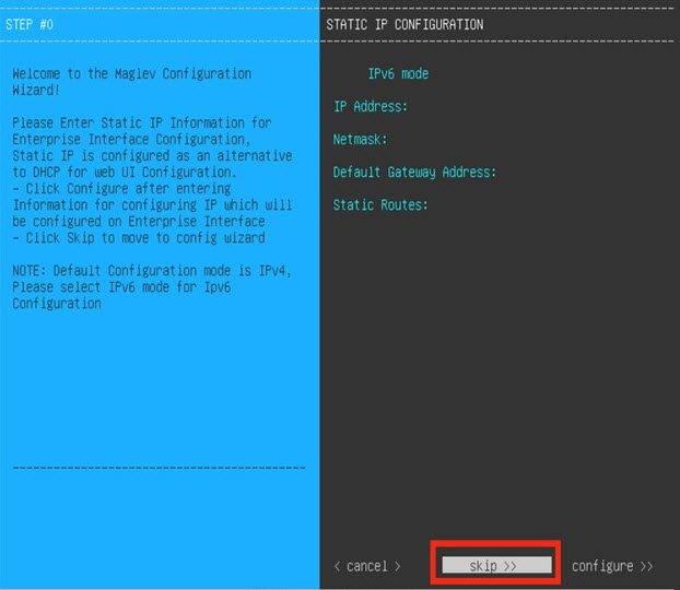
By default, the Catalyst Center OVA comes with only one interface, the Enterprise interface. To add the management network to the appliance, you can add the interface after creating the virtual machine as part of the day-0 operations. Alternately, you can add the interface after the deployment as part of day-n operations, and configure it using the Maglev Configuration wizard.
To add the additional network interface as part of day-0 operations, complete the following procedure.
Procedure
|
Step 1 |
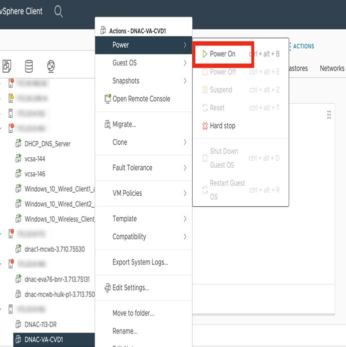
If the Catalyst Center VM is running, do a graceful shutdown. |
|
Step 2 |
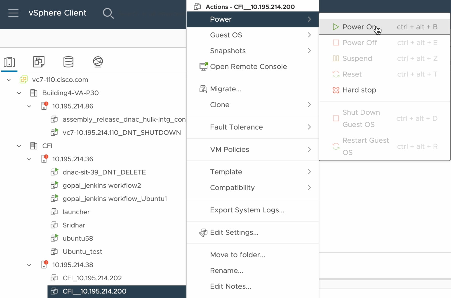
Click the deployed Catalyst Center VM and choose . |
|
Step 3 |
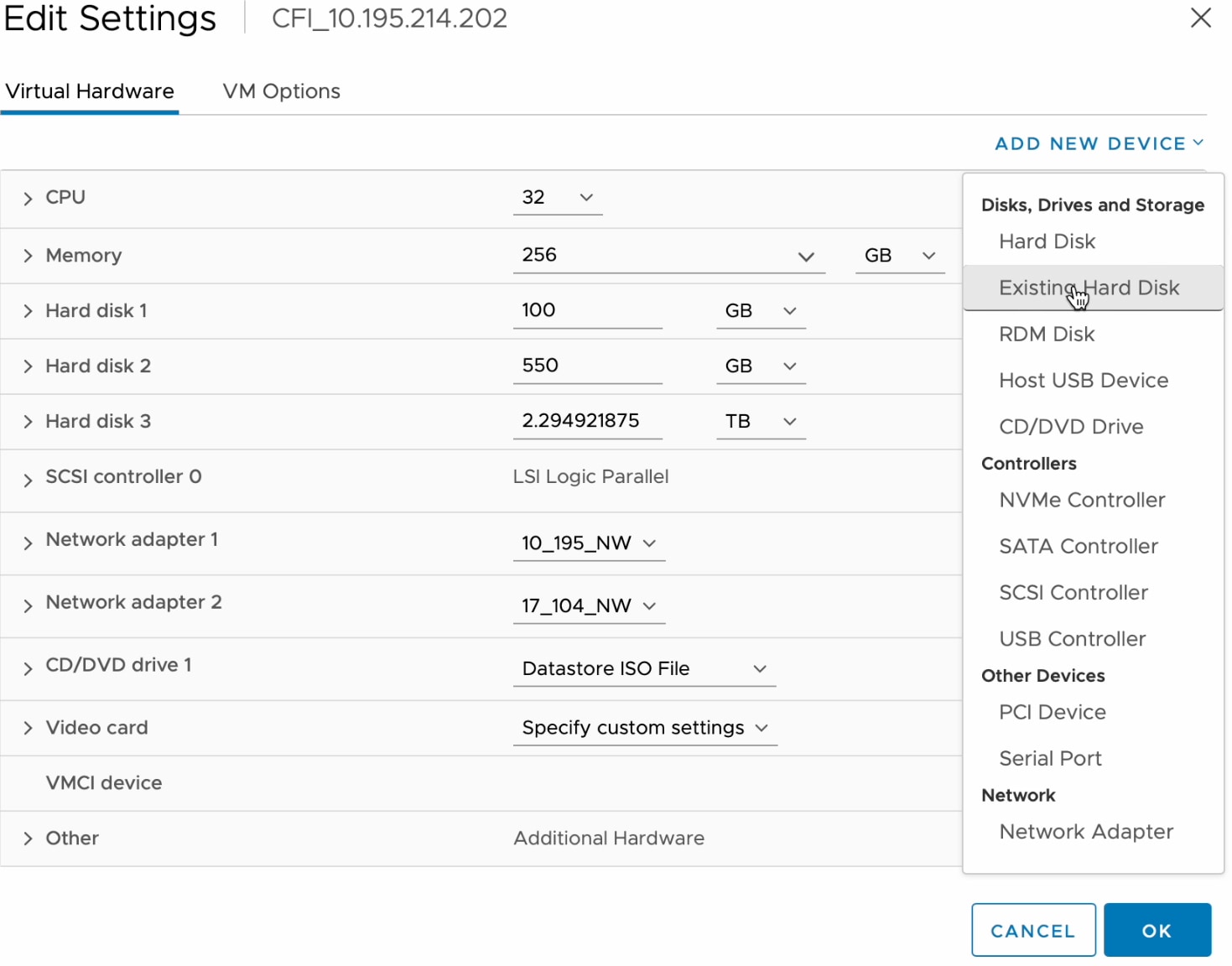
Click ADD NEW DEVICE and choose Network Adapter. After you click Network Adapter, new network adapter is added to the VM. |
|
Step 4 |
Select the network to use for the management network for the newly added adapter. |
|
Step 5 |
For the adapter type, choose VMXNET3 and click OK. The new adapter is added and associated to the selected network.
|
|
Step 6 |
Power on the Catalyst Center VM. |
Configure the Management Network (Day N)
By default, the Catalyst Center OVA comes with only one interface, the Enterprise interface. You can add the management interface after the deployment as part of day-n operations, and configure it using the Maglev Configuration wizard.
This procedure explains how to add the additional network interface as part of day-n operations.
After Catalyst Center is up, open the vSphere UI terminal of the VM and run the sudo maglev-config update command to start the network configuration wizard. The following steps apply to VMs that are already configured with a single NIC and a second NIC is added as part of day-n operations. If you add a second NIC for management before powering on the VM with the preceding method of , complete the following section to configure Catalyst Center using different configuration methods.
Procedure
|
Step 1 |
In the vSphere Client, click the deployed Catalyst Center VM and choose Launch Console. The Maglev wizard opens, where you configure the newly added management interface.
|
|
Step 2 |
At the initial screen, the wizard prompts you to configure the enterprise interface. If it's configured already, click Next. |
|
Step 3 |
At the cluster interface configuration screen, click Next. |
|
Step 4 |
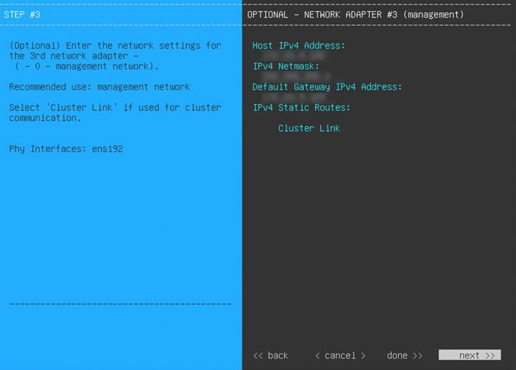
The wizard prompts you to configure the newly added management interface. Enter the appropriate parameters (IP address, subnet mask, and so on) and click Next. |
|
Step 5 |
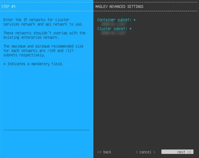
The wizard prompts you to configure network parameters such as proxy, DNS, and NTP servers. Enter the appropriate parameters and click Next. |
|
Step 6 |
Access the Catalyst Center UI by using the configured management network IP. |
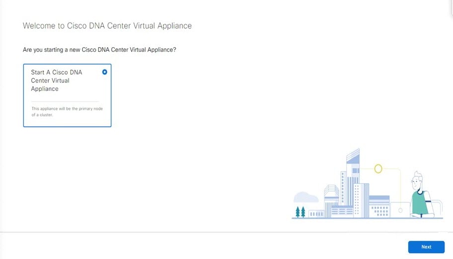
Configure a Catalyst Center on ESXi Virtual Appliance
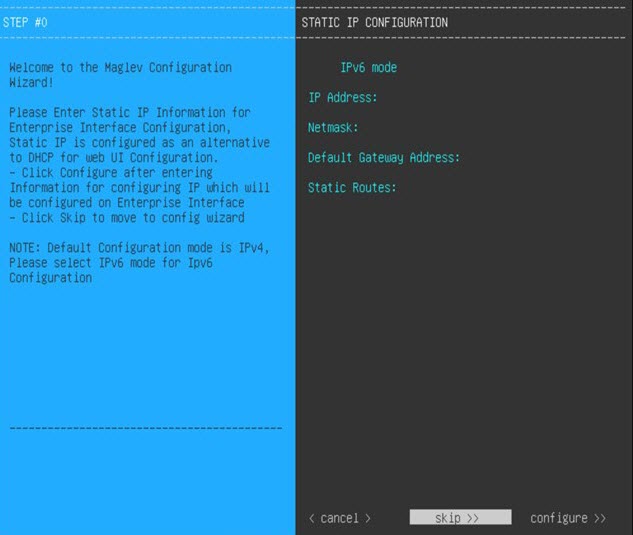
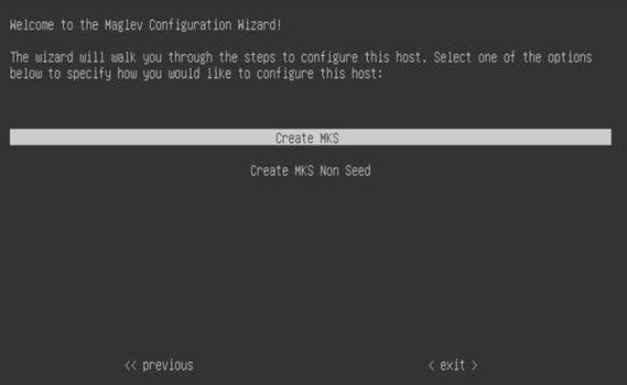
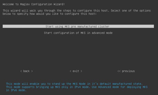
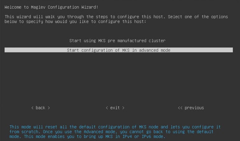
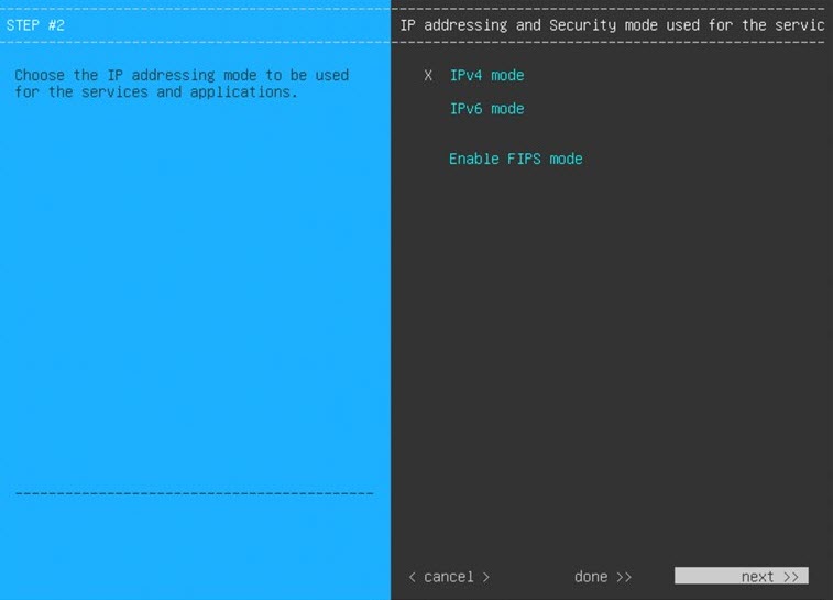
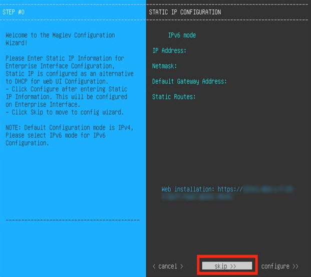
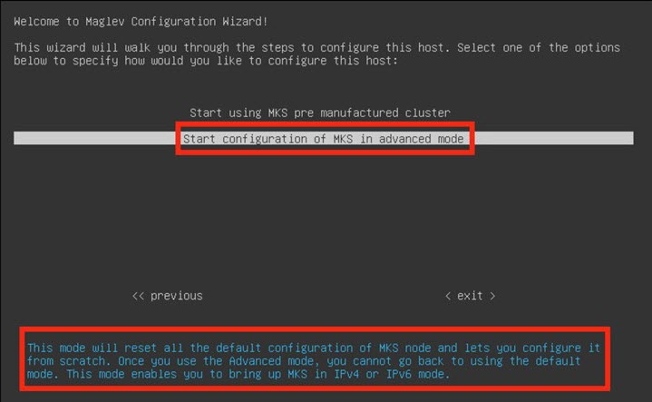
Configure a Virtual Appliance Using the Maglev Configuration Wizard: Default Mode
If you want to configure a virtual appliance as quickly as possible using the Maglev Configuration wizard and are okay with using preset appliance settings, complete the following procedure.
Note |
The Intracluster interface is preconfigured when using this wizard. If you don't want to use the default settings for this interface, you'll need to complete the Maglev Configuration wizard with advanced mode selected. |
Before you begin
Gather the following information for the virtual appliance before you start this procedure:
-
Static IP address
-
Subnet mask
-
Default gateway
-
DNS address
-
NTP server details
-
Proxy server details
Important |
If you plan to configure the appliance's Management interface, also configure an additional network adapter for this interface to reside on before you start this wizard. |
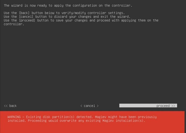
Procedure
|
Step 1 |
After deployment completes, power on the newly-created virtual machine:
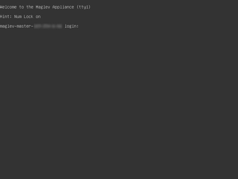
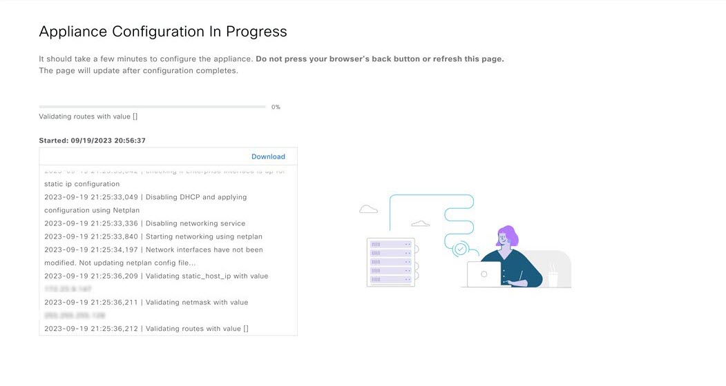
It takes around 45 minutes for the virtual machine to become operational. The actual time will depend on things like available bandwidth, RAM, hard disk space, and the number of vCPUs. You can monitor the progress in the VMware VM Console. |
||||||||||||||||||||||||||||||||||||||||||||||||
|
Step 2 |
Launch either the remote console or web console by clicking the appropriate link. 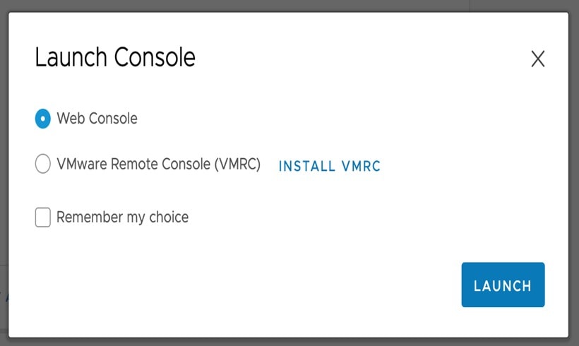 |
||||||||||||||||||||||||||||||||||||||||||||||||
|
Step 3 |
Configure the virtual machine by completing the Maglev Configuration Wizard:
|
||||||||||||||||||||||||||||||||||||||||||||||||
|
Step 4 |

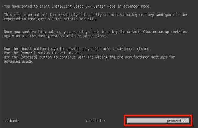
Configure a Virtual Appliance Using the Maglev Configuration Wizard: Advanced Mode for IPv4 Deployments
If you want to configure a virtual appliance using the Maglev Configuration wizard and need to specify settings that are different from the preset appliance settings, complete the following procedure.
Before you begin
Gather the following information for the virtual appliance before you start this procedure:
-
Static IP address
-
Subnet mask
-
Default gateway
-
DNS address
-
NTP server details
-
Proxy server details
Important |
If you plan to configure the appliance's Management interface, also configure an additional network adapter for this interface to reside on before you start this wizard. |
Procedure
|
Step 1 |
After deployment completes, power on the newly-created virtual machine:
|
||||||||||||||||||||||||||||||||||||||||||||||||||||||||||||
|
Step 2 |
Launch either the remote console or web console by clicking the appropriate link. |
||||||||||||||||||||||||||||||||||||||||||||||||||||||||||||
|
Step 3 |
Configure the virtual machine by completing the Maglev Configuration Wizard:
|
||||||||||||||||||||||||||||||||||||||||||||||||||||||||||||
|
Step 4 |
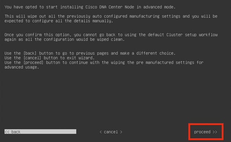
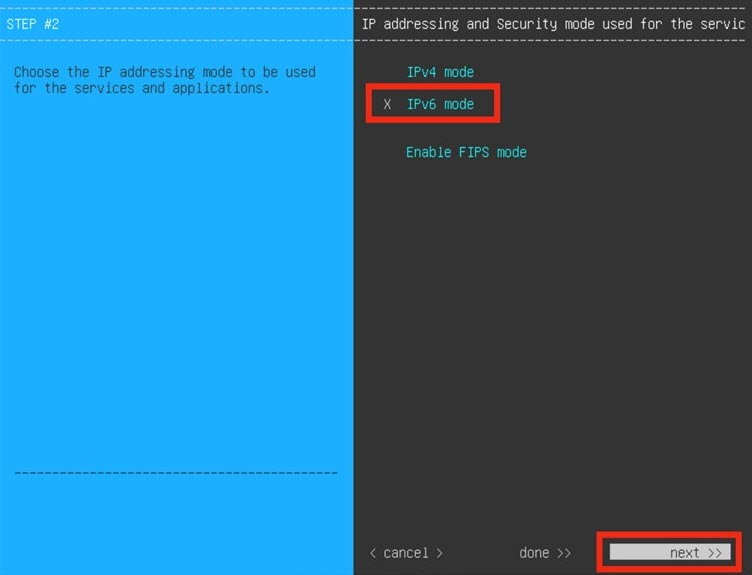
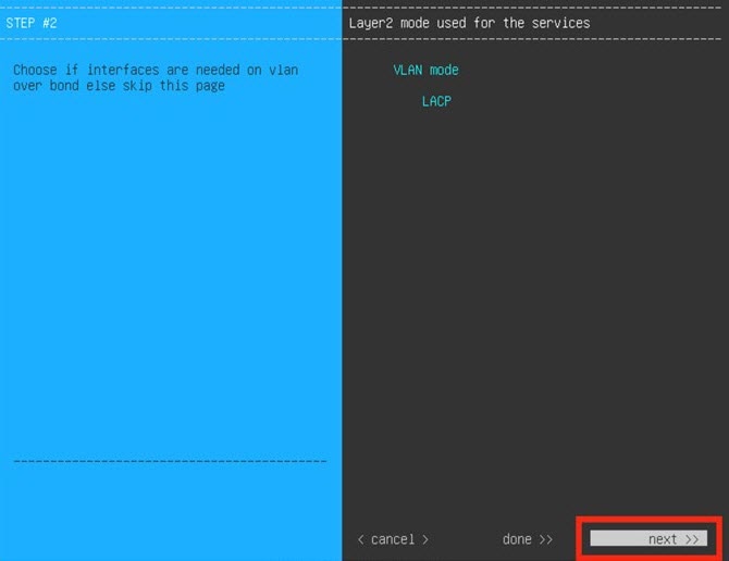
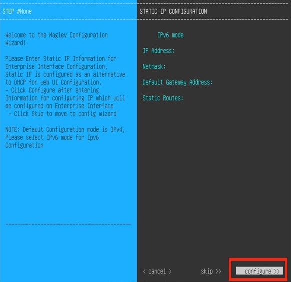
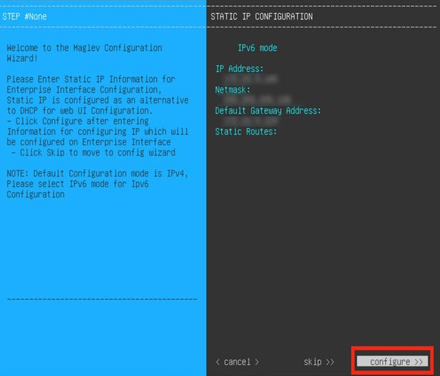
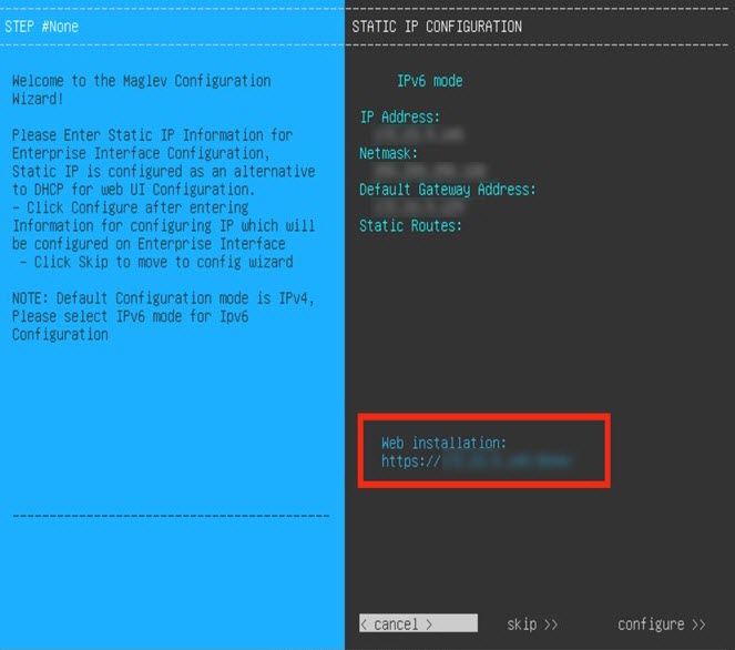
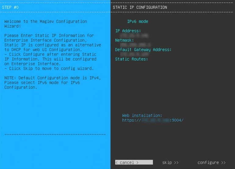
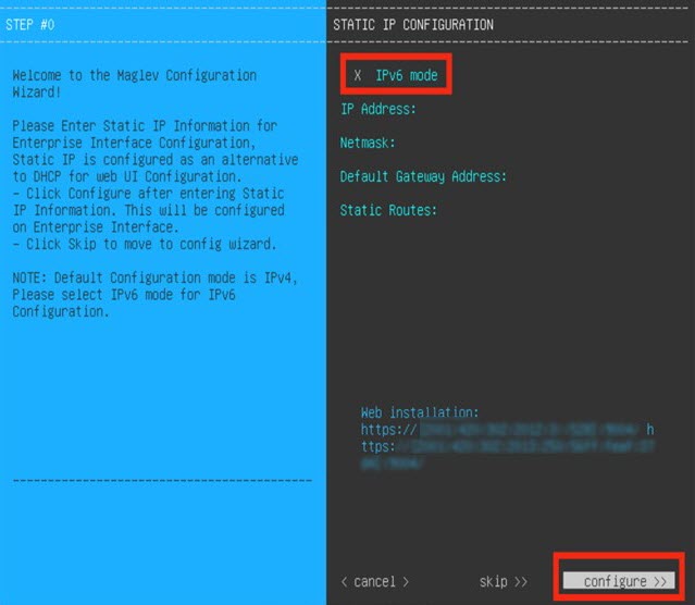
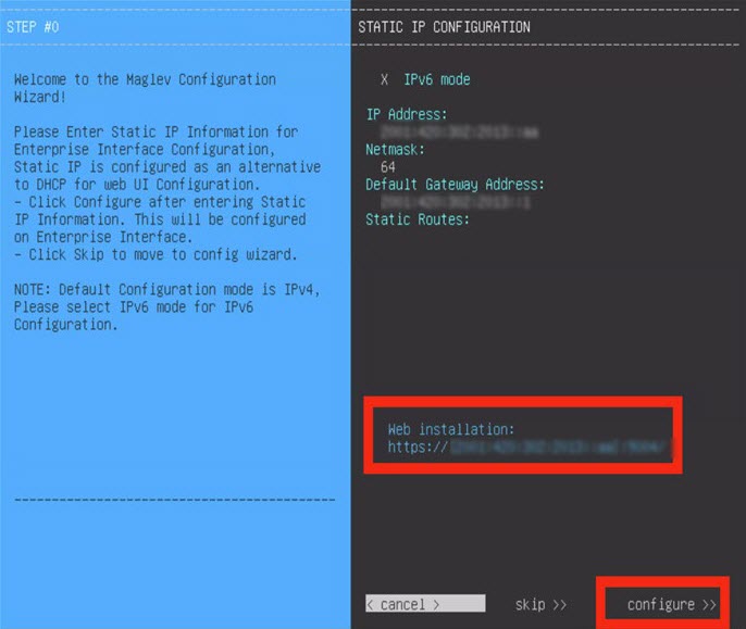
Configure a Virtual Appliance Using the Maglev Configuration Wizard: Advanced Mode for IPv6 Deployments
Gather the following information for the virtual appliance before you start this procedure:
-
Static IP address
-
Subnet mask
-
Default gateway
-
DNS address
-
NTP server details
-
Proxy server details
Important |
If you plan to configure the appliance's Management interface, also configure an additional network adapter for this interface to reside on before you start this wizard. |
If you want to configure a virtual appliance using the Maglev Configuration wizard and need to specify settings that are different from the preset appliance settings, complete the following procedure.
Procedure
|
Step 1 |
After deployment completes, power on the newly-created virtual machine:
|
||||||||||||||||||||||||||||||||||||||||||||||||||||||||||||||||||||
|
Step 2 |
Launch either the remote console or web console by clicking the appropriate link. |
||||||||||||||||||||||||||||||||||||||||||||||||||||||||||||||||||||
|
Step 3 |
Configure the virtual machine by completing the Maglev Configuration Wizard:
|
||||||||||||||||||||||||||||||||||||||||||||||||||||||||||||||||||||
|
Step 4 |

Configure a Virtual Appliance Using the Web UI Install Configuration Wizard
If you want to configure a virtual appliance as quickly as possible using the browser-based Install configuration wizard and are okay with using preset appliance settings, complete the following procedure.
Important |
Ensure that all of the IP addresses you enter while completing this procedure are valid IPv4 addresses with valid IPv4 netmasks. Also make sure that the addresses and their corresponding subnets do not overlap. Service communication issues can result if they do. |
Before you begin
Ensure that you collected the following information:
-
Static IP address
-
Subnet mask
-
Default gateway
-
DNS address
-
NTP server details
-
Proxy server details
Ensure that you are using a supported browser. See Deployment Requirements.
Ensure that you enabled ICMP on the firewall between Catalyst Center on ESXi and the DNS servers you will specify in the following procedure. This wizard uses Ping to verify the DNS server you specify. This ping can be blocked if there is a firewall between Catalyst Center on ESXi and the DNS server and ICMP is not enabled on that firewall. When this happens, you will not be able to complete the wizard.
Note |
The Intracluster interface is preconfigured when using this wizard. If you don't want to use the default settings for this interface, you'll need to complete the browser-based Advanced Install configuration wizard. |
Procedure
|
Step 1 |
After deployment completes, power on the newly-created virtual machine:
It takes around 45 minutes for the virtual machine to become operational. The actual time will depend on things like available bandwidth, RAM, hard disk space, and the number of vCPUs. You can monitor the progress in the vSphere Client's Recent Tasks tab. |
||||||||||||||||||||||||||||||||
|
Step 2 |
Launch either the remote console or web console by clicking the appropriate link. |
||||||||||||||||||||||||||||||||
|
Step 3 |
Open the Install Configuration wizard:
|
||||||||||||||||||||||||||||||||
|
Step 4 |
Configure your virtual appliance by completing the Install Configuration wizard:
|
||||||||||||||||||||||||||||||||
|
Step 5 |
After appliance configuration completes, click the copy icon to copy the default admin superuser password. 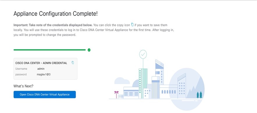
|
||||||||||||||||||||||||||||||||
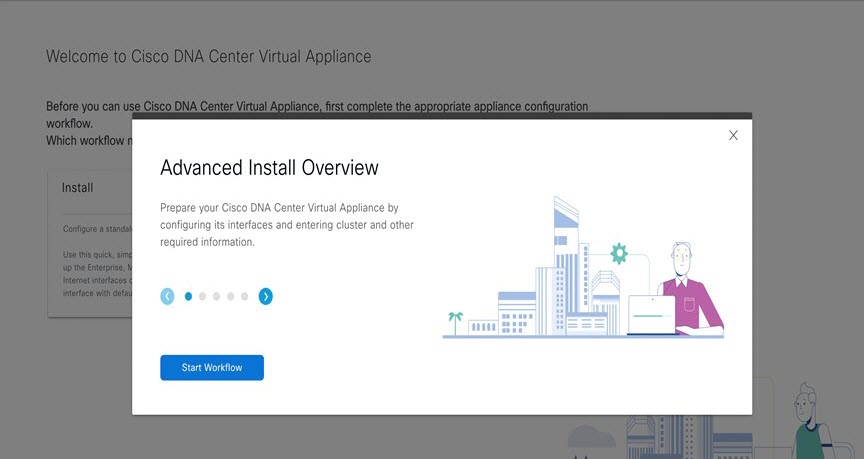
Configure a Virtual Appliance Using the Web UI Advanced Install Configuration Wizard for IPv4 Deployments
If you want to configure a virtual appliance using the browser-based Advanced Install configuration wizard and need to specify settings that are different from the preset appliance settings, complete the following procedure.
Important |
Ensure that all of the IP addresses you enter while completing this procedure are valid IPv4 addresses with valid IPv4 netmasks. Also make sure that the addresses and their corresponding subnets do not overlap. Service communication issues can result if they do. |
Before you begin
Ensure that you collected the following information:
-
Static IP address
-
Subnet mask
-
Default gateway
-
DNS address
-
NTP server details
-
Proxy server details
Ensure you are using a supported browser. See Deployment Requirements.
Ensure you enabled ICMP on the firewall between Catalyst Center on ESXi and both the default gateway and the DNS server you specify in the following procedure. The wizard uses ping to verify the gateway and DNS server you specify. This ping might get blocked if a firewall is in place and ICMP is not enabled on that firewall. When this happens, you will not be able to complete the wizard.
Procedure
|
Step 1 |
After deployment completes, power on the newly-created virtual machine:
It takes around 90 to 120 minutes for the virtual machine to become operational. The actual time will depend on things like available bandwidth, RAM, hard disk space, and the number of vCPUs. You can monitor the progress in the vSphere Client's Recent Tasks tab. |
||||||||||||||||||||||||||||||||||
|
Step 2 |
Launch either the remote console or web console by clicking the appropriate link. |
||||||||||||||||||||||||||||||||||
|
Step 3 |
Open the Advanced Install Configuration wizard:
|
||||||||||||||||||||||||||||||||||
|
Step 4 |
Configure your virtual appliance by completing the Advanced Install Configuration wizard:
|
||||||||||||||||||||||||||||||||||
|
Step 5 |
After appliance configuration completes, click the copy icon to copy the default admin superuser password. It can take from 15-30 mins for services to be stabilized before you can login to the UI.
|
||||||||||||||||||||||||||||||||||
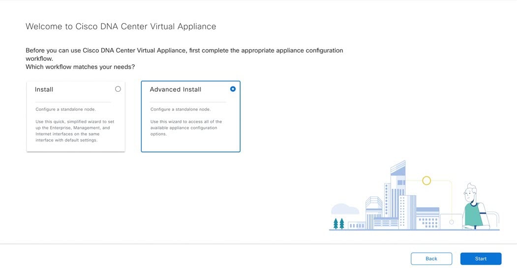
Configure a Virtual Appliance Using the Web UI Advanced Install Configuration Wizard for IPv6 Deployments
If you want to configure a virtual appliance using the browser-based Advanced Install configuration wizard and need to specify settings that are different from the preset appliance settings, complete the following procedure.
Important |
Ensure that all of the IP addresses you enter while completing this procedure are valid IPv4 addresses with valid IPv4 netmasks. Also make sure that the addresses and their corresponding subnets do not overlap. Service communication issues can result if they do. |
Before you begin
Ensure that you collected the following information:
-
Static IP address
-
Subnet mask
-
Default gateway
-
DNS address
-
NTP server details
-
Proxy server details
Ensure that you are using a supported browser. See Deployment Requirements.
Ensure that you enabled ICMP on the firewall between Catalyst Center on ESXi and both the default gateway and the DNS server you specify in the following procedure. The wizard uses ping to verify the gateway and DNS server you specify. This ping might get blocked if a firewall is in place and ICMP is not enabled on that firewall. When this happens, you will not be able to complete the wizard.
Procedure
|
Step 1 |
After deployment completes, power on the newly-created virtual machine:
It takes around 90 to 120 minutes for the virtual machine to become operational. The actual time will depend on things like available bandwidth, RAM, hard disk space, and the number of vCPUs. You can monitor the progress in the vSphere Client's Recent Tasks tab. |
||||||||||||||||||||||||||||||||||
|
Step 2 |
Launch either the remote console or web console by clicking the appropriate link. |
||||||||||||||||||||||||||||||||||
|
Step 3 |
Open the Advanced Install Configuration wizard:
|
||||||||||||||||||||||||||||||||||
|
Step 4 |
Configure your virtual appliance by completing the Advanced Install Configuration wizard:
|
||||||||||||||||||||||||||||||||||
|
Step 5 |
After appliance configuration completes, click the copy icon to copy the default admin superuser password. It can take from 15-30 mins for services to be stabilized before you can login to the UI.
|
||||||||||||||||||||||||||||||||||
Configure a Virtual Appliance Using the Interactive CC VA Launcher
To configure a Catalyst Center on ESXi virtual appliance using the CC VA Launcher, complete the following procedure.
Procedure
|
Step 1 |
From the location specified by Cisco, download the Catalyst Center on ESXi OVA file. |
|
Step 2 |
From the same URL, download the CC VA Launcher bundle (DNAC-SW-Launcher-2.3.7.4-VA.tar.gz) and extract it. The bundle contains the following files:
|
|
Step 3 |
Start the CC VA Launcher in interactive mode by entering the command that's specific to your operating system:
|
|
Step 4 |
Complete the CC VA Launcher: |
|
Step 5 |
After the Catalyst Center on ESXi virtual appliance powers on, log in to the host/vCenter server you deployed and open the virtual appliance's VMWare console. A terminal shell opens after the virtual appliance boots up, which can take up to 60 minutes. |
|
Step 6 |
Log in, using the same Maglev password you entered in Step 4v. The default username is maglev. |
|
Step 7 |
When all of the Catalyst Center on ESXi services are up, open a supported browser and type in the IP address you entered for the Enterprise interface in Step 4k. If you configured the Management interface, enter the IP address you entered for it in Step 4m. |
|
Step 8 |
When prompted by the Catalyst Center on ESXi GUI, enter the default credentials (admin/maglev1@3) to log in. |
Configuration File Parameters
The following table describes the parameters you need to enter values for in the config.json file.
Note |
For optional parameters you are not using, enter an empty string (""). For example, if you don't want to specify an FQDN for
the virtual appliance, its entry would look like this: |
| Category | Configuration Parameter | Description | ||
|---|---|---|---|---|
|
Host/vCenter information (host_info) |
ip (ip)1 |
IP address or FQDN of the vCenter or standalone ESXi host that the OVA will be imported to.
|
||
|
SSL Port (ssl_port)1 |
Port that HTTPS is configured for on the vCenter or ESXi host. The default port is 443. |
|||
|
Import configuration (import_info) |
OVA file path (ova_path) 1 |
Directory where the Catalyst Center on ESXi OVA file was downloaded to.
|
||
|
VM Name (vm_name) 1 |
Name of the VM. |
|||
|
Datacenter (data_center) 2 |
Name of the datacenter the virtual appliance OVA file will be imported to. This parameter is not applicable to standalone ESXi host deployments. |
|||
|
Cluster Name (cluster) 3 |
Name of the cluster where the virtual machine will reside. |
|||
|
Resource Pool (resource_pool)3 |
Resource pool in which the imported VM should be placed. This parameter is not applicable to ESXi host deployments. |
|||
|
Host Name (host_name)2 |
The ESXi host (managed by vCenter) in which the VM should be placed. This parameter is not applicable to standalone ESXi host deployments. |
|||
|
Datastore (datastore)1 |
Name of the datastore where the VMDK and other supporting files should be placed. |
|||
|
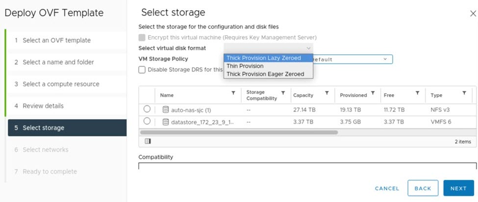
Disk Provision (disk_provision)1 |
The virtual disk's provisioning format. The thick provisioned format is set by default, but both thin and thick provisioning formats are supported. |
|||
|
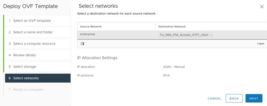
Enterprise Network (network: enterprise_network)1 |
Name of the host network that will be mapped to the virtual machine's Enterprise network. |
|||
|
Management Network (network: management_network)4 |
Name of the host network that will be mapped to the virtual machine's Management network, which is used to access Catalyst Center on ESXi's GUI.(Optional) |
|||
|
Catalyst Center on ESXi configuration information (dnac_info) |
IP Address (address)1 |
IP address of the virtual appliance's Enterprise network interface. |
||
|
Subnet mask (netmask) 1 |
Subnet mask for the virtual appliance's Enterprise network interface. |
|||
|
Gateway (gateway)1,5 |
IP address of the Enterprise network interface's gateway. |
|||
|
Routes (routes)5 |
Static routes for the Enterprise interface. Enter routes in the following format: <network-IP-address>/<netmask>/<gateway-IP-address>. If you're specifying multiple routes, separate them with a comma (,). |
|||
|
IP Address (address)4 |
IP address of the virtual appliance's Management interface. |
|||
|
Subnet mask (netmask) 4 |
Subnet mask for the virtual appliance's Management network interface. |
|||
|
Gateway (gateway)1,5 |
IP address of the Management network interface's gateway. |
|||
|
Routes (routes)5 |
Static routes for the Management interface. Enter routes in the following format: <network-IP-address>/<netmask>/<gateway-IP-address>. If you're specifying multiple routes, separate them with a comma (,). |
|||
|
DNS servers (dns_servers)1 |
DNS servers used by the virtual appliance. Specify at least one server. You can specify a maximum of three servers, separated by commas. |
|||
|
HTTP Proxy (http_proxy)6 |
HTTP proxy the virtual appliance will use. When specifying the proxy, use the following format: http://IP-address-or-FQDN:port-number
|
|||
|
NTP server (ntp)1 |
NTP servers used by the virtual appliance. Specify at least one server. You can specify a maximum of three servers, separated by commas. |
|||
|
FQDN (fqdn)6 |
Fully qualified domain name to be configured for the virtual appliance. Aside from hyphens, this name should not contain any special characters. |
Configure a Virtual Appliance Using the CC VA Launcher in Silent Mode
The CC VA Launcher's Silent mode allows you to deploy a Catalyst Center on ESXi virtual appliance using the settings specified in the config.json configuration file. This mode is useful when you want to integrate the launcher in your deployment automation workflow. To configure a virtual appliance using the launcher's silent mode, complete the following procedure.
Procedure
|
Step 1 |
From the location specified by Cisco, download the Catalyst Center on ESXi OVA file. |
||
|
Step 2 |
From the same URL, download the launcher bundle (DNAC-SW-Launcher-2.3.7.4-VA.tar.gz) and extract it. The bundle contains the following files:
|
||
|
Step 3 |
Navigate to the directory where the CC VA Launcher bundle files were extracted and open the configuration file in a text editor.
|
||
|
Step 4 |
For the parameters provided in the configuration file, enter the values specific to your deployment. See Configuration File Parameters for more information.
|
||
|
Step 5 |
Run the CC VA Launcher using the values you specified in the configuration file:
The CC VA Launcher completes the following tasks after it starts:
The deployment time will vary, depending on the available network bandwidth and target datastore's throughput. |
||
|
Step 6 |
After the virtual appliance powers on, enter the host/vCenter server's credentials to open the appliance's VMware console. It can take up to an hour for the a terminal shell to open. |
||
|
Step 7 |
Log in, using maglev as the username and the password you specified in Step 5. |
||
|
Step 8 |
After all of the Catalyst Center on ESXi services come up, use a supported browser to open the IP address you specified for the Enterprise interface in the configuration file. |
||
|
Step 9 |
Log in, using admin as the username and maglev1@3 as the password. |
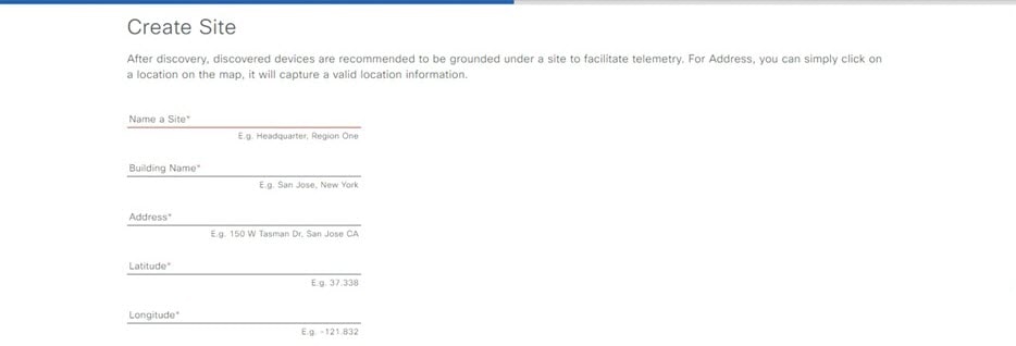
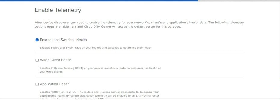
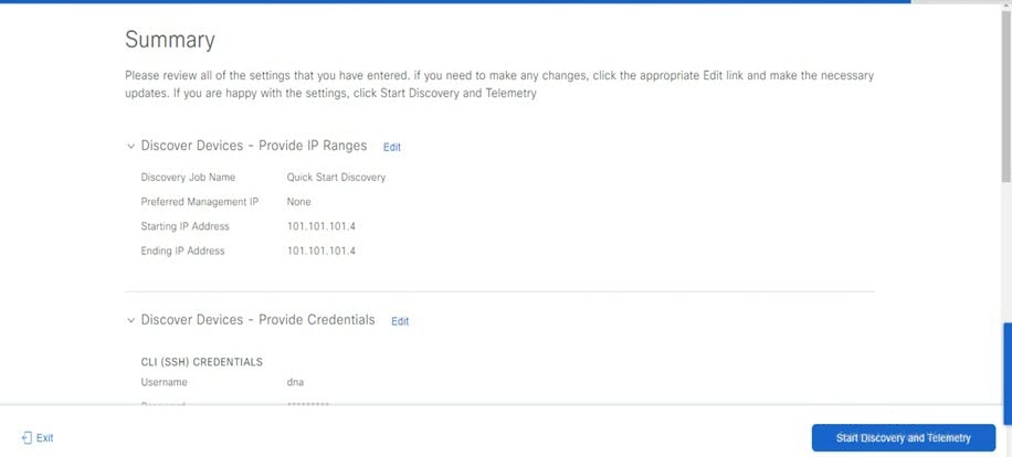
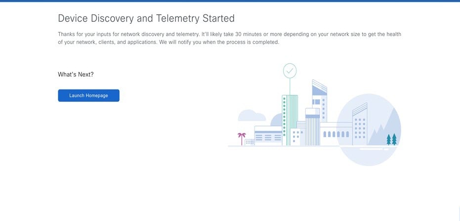
Complete the Quick Start Workflow
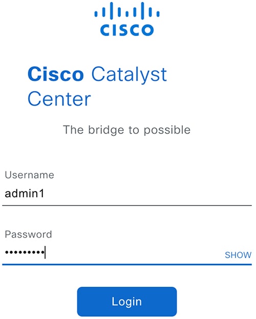
After you have deployed and configured a Catalyst Center on ESXi virtual appliance, you can log in to its GUI. Use a compatible, HTTPS-enabled browser when accessing Catalyst Center on ESXi.
When you log in for the first time as the admin superuser (with the username admin and the SUPER-ADMIN-ROLE assigned), the Quick Start workflow automatically starts. Complete this workflow to discover the devices that Catalyst Center on ESXi will manage and enable the collection of telemetry from those devices.
Before you begin
To log in to Catalyst Center on ESXi and complete the Quick Start workflow, you will need:
-
If you completed the Advanced Install configuration wizard, the admin superuser username and password that you specified.
-
The information described in the Cisco Catalyst Center Second-Generation Appliance Installation Guide's "Required First-Time Setup Information" topic.
Procedure
|
Step 1 |
Do one of the following:
One of the following messages appears (depending on the browser you are using):
|
||||||||||||||||||||||||||||||||||||||||||||||||
|
Step 2 |
Ignore the message and click Advanced. One of the following messages appears:
These messages appear because the controller uses a self-signed certificate. For information on how Catalyst Center on ESXi uses certificates, see the "Certificate and Private Key Support" section in the Cisco Catalyst Center Administrator Guide. |
||||||||||||||||||||||||||||||||||||||||||||||||
|
Step 3 |
Ignore the message and do one of the following:
 |
||||||||||||||||||||||||||||||||||||||||||||||||
|
Step 4 |
Click Log In. The Catalyst Center on ESXi login screen appears. |
||||||||||||||||||||||||||||||||||||||||||||||||
|
Step 5 |
Do one of the following and then click Login:
In the next screen, you are prompted to configure a new admin user (as the default credentials used to log in for the first time will be deleted). |
||||||||||||||||||||||||||||||||||||||||||||||||
|
Step 6 |
Do the following in the resulting dialog box, then click Submit.
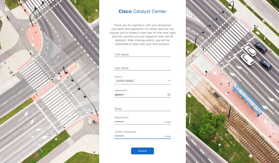 |
||||||||||||||||||||||||||||||||||||||||||||||||
|
Step 7 |
Click Log In. The Catalyst Center on ESXi login screen appears. |
||||||||||||||||||||||||||||||||||||||||||||||||
|
Step 8 |
Enter the username and password you configured for the new admin user, then click Login. 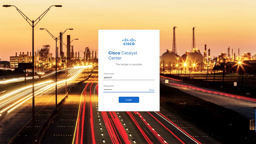 |
||||||||||||||||||||||||||||||||||||||||||||||||
|
Step 9 |
Enter your cisco.com username and password (which are used to register software downloads and receive system communications) and then click Next.
The Terms & Conditions screen opens, providing links to the software End User License Agreement (EULA) and any supplemental terms that are currently available. |
||||||||||||||||||||||||||||||||||||||||||||||||
|
Step 10 |
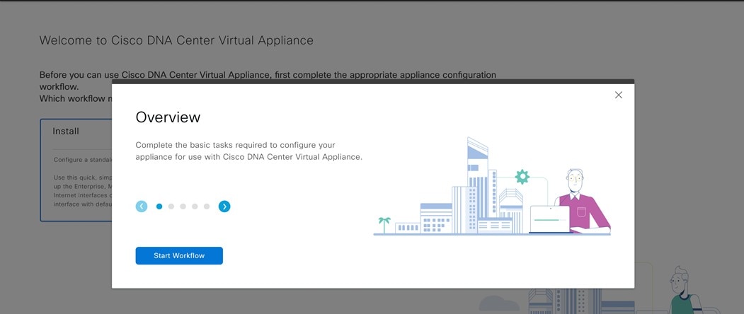
After reviewing these documents, click Next to accept the EULA. The Quick Start Overview slider opens. Click > to view a description of the tasks that the Quick Start workflow will help you complete in order to start using Catalyst Center on ESXi. 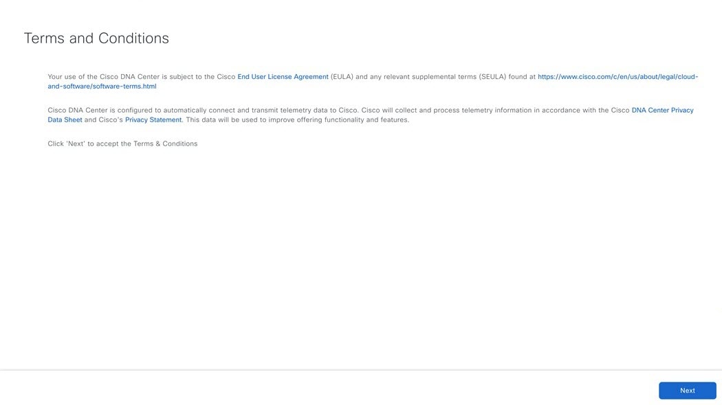 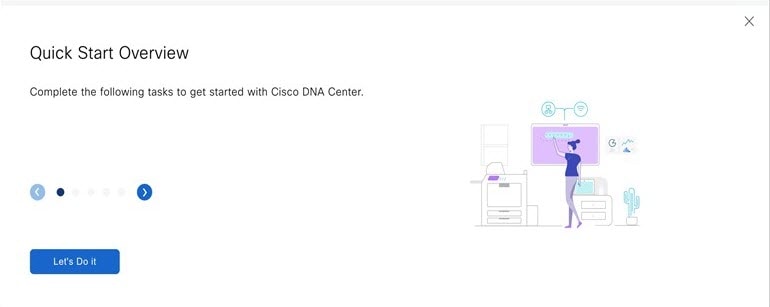 |
||||||||||||||||||||||||||||||||||||||||||||||||
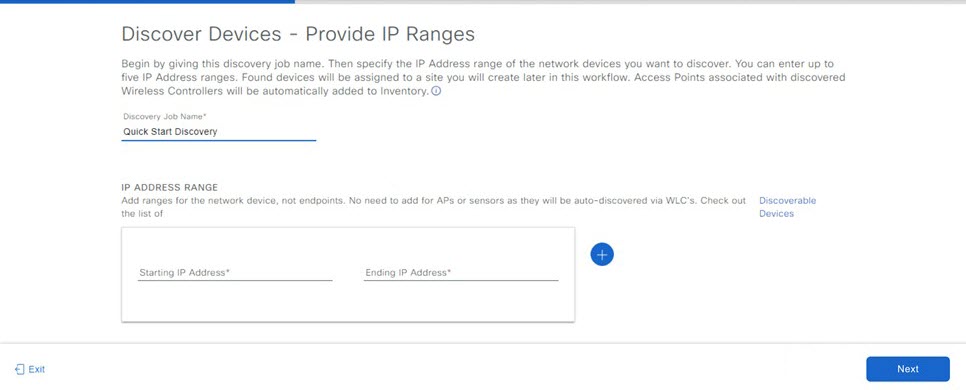
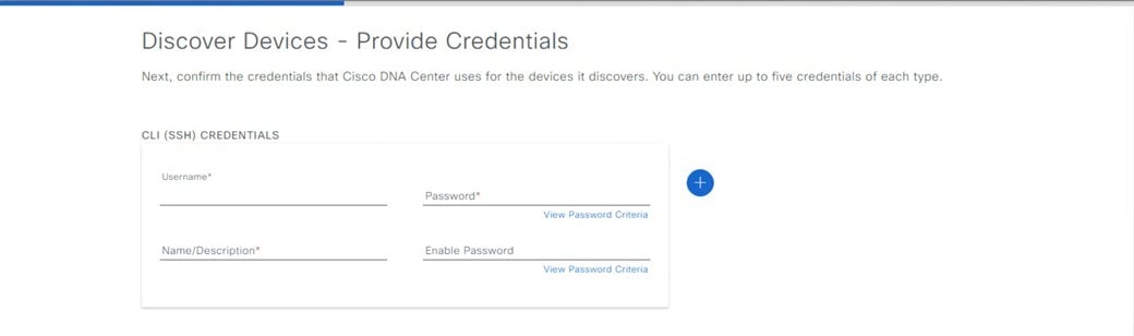
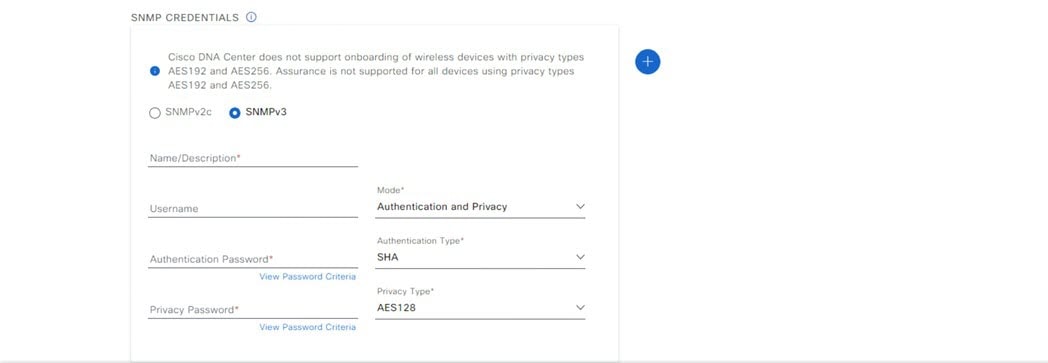
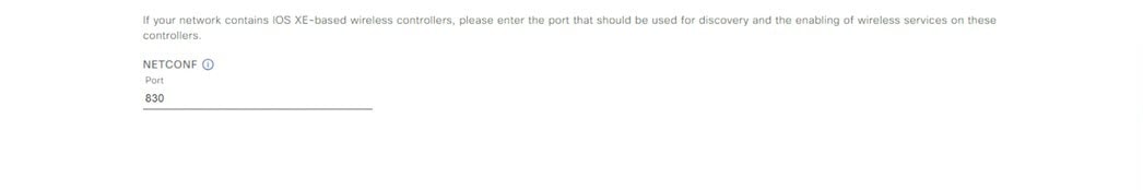
|
Step 11 |
Complete the Quick Start workflow:
|
||||||||||||||||||||||||||||||||||||||||||||||||
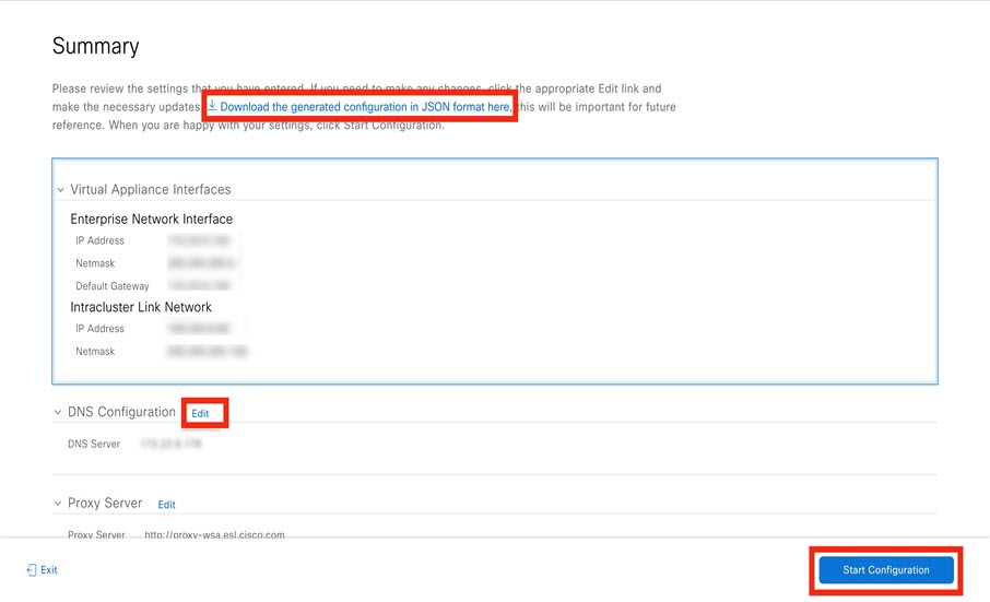
Postdeployment Configurations
After deploying a virtual appliance, you'll need to complete the following postdeployment tasks to run the appliance.
Enable VM Restart Priority
If VMware vSphere HA is enabled in your environment, complete the following procedure to ensure that the virtual appliance's VM is prioritized to power on first during an HA failover.
Procedure
|
Step 1 |
In the vSphere Client's navigation pane, click the HA cluster. |
|
Step 2 |
Click the Configure tab. |
|
Step 3 |
Choose and then click Add. |
|
Step 4 |
Click the virtual machine you want to apply overrides to and then click OK. |
|
Step 5 |
In the vSphere HA area's VM Restart Priority field, do the following:
|
|
Step 6 |
Click Finish. |
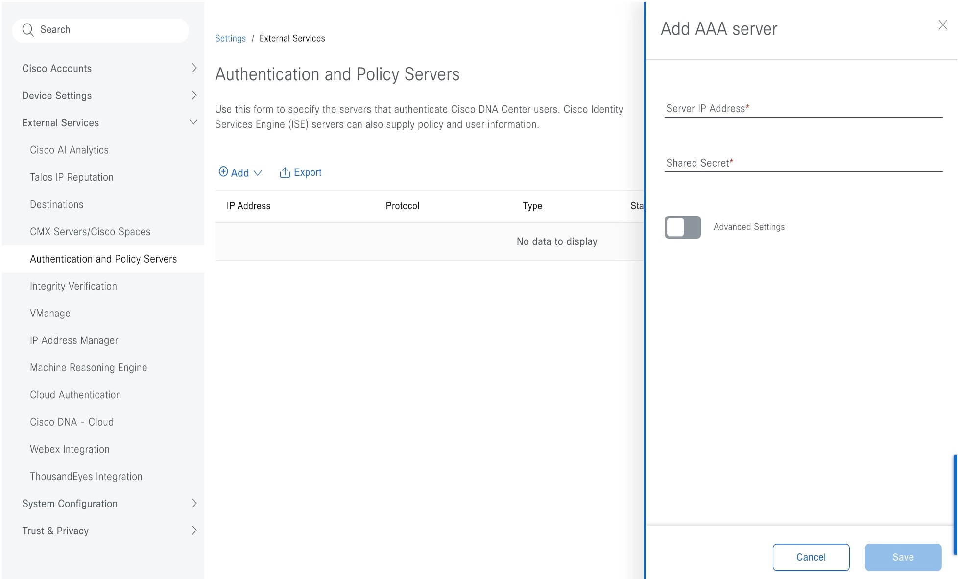
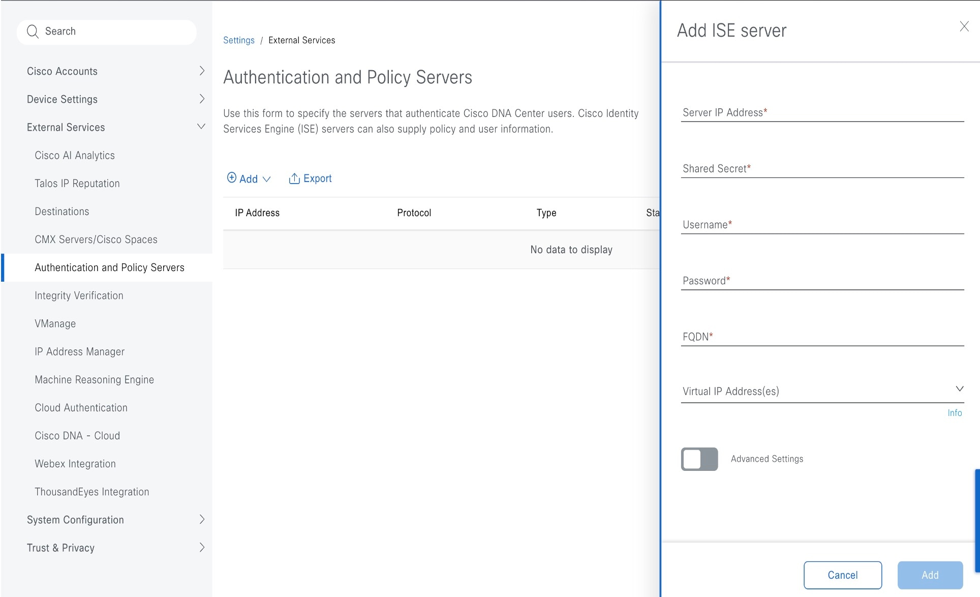
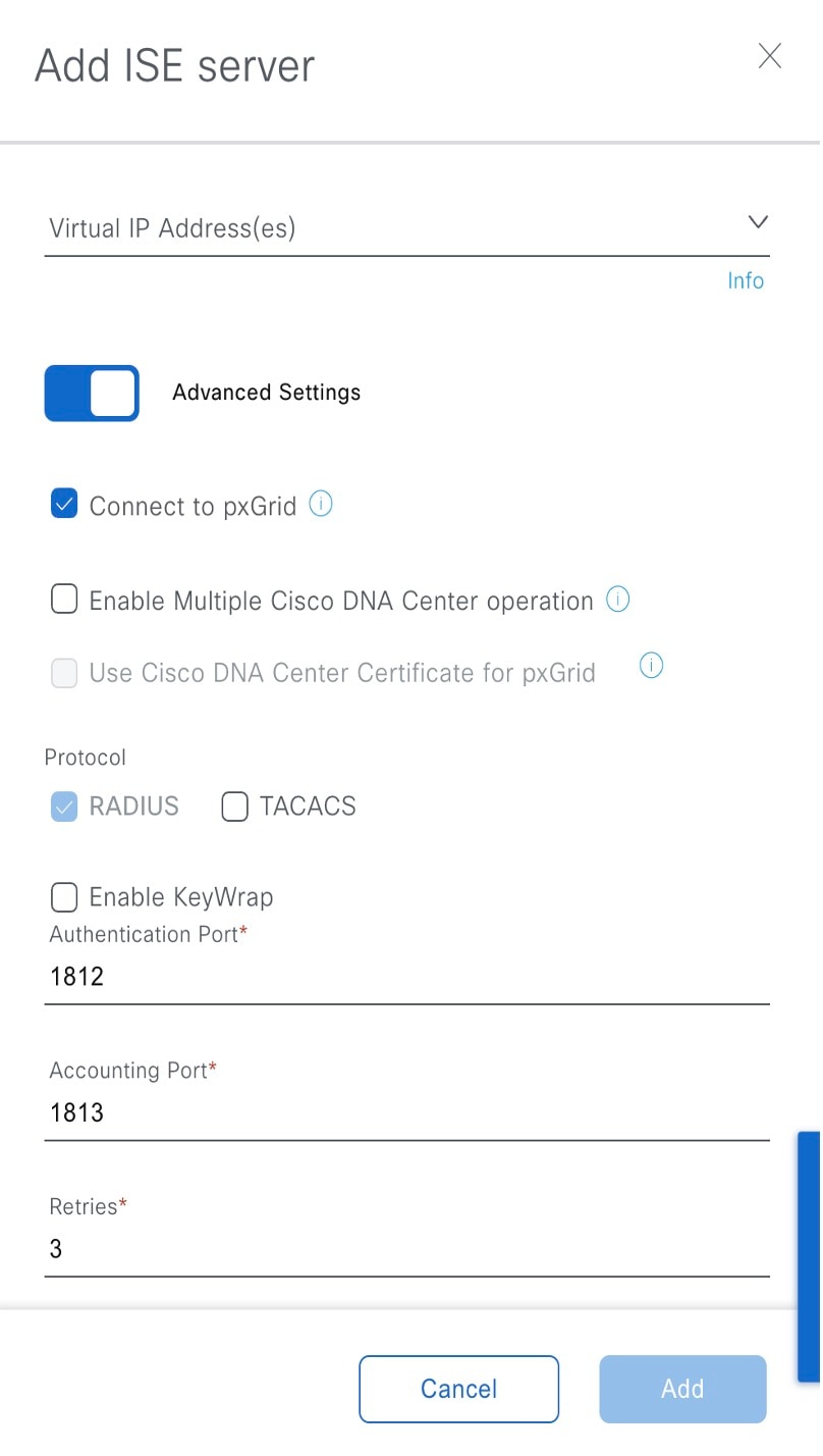
Configure Authentication and Policy Servers
Catalyst Center uses AAA servers for user authentication and Cisco ISE for both user authentication and access control. Use this procedure to configure AAA servers, including Cisco ISE.
Before you begin
If you are using Cisco ISE to perform both policy and AAA functions, make sure that Catalyst Center and Cisco ISE are integrated.
If you are using another product (not Cisco ISE) to perform AAA functions, make sure to do the following:
-
Register Catalyst Center with the AAA server, including defining the shared secret on both the AAA server and Catalyst Center.
-
Define an attribute name for Catalyst Center on the AAA server.
-
For a Catalyst Center multihost cluster configuration, define all individual host IP addresses and the virtual IP address for the multihost cluster on the AAA server.
Before you configure Cisco ISE, confirm that:
-
You have deployed Cisco ISE on your network. For information on supported Cisco ISE versions, see the Cisco Catalyst Center Compatibility Matrix. For information on installing Cisco ISE, see the Cisco Identity Services Engine Install and Upgrade guides.
-
If you have a standalone Cisco ISE deployment, you must integrate Catalyst Center with the Cisco ISE node and enable the pxGrid service and External RESTful Services (ERS) on that node.
Note
Although pxGrid 2.0 allows up to four pxGrid nodes in the Cisco ISE deployment, Catalyst Center releases earlier than 2.2.1.x do not support more than two pxGrid nodes.
-
If you have a distributed Cisco ISE deployment:
You must integrate Catalyst Center with the primary policy administration node (PAN), and enable ERS on the PAN.
Note
We recommend that you use ERS through the PAN. However, for backup, you can enable ERS on the Policy Service Nodes (PSNs).
You must enable the pxGrid service on one of the Cisco ISE nodes within the distributed deployment. Although you can choose to do so, you do not have to enable pxGrid on the PAN. You can enable pxGrid on any Cisco ISE node in your distributed deployment.
The PSNs that you configure in Cisco ISE to handle TrustSec or SD Access content and Protected Access Credentials (PACs) must also be defined in . For more information, see the Cisco Identity Services Engine Administrator Guide.
-
You must enable communication between Catalyst Center and Cisco ISE on the following ports: 443, 5222, 8910, and 9060.
-
The Cisco ISE host on which pxGrid is enabled must be reachable from Catalyst Center on the IP address of the Cisco ISE eth0 interface.
-
The Cisco ISE node can reach the fabric underlay network via the appliance's NIC.
-
The Cisco ISE admin node certificate must contain the Cisco ISE IP address or the fully qualified domain name (FQDN) in either the certificate subject name or the Subject Alternative Name (SAN).
-
The Catalyst Center system certificate must list both the Catalyst Center appliance IP address and FQDN in the SAN field.
Note
For Cisco ISE 2.4 Patch 13, 2.6 Patch 7, and 2.7 Patch 3, if you are using the Cisco ISE default self-signed certificate as the pxGrid certificate, Cisco ISE might reject that certificate after applying those patches. This is because the older versions of that certificate have the Netscape Cert Type extension specified as the SSL server, which now fails (because a client certificate is required).
This issue doesn’t occur in Cisco ISE 3.0 and later. For more information, see the Cisco ISE Release Notes.
Procedure
|
Step 1 |
From the top-left corner, click the menu icon and choose . 
|
||||
|
Step 2 |
From the Add drop-down list, choose AAA or ISE. 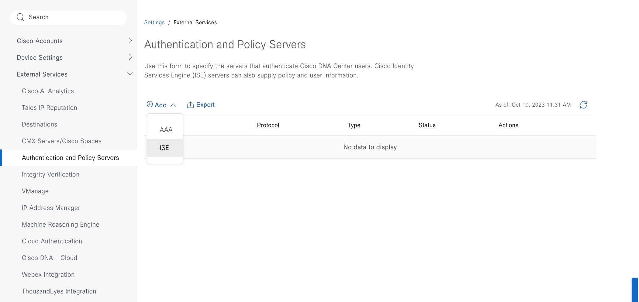
|
||||
|
Step 3 |
To configure the primary AAA server, enter the following information:
|
||||
|
Step 4 |
To configure a Cisco ISE server, enter the following details:
|
||||
|
Step 5 |
Click Advanced Settings and configure the settings:
|
||||
|
Step 6 |
Click Add. |
||||
|
Step 7 |
To add a secondary server, repeat the preceding steps. |
||||
|
Step 8 |
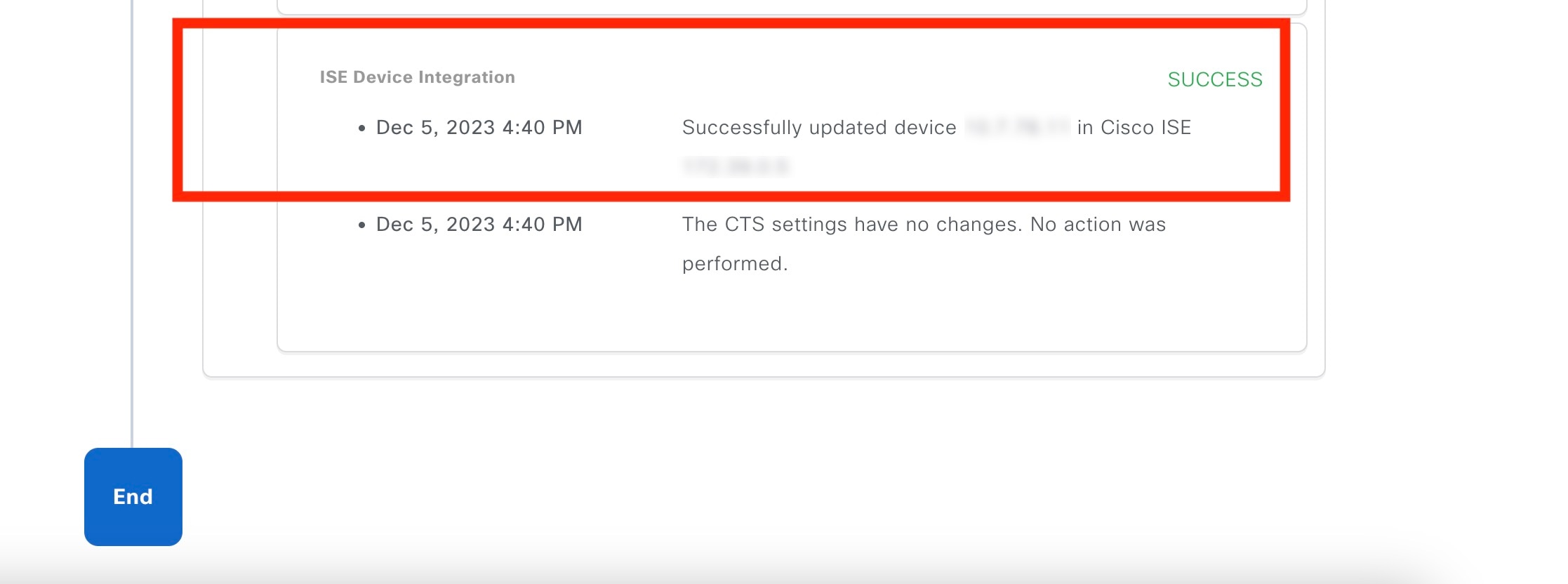
To view the Cisco ISE integration status of a device, do the following:
|
High Availability
VMware vSphere High Availability (HA) provides high availability for Catalyst Center on ESXi by linking the virtual machines and their hosts in the same vSphere cluster. vSphere HA requires shared storage to function. If a host failure occurs, the virtual machines restart on alternate hosts. vSphere HA responds to the failure based on its configuration, and vSphere HA detects the failure at the following levels:
-
Host level
-
Virtual machine (VM) level
-
Application level
In the current release, Catalyst Center only supports high availability for host-level failures.
Configure VMware vSphere HA for Host-Level Failures
To configure vSphere HA for host-level failures, complete the following procedure.
Before you begin
For the Catalyst Center virtual machine to take over from the failed hosts, at least two hosts must have the unreserved CPU/Memory resources described in the Cisco Catalyst Center on ESXi Release Notes.
Note |
Enable HA Admission Control with the appropriate configuration to ensure that the Catalyst Center virtual machine has sufficient resources to take over for the failed host. The configuration should allow the virtual machine to be restarted on another host without any impact to the system. If the necessary resources are not reserved, the virtual machine restarted on the failover host may fail due to resource shortage. |
Procedure
|
Step 1 |
Log in to the vSphere Client. |
|
Step 2 |
Choose the appropriate Catalyst Center cluster in the device menu. |
|
Step 3 |
To configure the cluster, choose . |
|
Step 4 |
From the top-right corner, click Edit. |
|
Step 5 |
Click the toggle button to enable vSphere HA. |
|
Step 6 |
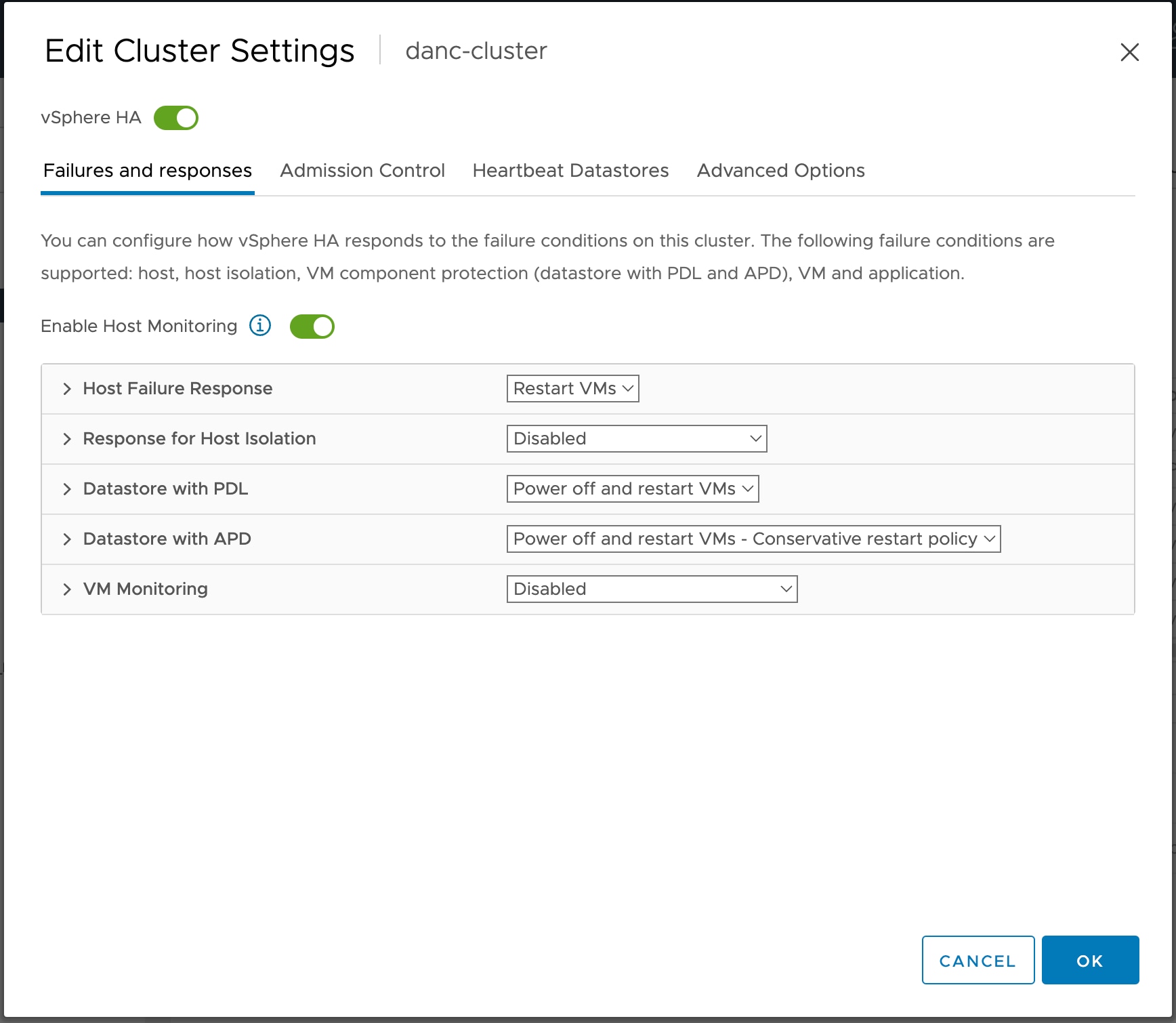
Choose Failures and responses and configure the following settings:
|
|
Step 7 |
Click OK. |
Configure Catalyst Center on ESXi Virtual Machine for Priority Restart
For the Catalyst Center on ESXi virtual machine to have priority restart upon host failure, complete the following procedure.
Procedure
|
Step 1 |
Log in to the vSphere Client. |
|
Step 2 |
Choose the appropriate Catalyst Center on ESXi cluster in the device menu. |
|
Step 3 |
To configure the cluster, choose . |
|
Step 4 |
In the Select a VM window, choose the deployed Catalyst Center on ESXi virtual machine. |
|
Step 5 |
Click OK. |
|
Step 6 |
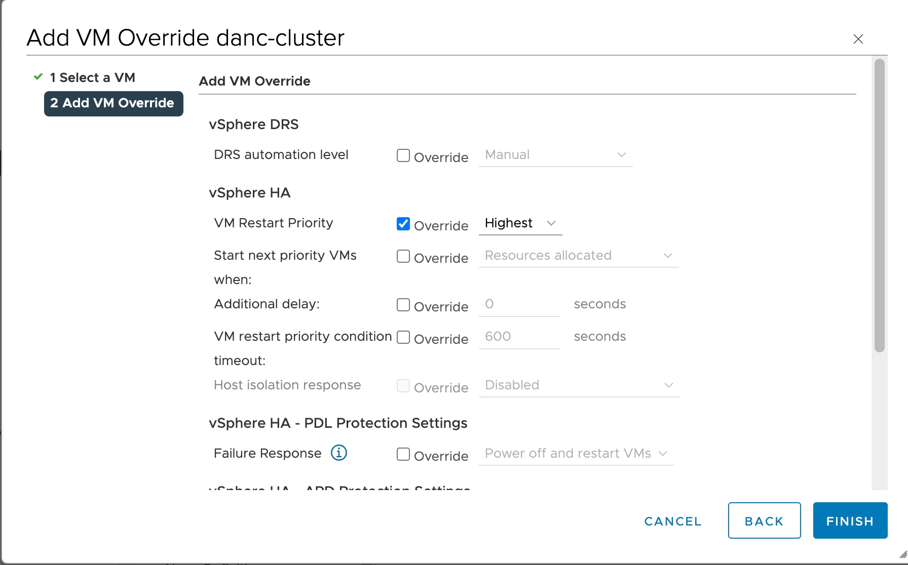
In the Add VM Override window, go to and configure the following settings:
|
|
Step 7 |
Click FINISH. |
VMware vSphere Product Documentation
Catalyst Center on ESXi supports high availability through VMware vSphere HA functionality. For information about VMware vSphere's implementation and requirements for creating and using a vSphere HA cluster, see the following VMware vSphere Product Documentation:
Backup and Restore
You can use the backup and restore functions to create the backup files and to restore to the same or different virtual appliance (if required for your network configuration).
Automation and Assurance data are unified to use a single data storage device. The data can be stored on a physical disk that is attached to the virtual machine or on a remote Network File System (NFS) server.
Backup
You can back up both automation and Assurance data.
Automation data consists of Catalyst Center databases, credentials, file systems, and files. The automation backup is always a full backup.
Assurance data consists of network assurance and analytics data. The first backup of Assurance data is a full backup. After that, backups are incremental.
Note |
Do not modify the backup files. If you do, you might not be able to restore the backup files to Catalyst Center on ESXi. |
Catalyst Center on ESXi creates the backup files and posts them to a physical disk or an NFS server.
You can add multiple physical disks for backup. If the previous backup disk runs out of disk space, you can use the other added disks for backup. For information on how to add a physical disk, see Add a Physical Disk for Backup and Restore. You must change the disk in the window, and save changes for the new disk to be used as a backup location. For information on how to change the physical disk, see Configure the Location to Store Backup Files.
You can also add multiple NFS servers for backup. For information on how to add an NFS server, see Add the NFS Server. You must change the NFS server in the window, and save changes for the new NFS server to be used as a backup location. For information on how to change the NFS server, see Configure the Location to Store Backup Files.
Note |
Only a single backup can be performed at a time. Performing multiple backups at once is not supported. |
When a backup is being performed, you cannot delete the files that have been uploaded to the backup server, and changes that you make to these files might not be captured by the backup process.
We recommend the following:
-
Perform a daily backup to maintain a current version of your database and files.
-
Perform a backup after making changes to your configuration, for example, when changing or creating a new policy on a device.
-
Perform a backup only during a low-impact or maintenance period.
You can schedule weekly backups on a specific day of the week and time.
Restore
You can restore backup files from the physical disk or NFS server using Catalyst Center on ESXi.
Catalyst Center on ESXi supports cross-version backup and restore; that is, you can create a backup on one version of Catalyst Center on ESXi and restore it to another version of Catalyst Center on ESXi. For example, a backup on Catalyst Center on ESXi 2.3.7.0-75530 version can be restored to Catalyst Center on ESXi 2.3.7.3-75176 version. The same applies to the later releases of Catalyst Center on ESXi.
Note |
A backup created on a virtual machine can only be restored on a virtual machine with the same or later software version. |
When you restore the backup files, Catalyst Center on ESXi removes and replaces the existing database and files with the backup database and files. While a restore is being performed, Catalyst Center on ESXi is unavailable.
You can restore the backup files of a failed or faulty virtual appliance. For more information, see Restore Data from a Physical Disk for a Faulty Virtual Appliance and Restore Data from an NFS Server for a Faulty Virtual Appliance.
Also, you can restore a backup to a Catalyst Center on ESXi appliance with a different IP address.
Note |
After a backup and restore of Catalyst Center on ESXi, you must access the Integration Settings window and update (if necessary) the Callback URL Host Name or IP Address. |
Backup and Restore Event Notifications
You can receive a notification whenever a backup or restore event takes place. To configure and subscribe to these notifications, complete the steps described in the "Work with Event Notifications" topic of the Cisco Catalyst Center Platform User Guide. When completing this procedure, ensure that you select and subscribe to the SYSTEM-BACKUP and SYSTEM-RESTORE events.
| Operation | Event |
|---|---|
|
Backup |
The process to create a backup file for your system has started. |
|
A backup file could not be created for your system.
|
|
|
Restore |
The process to restore a backup file has started. |
|
The restoration of a backup file failed.
|
NFS Backup Server Requirements
To support data backups on the NFS server, the server must be a Linux-based NFS server that meets the following requirements:
-
Support NFS v4 and NFS v3. (To verify this support, from the server, enter nfsstat -s.)
-
Have read and write permissions on the NFS export directory.
-
Have a stable network connection between Catalyst Center on ESXi and the NFS server.
-
Have sufficient network speed between Catalyst Center on ESXi and the NFS server.
Note |
You cannot use an NFS-mounted directory as the backup server. A cascaded NFS mount adds a layer of latency and is therefore not supported. |
Requirements for Multiple Catalyst Center on ESXi Deployments
If your network includes multiple Catalyst Center clusters, the following example configuration shows how to name your NFS server backup directory structure:
| Resource | Example Configuration |
|---|---|
|
Catalyst Center on ESXi clusters |
|
|
Backup server hosting automation and Assurance backups |
The example directory is /data/, which has ample space to host both types of backups. |
|
NFS export configuration |
The content of the /etc/exports file: |
Backup Physical Disk Nomenclature
To use a physical disk for backup, you must add a physical disk to the virtual machine. To easily identify the physical disks for backups, UUID is used.
UUID is a unique identifier that is associated with the disk, which does not change across reboots. A disk that is removed and added to a different cluster will have the same UUID, as long as it is not formatted again.
The disk is explicitly labeled as mks-managed.
You can view the physical disks available for backup in the window, under the Mount Path drop-down list.
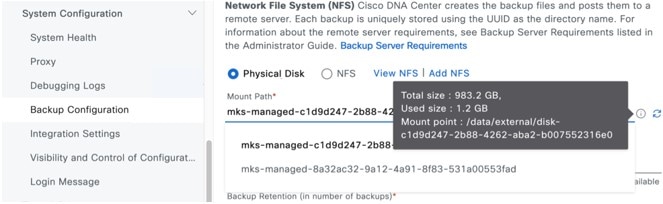
Hover over the i icon to view the physical disk nomenclature, which is shown in the following format:
/data/external/disk-<uuid>
Backup Storage Requirements
Catalyst Center on ESXi stores backup copies of Assurance and automation data on a physical disk that is attached to the virtual machine or a remote NFS server. You must allocate enough external storage for your backups to cover the required retention. We recommend the following storage.
| Virtual Appliance | Assurance Data Storage (14 Days Incremental) |
Automation Data Storage (Daily Full) |
Physical Disk/NFS Server (Assurance and Automation) Storage |
|---|---|---|---|
|
DN-SW-APL |
1.75 TB |
50 GB |
1.75 TB + 50 GB |
Additional notes:
-
The preceding table assumes fully loaded virtual appliance configurations that support the maximum number of access points and network devices for each appliance.
-
The automation backup sizing is estimated for one daily backup. If you want to retain backups for additional days, multiply the required storage by the additional number of days. For example, if you have a DN-SW-APL virtual appliance and you want to store five copies of automation data backups generated once each day, the total storage required is 5 * 50 GB = 250 GB.
-
The total backup time varies depending on your daily data load and the amount of historical data that you want to retain.
-
The write path to Catalyst Center depends on the network throughput from Catalyst Center to the NFS server. The NFS server must have a throughput of at least 100 MB/sec.
-
As with any other IT service, monitoring NFS performance is required to ensure optimal performance.
Add a Physical Disk for Backup and Restore
Use this procedure to add a physical disk that can be used for backup and restore operations.
Procedure
|
Step 1 |
If your appliance is running on the machine that's hosting Catalyst Center on ESXi, power off the appliance's virtual machine. 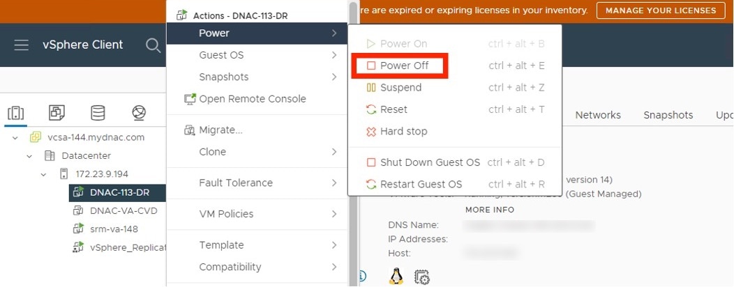
|
||
|
Step 2 |
Log in to VMware vSphere. |
||
|
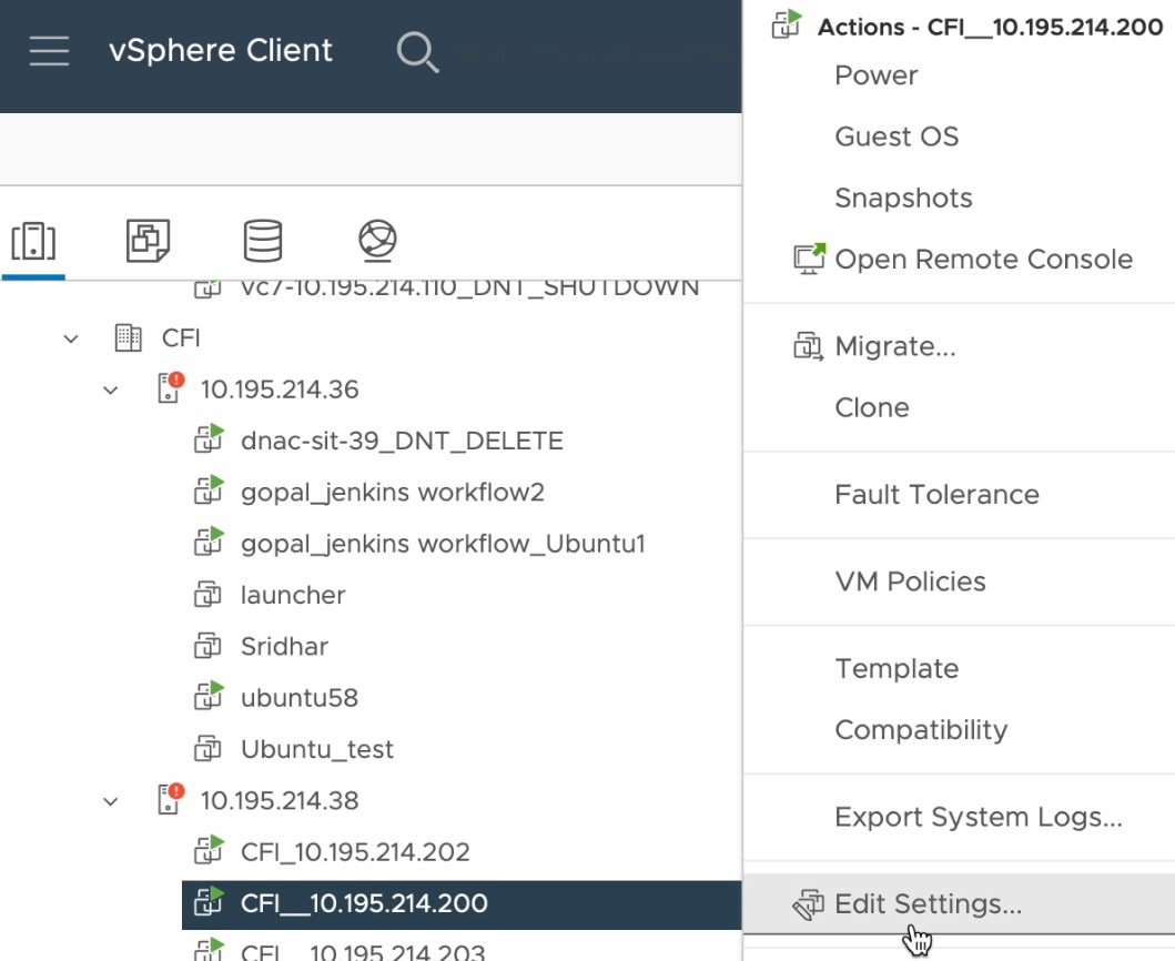
Step 3 |
From the vSphere client's left pane, right-click the ESXi host and then choose Edit Settings. 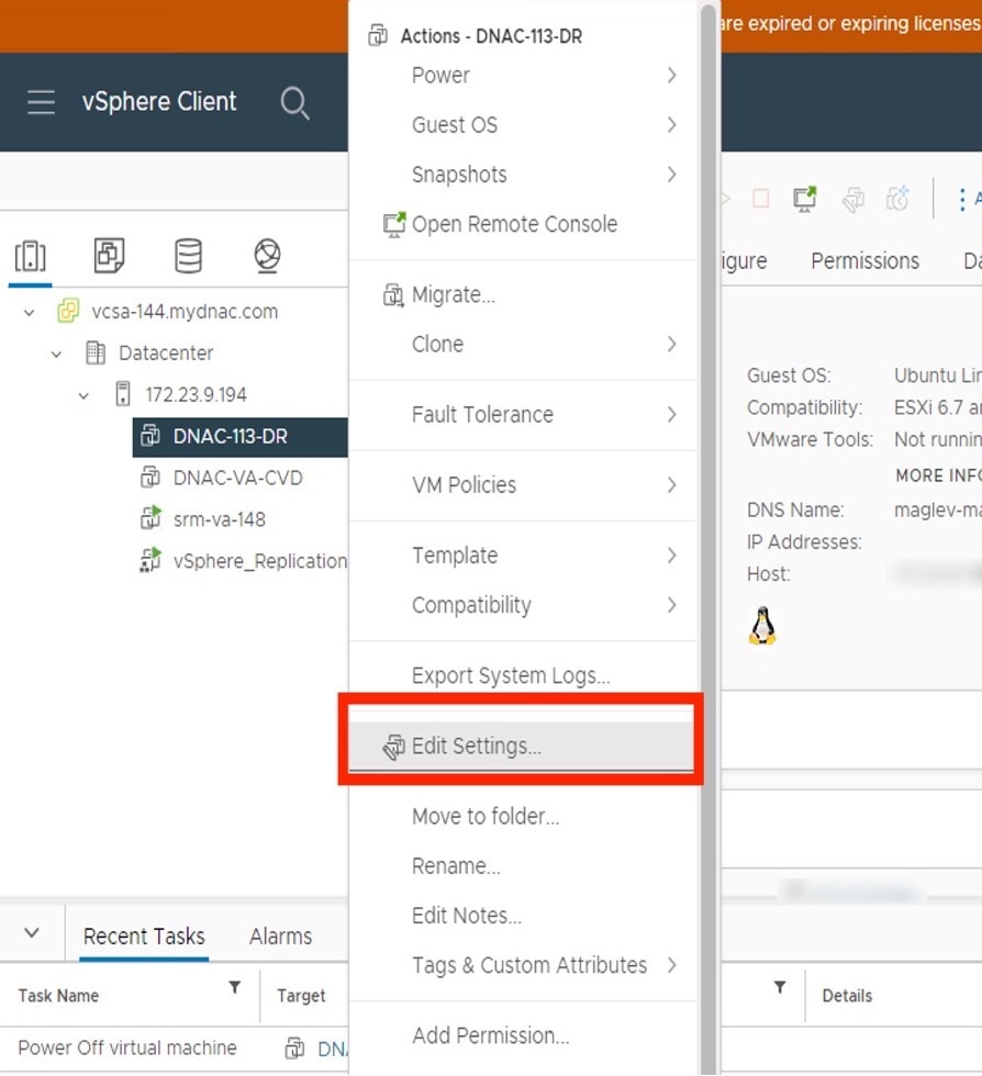
|
||
|
Step 4 |
In the Edit Settings dialog box, click Add New Device and then choose Hard Disk. 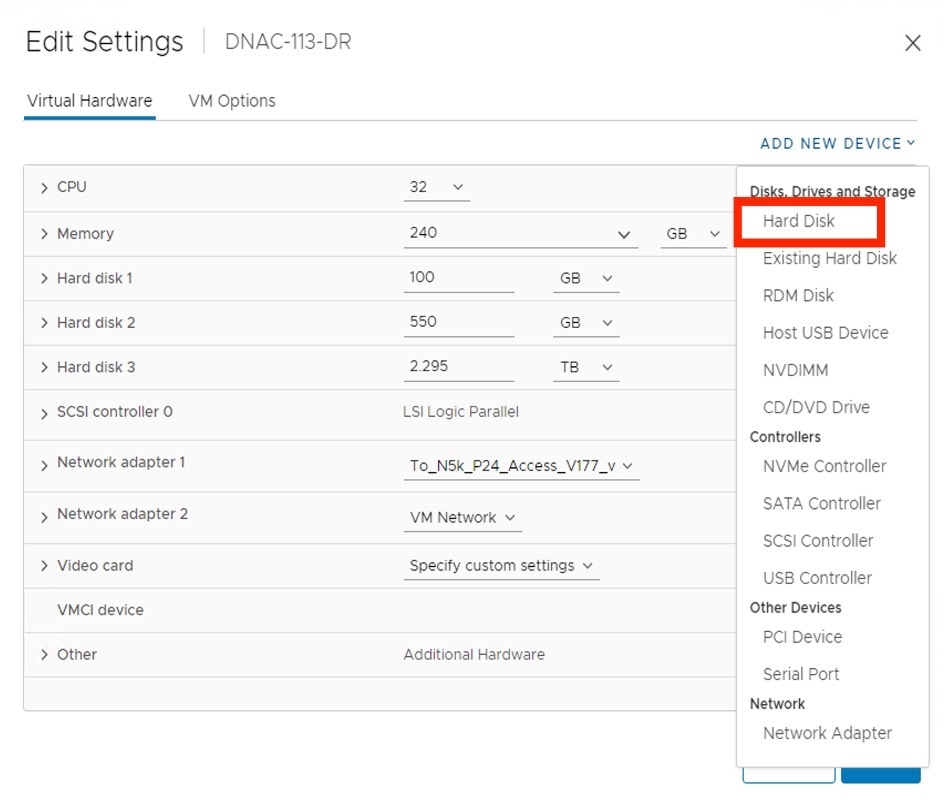
|
||
|
Step 5 |
In the New Hard disk field, enter the desired storage size. 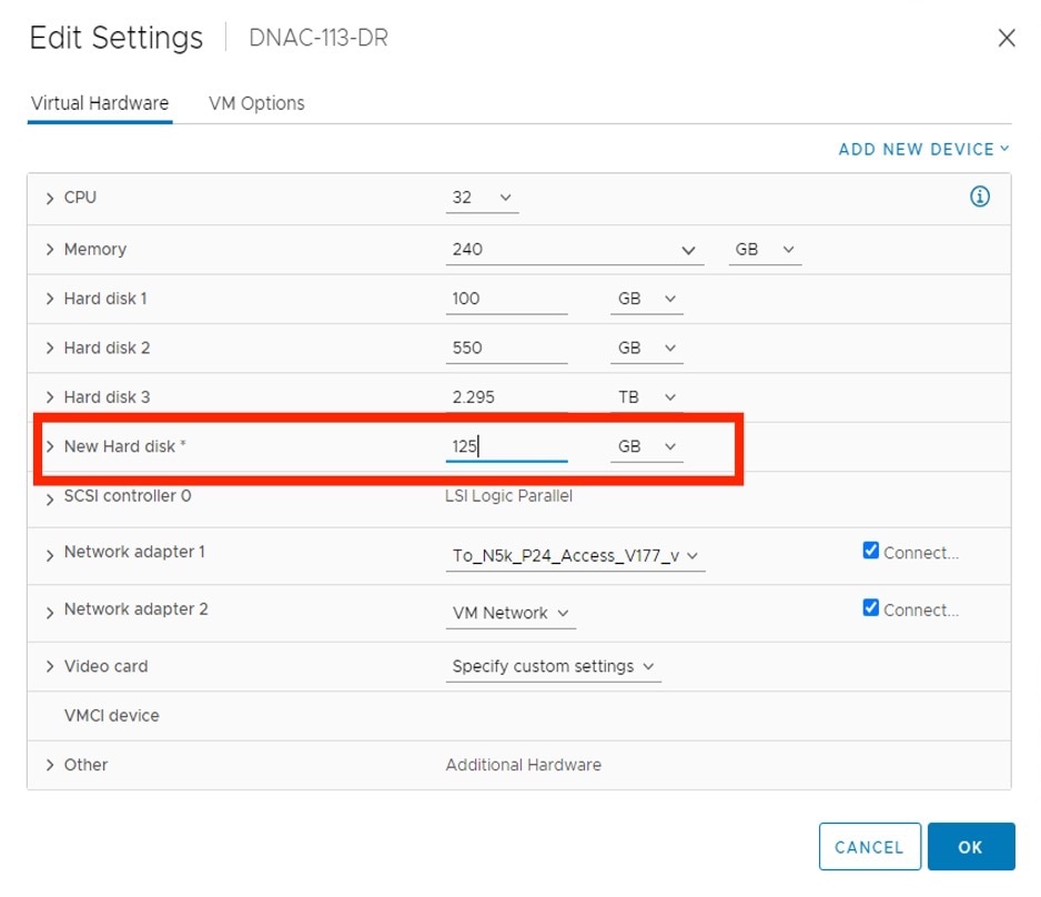
|
||
|
Step 6 |
Click OK. |
||
|
Step 7 |
Power on the appliance's virtual machine. 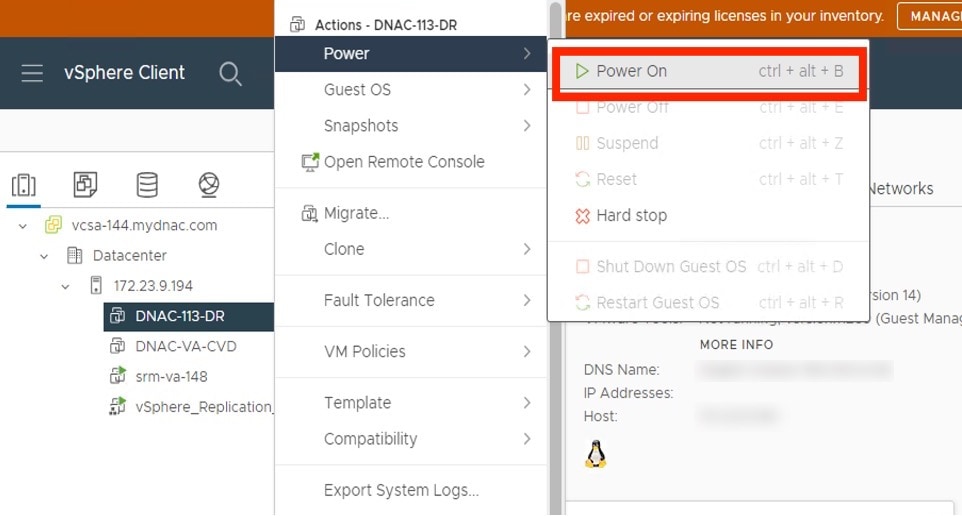
|
What to do next
You can now configure the added physical disk for backup. For information on how to configure the physical disk, see Configure the Location to Store Backup Files.
Add the NFS Server
Catalyst Center allows you to add multiple Network File System (NFS) servers for backup purposes. Use this procedure to add an NFS server that can be used for the backup operation.
Procedure
|
Step 1 |
From the top-left corner, click the menu icon and choose . |
||
|
Step 2 |
Click the Add NFS link. |
||
|
Step 3 |
In the Add NFS slide-in pane, do the following:
|
||
|
Step 4 |
Click View NFS to view the available NFS servers. 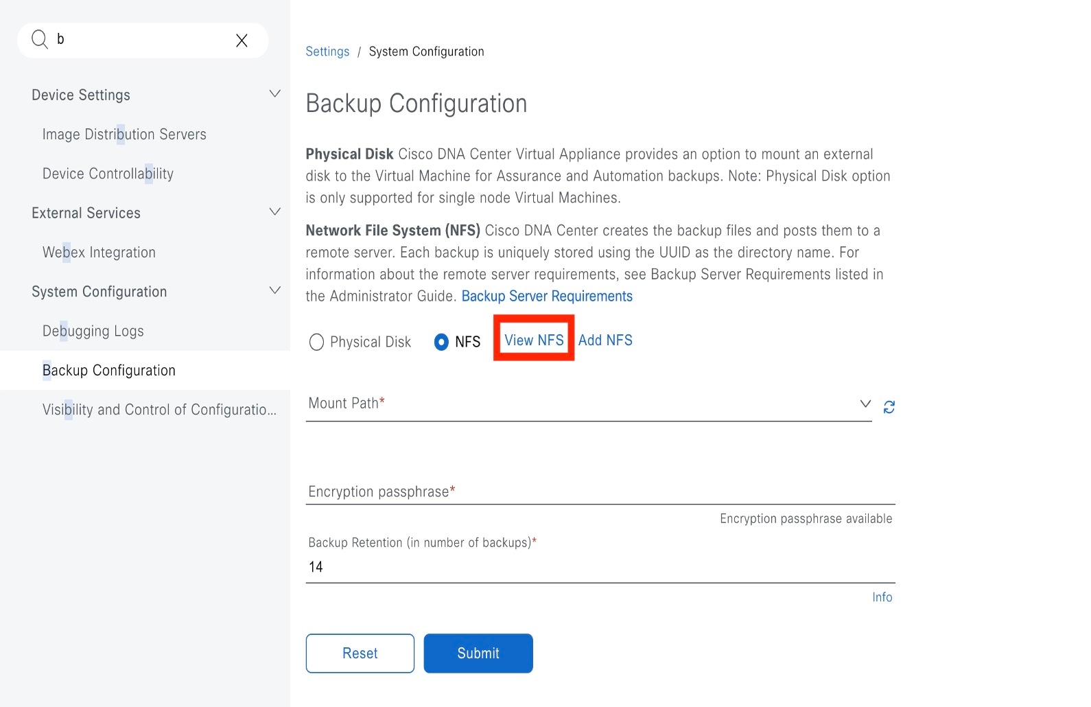
The NFS slide-in pane displays the list of NFS servers, along with details. 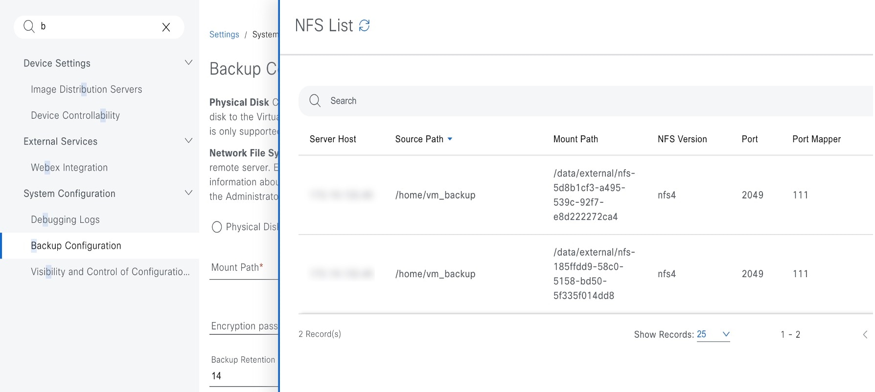
|
||
|
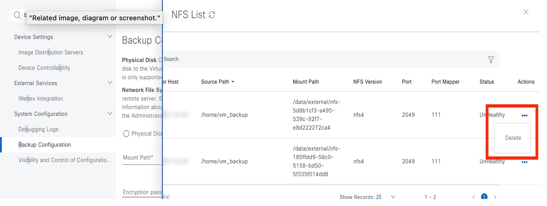
Step 5 |
In the NFS slide-in pane, click the ellipsis under Actions to Delete the NFS server.
|
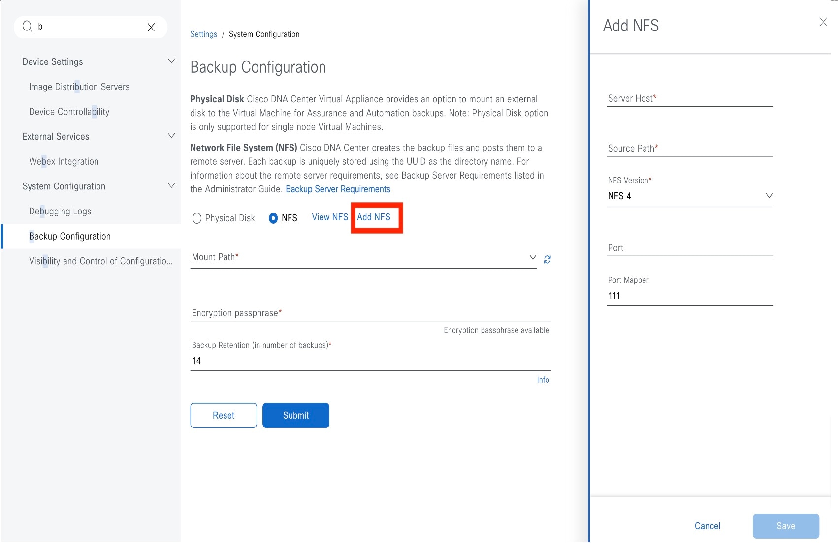
What to do next
Configure the added NFS server for backup. For more information, see Configure the Location to Store Backup Files.
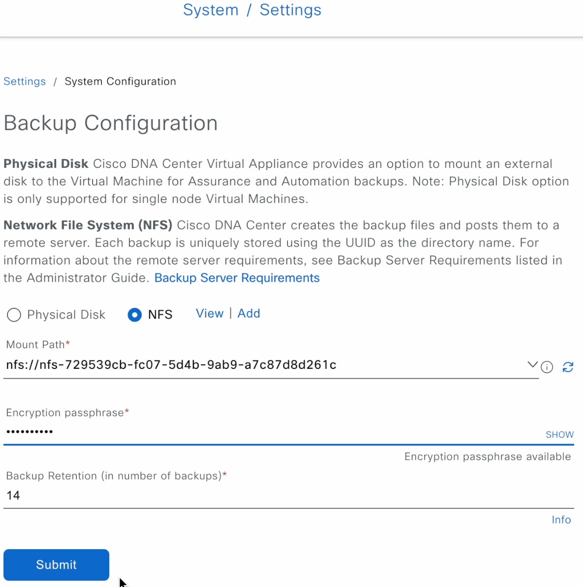
Configure the Location to Store Backup Files
Catalyst Center allows you to configure backups for automation and Assurance data.
Use this procedure to configure the storage location for backup files.
Before you begin
Make sure that the following requirements are met:
-
Only a user with SUPER-ADMIN-ROLE permissions can perform this procedure.
-
The data backup server must meet the requirements described in NFS Backup Server Requirements.
Procedure
|
Step 1 |
From the top-left corner, click the menu icon and choose . You can choose a physical disk or NFS server as your backup location.  |
||||||||||
|
Step 2 |
Physical Disk: Catalyst Center provides an option to mount an external disk to the virtual machine, to store a backup copy of Assurance and automation data. To configure a physical disk, click the Physical Disk radio button and define the following settings:
|
||||||||||
|
Step 3 |
NFS: Catalyst Center creates the backup files and posts them to a remote NFS server. For information about the remote server requirements, see NFS Backup Server Requirements. To configure an NFS backup server, click the NFS radio button and define the following settings:
|
||||||||||
|
Step 4 |
Click Submit. After the request is submitted, you can view the configured physical disk or NFS server under . |
Create a Backup
Use this procedure to create a backup of your virtual appliance.
Before you begin
Procedure
|
Step 1 |
From the Catalyst Center on ESXi menu, choose . 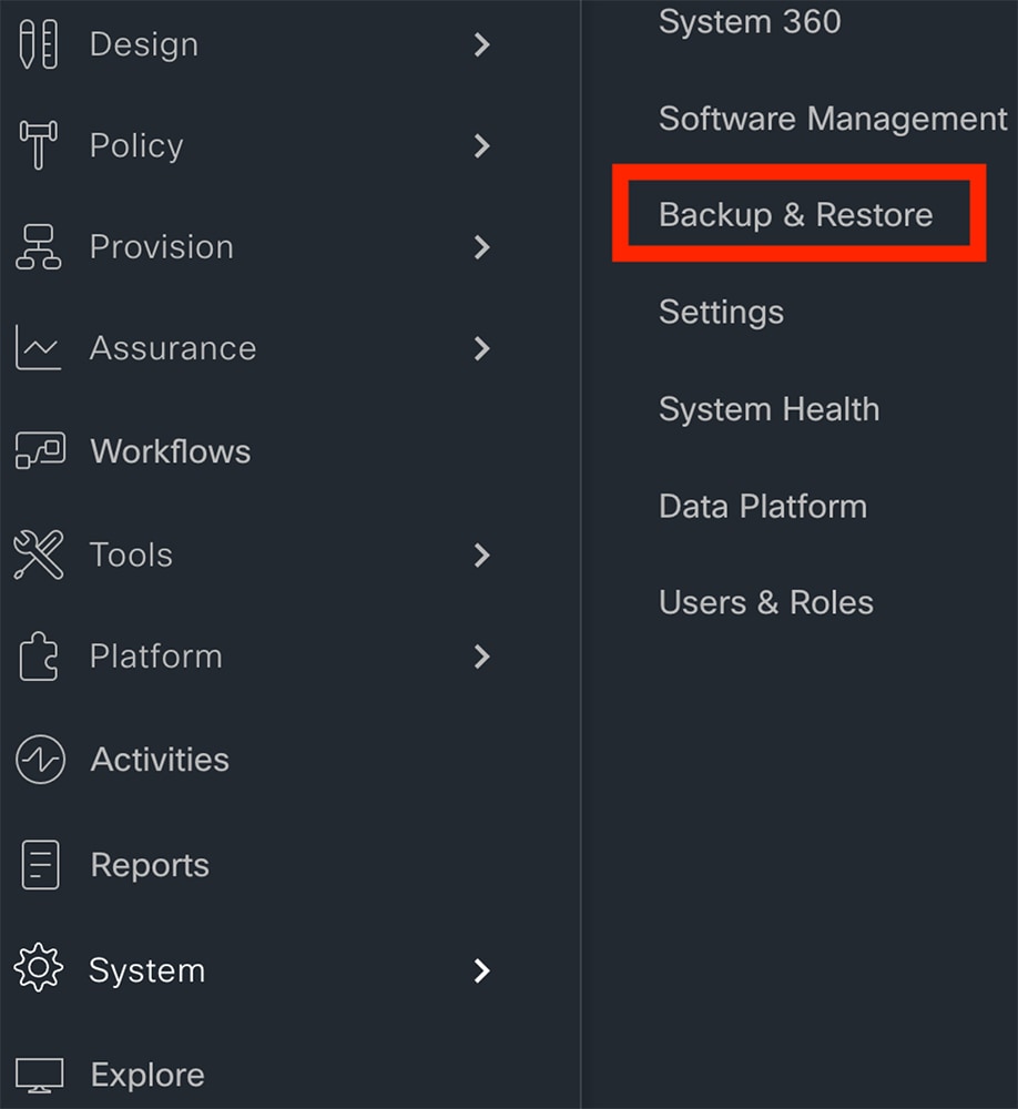 |
|
Step 2 |
Click Create Backup Now. 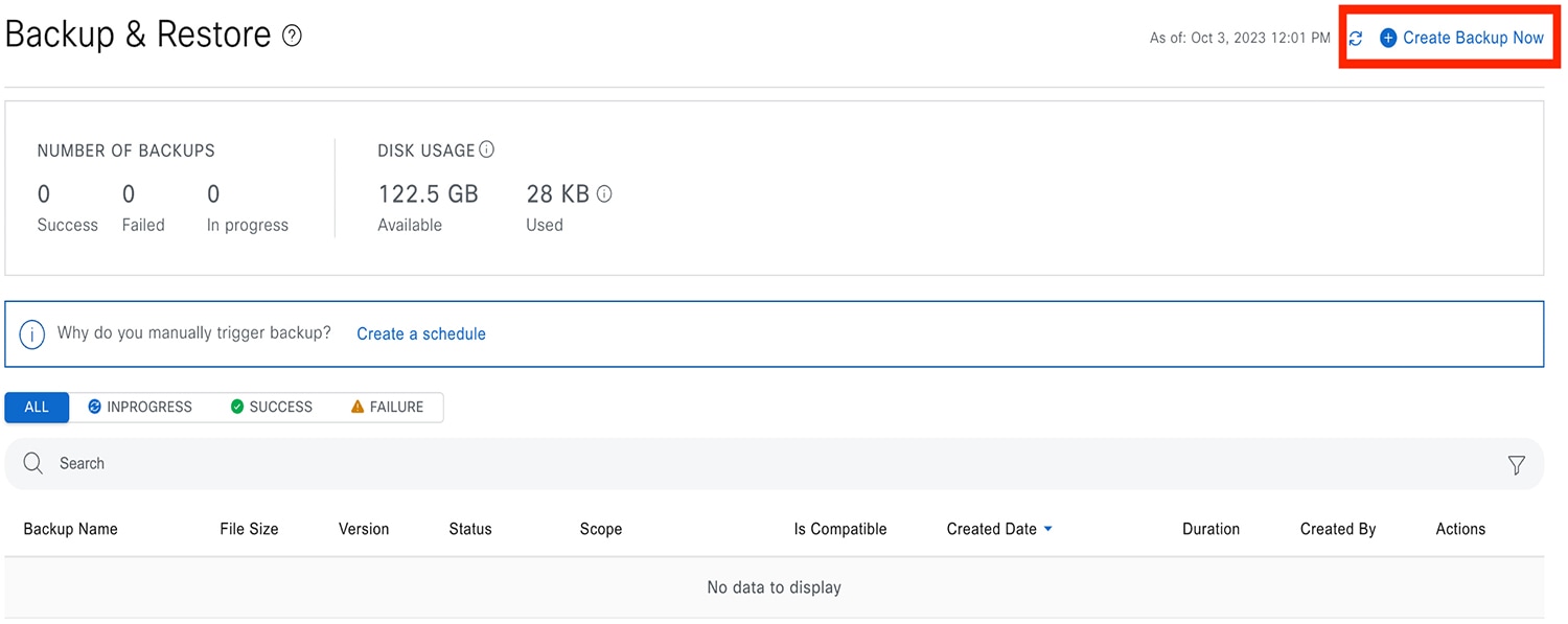 The Create Backup Now slide-in pane opens. |
|
Step 3 |
Enter a unique name for the backup, then click Save. 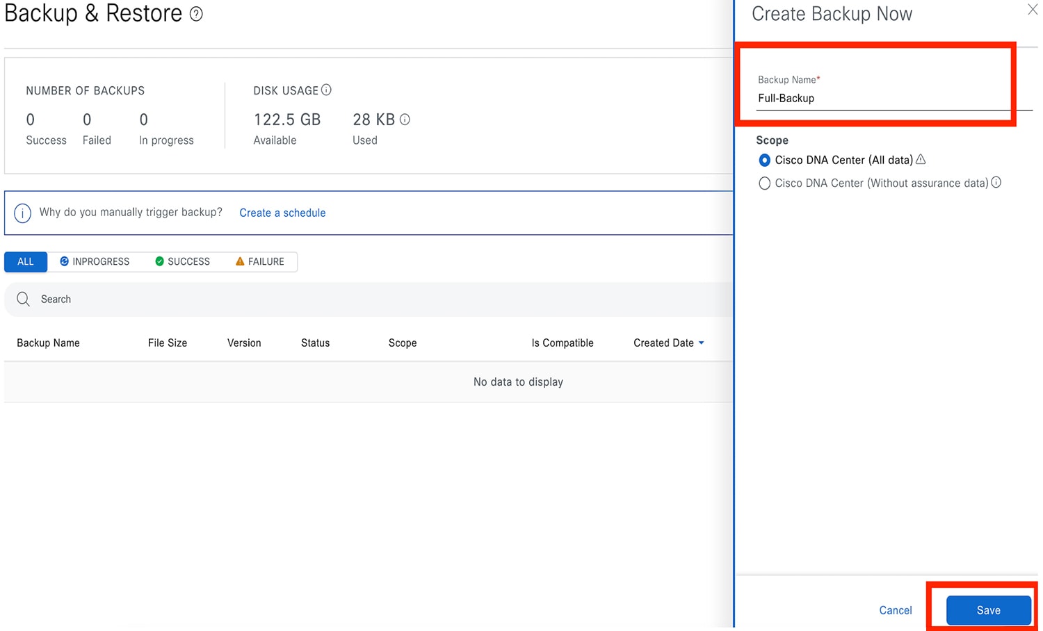 Catalyst Center on ESXi begins the backup process. An entry for the backup is added to the Backup & Restore window's table.  To view details regarding the backup's status, click the ellipsis, and then choose View Status. 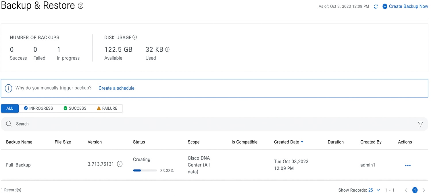 When the backup is complete, its status changes from 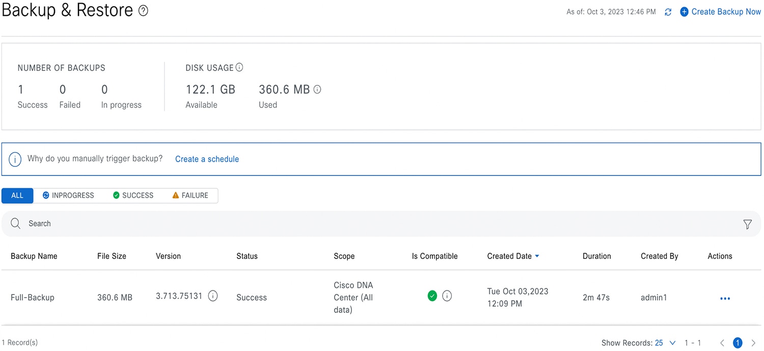 |
Restore Data from Backups
 Caution |
The Catalyst Center restore process restores only the database and files. The restore process does not restore your network state or any changes that were made since the last backup, including any new or updated network policies, passwords, certificates, or trustpool bundles. |
Before you begin
Make sure that the following requirements are met:
-
Only a user with SUPER-ADMIN-ROLE permissions can perform this procedure.
-
You have backups from which to restore data.
When you restore data, Catalyst Center on ESXi enters maintenance mode, and is unavailable until the restore process is completed. Make sure you restore data at a time when Catalyst Center on ESXi can be unavailable.
Procedure
|
Step 1 |
From the top-left corner, click the menu icon and choose . If you have created a backup, it appears in the Backup & Restore window. |
|
Step 2 |
In the Backup Name column, locate the backup that you want to restore. |
|
Step 3 |
In the Actions column, click the ellipsis and choose Restore. 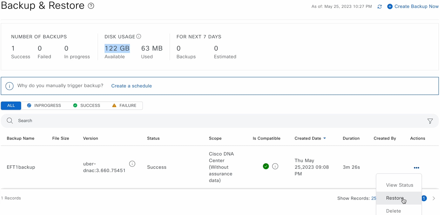 |
|
Step 4 |
In the Restore Backup dialog box, enter the Encryption Passphrase that you used while configuring the backup location and click Restore. 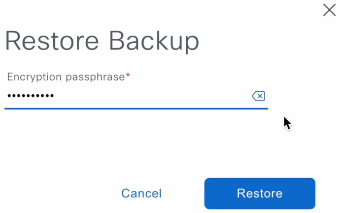 The appliance goes into maintenance mode and starts the restore process.  When the restore operation is complete, its status in the Backup & Restore window table changes to |
|
Step 5 |
After the restore operation completes, click Log In to log back in to Catalyst Center on ESXi. 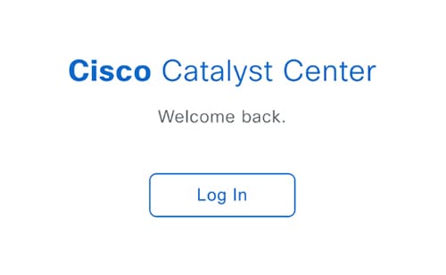 |
|
Step 6 |
Enter the admin user's username and password, then click Login. 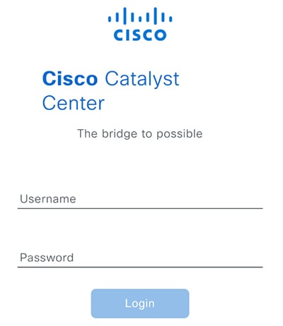 |
Restore Data from a Physical Disk for a Faulty Virtual Appliance
Use this procedure to restore data from a physical disk for a virtual appliance that has failed or is faulty.
Procedure
|
Step 1 |
For your new virtual appliance, do the following to configure Catalyst Center on ESXi to use the storage disk that you configured for the faulty virtual appliance:
It takes approximately 45 minutes for all the services to restart.
|
||
|
Step 2 |
To configure the storage location for the backup, do the following:
|
||
|
Step 3 |
To restore the backup, do the following:
|
Restore Data from an NFS Server for a Faulty Virtual Appliance
Use this procedure to restore data from an NFS server for a virtual appliance that has failed or is faulty.
Procedure
|
Step 1 |
For your new virtual appliance, do the following to configure Catalyst Center on ESXi to use the NFS server that you configured for the faulty virtual appliance:
|
|
Step 2 |
To restore the backup, do the following:
|
Schedule Data Backup
You can schedule recurring backups and define the day of the week and the time of day when they will occur.
Before you begin
Make sure that the following requirements are met:
-
Only a user with SUPER-ADMIN-ROLE permissions can perform this procedure.
-
The data backup server must meet the requirements described in NFS Backup Server Requirements.
-
Backup servers have been configured in Catalyst Center. For more information, see Configure the Location to Store Backup Files.
Procedure
|
Step 1 |
From the top-left corner, click the menu icon and choose . The Backup & Restore window is displayed.
|
||
|
Step 2 |
Click the Create a Schedule link.
|
||
|
Step 3 |
In the Create Schedule slide-in pane, do the following:
The Backup & Restore window displays a banner message that shows the day and time for which the backup is scheduled.
|
||
|
Step 4 |
(Optional) Click the ellipsis at the end of the banner message to do the following:
|
||
|
Step 5 |
After the backup starts, it appears in the Backup & Restore window. To view the list of steps executed, click the ellipsis under Actions and choose View Status. You can also view the backup status under the Status column. |
||
|
Step 6 |
In the Backup & Restore window, click the In Progress, Success, or Failure tab to filter the list of backups to show only those tasks with a status of In Progress, Success, or Failure. During the backup process, Catalyst Center creates the backup database and files. The backup files are saved to the specified location. You are not limited to a single set of backup files, but can create multiple backup files that are identified with their unique names. The status of the backup job changes from In Progress to Success when the process is finished.
|
View the Status of the Backup and Restore
You can view the success or failure status of backup and restore operations.
Procedure
|
Step 1 |
From the top-left corner, click the menu icon and choose . The Backup & Restore window is displayed.
|
|
Step 2 |
Under Actions for a specific backup, click the ellipsis and choose View Status. The Task Details window shows the status and other details.
|
Manage Applications
Catalyst Center provides many of its functions as individual applications, packaged separately from the core infrastructure. This enables you to install and run the applications that you want and uninstall those you are not using, depending on your preferences.
The number and type of application packages shown in the Software Management window vary depending on your Catalyst Center version and your Catalyst Center licensing level. All the application packages that are available to you are shown, whether or not they are currently installed.
Some applications are so basic that they are required on nearly every Catalyst Center deployment. For a description of a package, click the Currently Installed Applications link and place your cursor over its name.
Each Catalyst Center application package consists of service bundles, metadata files, and scripts.
Note |
Perform all application management procedures from the Catalyst Center GUI. Although you can perform many of these procedures using the CLI (after logging in to the shell), we do not recommend this. In particular, if you use the CLI to deploy or upgrade packages, you must ensure that no deploy or upgrade command is entered unless the results of the maglev package status command show all the packages as NOT_DEPLOYED, DEPLOYED, or DEPLOYMENT_ERROR. Any other state indicates that the corresponding activity is in progress, and parallel deployments or upgrades are not supported. |
Download the Latest System Version
The Software Management window indicates the latest Catalyst Center version available.
Complete the following procedure to download the packages for the latest system version.
Before you begin
Only a user with SUPER-ADMIN-ROLE permissions can perform this procedure.
Procedure
|
Step 1 |
From the top-left corner, click the menu icon and choose .
 |
||
|
Step 2 |
If the window indicates that a system update is available, click Download to download the system update.  |
||
|
Step 3 |
Check the check box for the optional packages you want to install, then click Download. 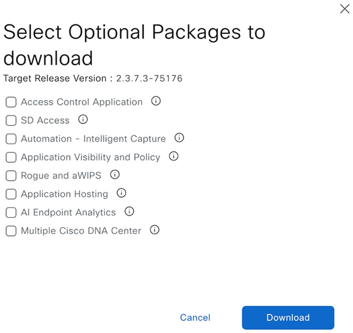 A download progress bar is displayed at the top of the Software Management window.  |
||
|
Step 4 |
Hover your cursor over the ellipsis to the right of the progress bar to access the following options:
|
Upgrade to the Latest System Version
The Software Management window indicates the latest Catalyst Center version available.
Complete the following procedure to upgrade to the latest system version.
Before you begin
Only a user with SUPER-ADMIN-ROLE permissions can perform this procedure.
Procedure
|
Step 1 |
From the top-left corner, click the menu icon and choose .
|
||
|
Step 2 |
If the window indicates that a system update is available, click Upgrade. 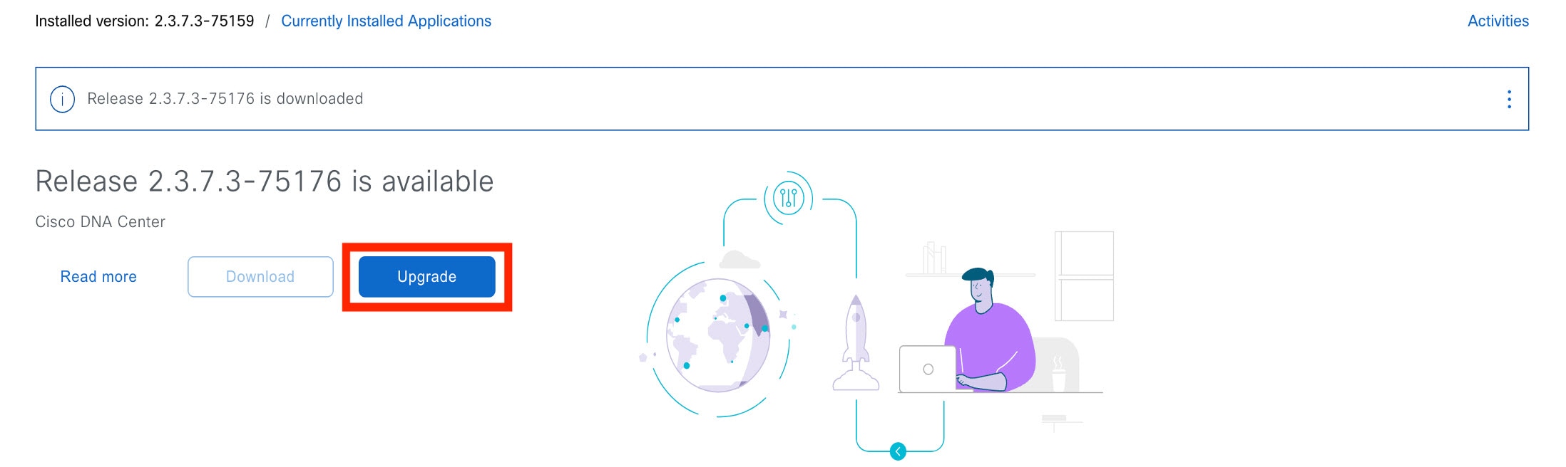 |
||
|
Step 3 |
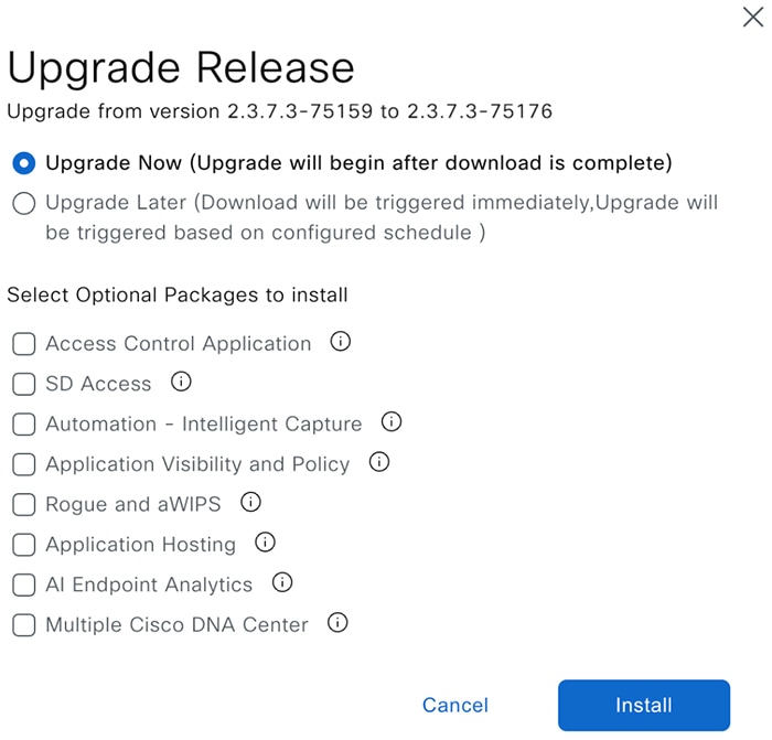
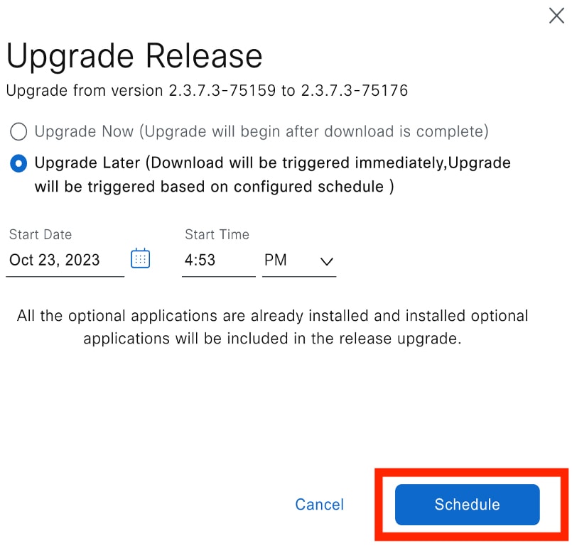
Do one of the following in the Upgrade Release dialog box:
|
||
|
Step 4 |
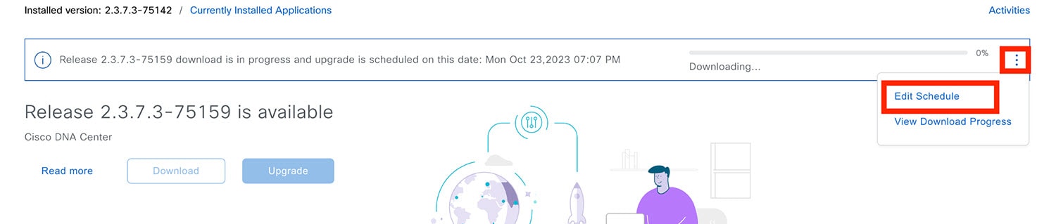
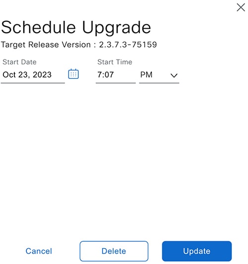
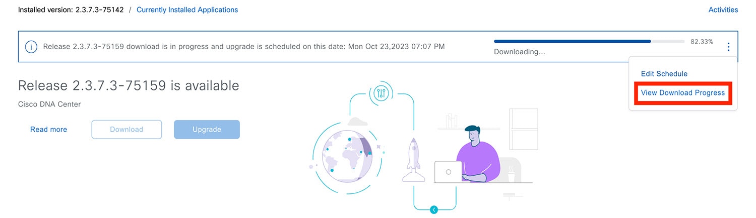
Hover your cursor over the ellipsis to the right of the progress bar to access the following options:
After the system upgrade is complete, a message at the top of the window indicates that your system is up to date. |
||
|
Step 5 |
In the Software Management window, click Activities to view a list of changes made to the system. You can view the system upgrade or download details, the applications installed or uninstalled, and a timestamp of the activity. 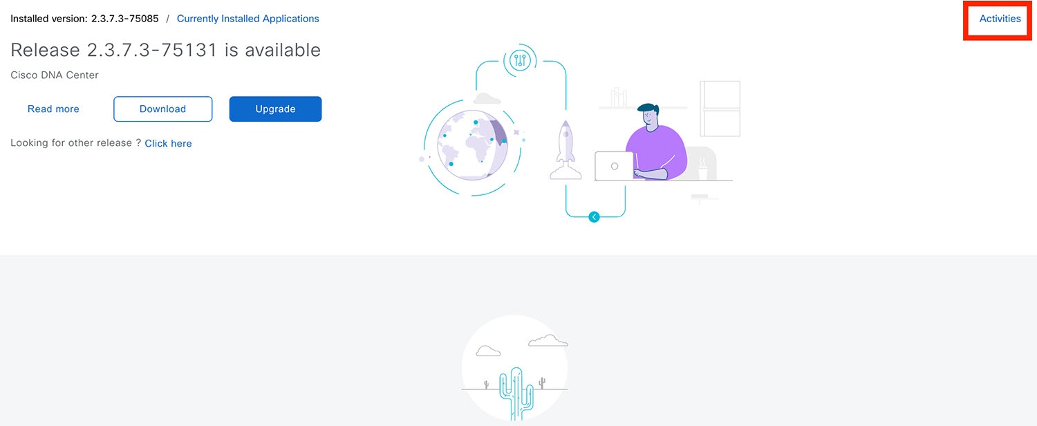 |
||
|
Step 6 |
Under the Actions column, click the ellipsis to view the tasks that occurred during the execution of the activity. 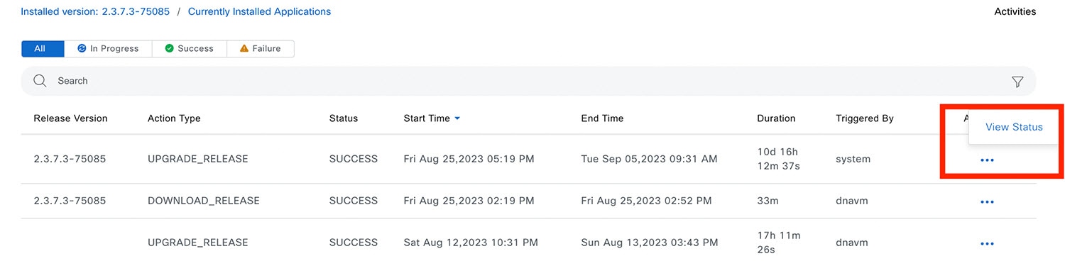 |
Download and Install the Latest System Version in Air Gap Mode
The system upgrade is completed by connecting to the internet and using the online update process. However, in some cases, the upgrade is maintained strictly within internal networks (that is, within an air-gapped environment). This upgrade may be necessary to support additional security or regulatory requirements.
Note |
With the Air Gap mode enabled, you can do the following:
|
Before you begin
Air Gap mode must be enabled on the cluster. For information about how to enable Air Gap mode, see the Cisco Catalyst Center Air Gap Deployment Guide.
Procedure
|
Step 1 |
From the top-left corner, click the menu icon and choose . |
||||||
|
Step 2 |
Access the air gap directory on the restricted shell and copy the air gap tarball from the predetermined location using the following SCP command: If it is a three-node cluster, you can copy the file to any node. |
||||||
|
Step 3 |
In the top-right corner of the Software Management window, click Scan to view the latest available software release. |
||||||
|
Step 4 |
To download the files and schedule the upgrade for a later time, do the following: |
||||||
|
Step 5 |
To download the latest version and upgrade the system immediately, do the following:
After the system upgrade is complete, a message at the top of the window indicates that your system is up to date.
|
Download and Install Application Updates
Catalyst Center treats individual applications as separate from the core infrastructure. Specifically, individual packages for applications can be installed to run on Catalyst Center.
Packages for applications may take time to install and deploy. Therefore, install the packages during a maintenance period for your network.
Before you begin
Only a user with SUPER-ADMIN-ROLE permissions can perform this procedure.
Procedure
|
Step 1 |
From the top-left corner, click the menu icon and choose .
|
||
|
Step 2 |
If any application updates are available, they are displayed at the bottom of the window. Do one of the following:
 |
||
|
Step 3 |
Click Install.
 The window displays a progress bar for each application that's being updated. |
||
|
Step 4 |
Click the Currently Installed Applications link and confirm that the applications you selected have been updated. |
||
|
Step 5 |
In the Software Management window, click Activities to view a list of changes made to the system. You can view the system upgrade or download details, the applications installed or uninstalled, and a timestamp of the activity.  |
||
|
Step 6 |
Under the Actions column, click the ellipsis to view the tasks that occurred during the execution of the activity. 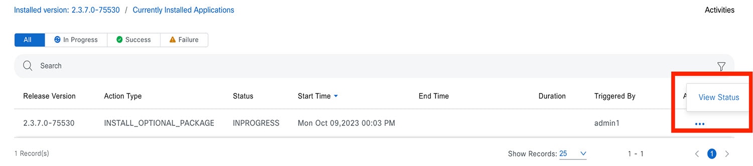 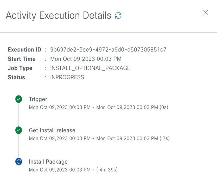 |
Uninstall an Application
Catalyst Center treats individual applications as separate from the core infrastructure. Specifically, individual packages for applications can be uninstalled from Catalyst Center.
You can uninstall only packages for applications that are not system critical.
Before you begin
Only a user with SUPER-ADMIN-ROLE permissions can perform this procedure.
Procedure
|
Step 1 |
From the top-left corner, click the menu icon and choose . |
||
|
Step 2 |
Click the Currently Installed Applications link to view all the applications that are installed on your Catalyst Center appliance. 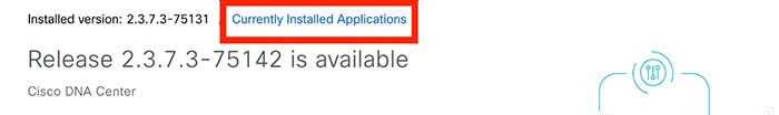 |
||
|
Step 3 |
Check the package you want to remove and click Uninstall.
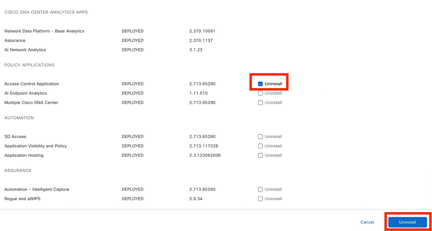 Catalyst Center displays a message after the application has been removed. |
Manage Users
A user profile defines the login, password, and role (permissions) of a user.
You can configure both internal and external profiles for users. Internal user profiles reside in Catalyst Center, and external user profiles reside on an external AAA server.
A default user profile with SUPER-ADMIN-ROLE permissions is created when you install Catalyst Center.
About User Roles
Users are assigned user roles that specify the functions that they are permitted to perform:
-
Administrator (SUPER-ADMIN-ROLE): Users with this role have full access to all of the Catalyst Center functions. They can create other user profiles with various roles, including those with the SUPER-ADMIN-ROLE.
-
Network Administrator (NETWORK-ADMIN-ROLE): Users with this role have full access to all of the network-related Catalyst Center functions. However, they do not have access to system-related functions, such as backup and restore.
-
Observer (OBSERVER-ROLE): Users with this role have view-only access to the Catalyst Center functions. Users with an observer role cannot access any functions that configure or control Catalyst Center or the devices it manages.
Create an Internal User
You can create a user and assign this user a role.
Before you begin
Only a user with SUPER-ADMIN-ROLE permissions can perform this procedure.
Procedure
|
Step 1 |
From the top-left corner, click the menu icon and choose . 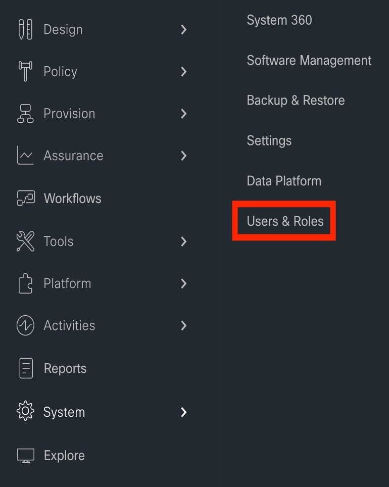
|
|
Step 2 |
Click Add. 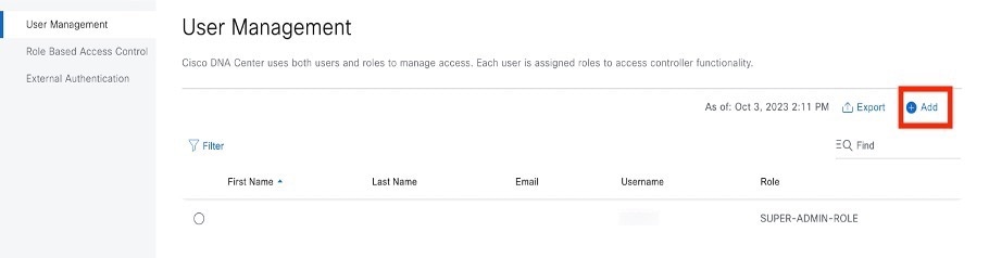
|
|
Step 3 |
Enter a first name, last name, email address, and username for the new user. The email address must meet the requirements for the standard Apache EmailValidator class. 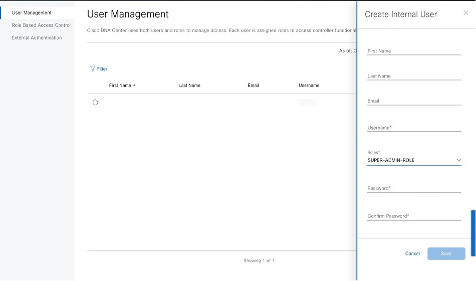
|
|
Step 4 |
Under Role List, choose one of the following roles: SUPER-ADMIN-ROLE, NETWORK-ADMIN-ROLE, or OBSERVER-ROLE. 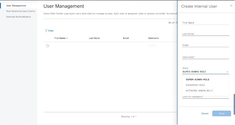
|
|
Step 5 |
Enter a password and confirm it. The password must contain:
|
|
Step 6 |
Click Save. 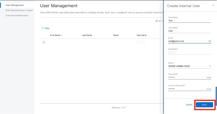
|
Edit a User
You can edit some user properties (but not the username).
Before you begin
Only a user with SUPER-ADMIN-ROLE permissions can perform this procedure.
Procedure
|
Step 1 |
From the top-left corner, click the menu icon and choose . |
|
Step 2 |
Click the radio button next to the user that you want to edit. |
|
Step 3 |
Click Edit. 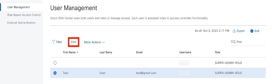
|
|
Step 4 |
Edit the first or last name or email address, if needed. |
|
Step 5 |
Under Role List, choose a new role, if needed: SUPER-ADMIN-ROLE, NETWORK-ADMIN-ROLE, or OBSERVER-ROLE. |
|
Step 6 |
Click Save. |
Delete a User
Before you begin
Only a user with SUPER-ADMIN-ROLE permissions can perform this procedure.
Procedure
|
Step 1 |
From the top-left corner, click the menu icon and choose . |
|
Step 2 |
Click the radio button next to the user that you want to delete. |
|
Step 3 |
Click Delete. 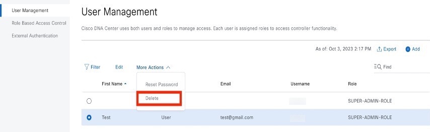
|
|
Step 4 |
At the confirmation prompt, click Continue. |
Reset a User Password
You can reset another user's password.
For security reasons, passwords are not displayed to any user, not even to the users with administrator privileges.
Before you begin
Only a user with SUPER-ADMIN-ROLE permissions can perform this procedure.
Procedure
|
Step 1 |
From the top-left corner, click the menu icon and choose . |
|
Step 2 |
Click the radio button next to the user whose password you want to reset. |
|
Step 3 |
From the More Actions drop-down list, click Reset Password. 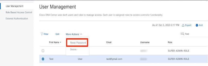
|
|
Step 4 |
Enter a new password and confirm it. The new password must contain:
|
|
Step 5 |
Click Save. |
Change Your Own User Password
Before you begin
Only a user with SUPER-ADMIN-ROLE permissions can perform this procedure. For more information, see About User Roles.
Procedure
|
Step 1 |
From the top-left corner, click the menu icon and choose . |
|
Step 2 |
Enter information in the required fields. |
|
Step 3 |
Click Update. |
Change Your Own User Password Without Admin Permission
The following procedure describes how to change your password without admin permission.
Procedure
|
Step 1 |
From the top-right corner, click your displayed username and choose . 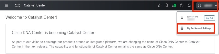
|
|
Step 2 |
In the Password field, click Update Password. 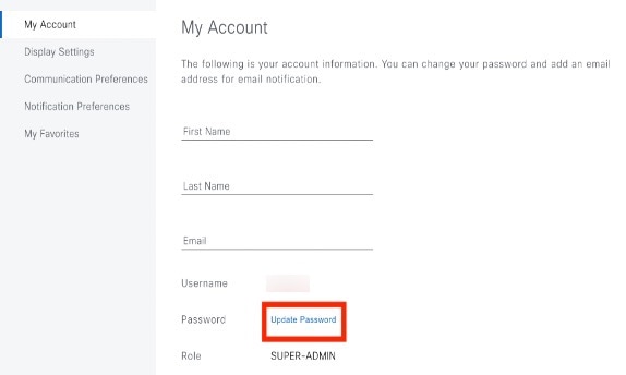
|
|
Step 3 |
In the Update Password dialog box, enter the new password and confirm the new password. 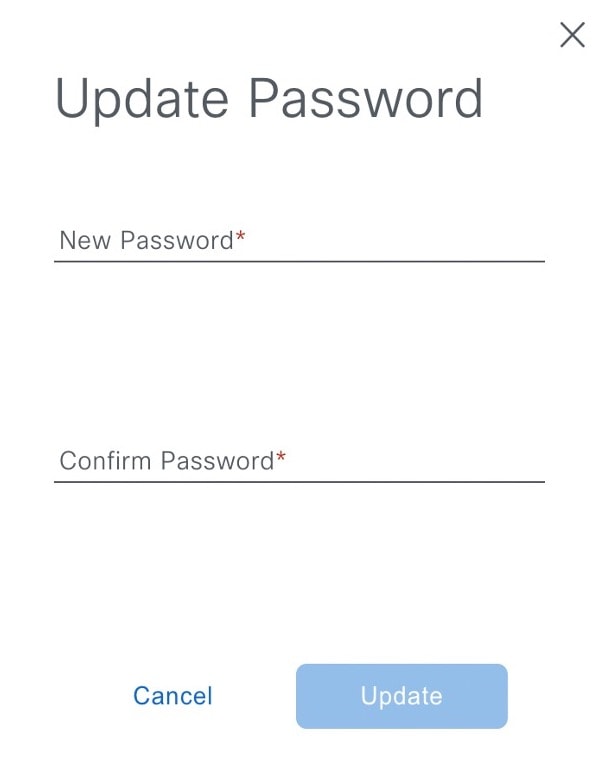
|
|
Step 4 |
Click Update. |
Reset a Forgotten Password
If you forgot your password, contact the Cisco Technical Assistance Center (TAC) to reset it.
Configure Role-Based Access Control
Catalyst Center supports role-based access control (RBAC), which enables a user with SUPER-ADMIN-ROLE privileges to define custom roles that permit or restrict user access to certain Catalyst Center functions.
Use this procedure to define a custom role and then assign a user to that role.
Before you begin
Only a user with SUPER-ADMIN-ROLE permissions can perform this procedure.
Procedure
|
Step 1 |
Define a custom role.
|
|
Step 2 |
To assign a user to the custom role you just created, click Add Users. 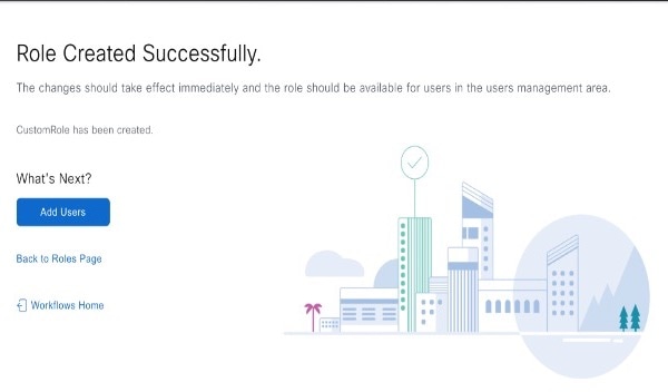
The User Management window opens, which allows you to assign the custom role to an existing user or to a new user.
|
|
Step 3 |
If you are an existing user who was logged in when the administrator was updating your access permissions, you must log out of Catalyst Center and then log back in for the new permission settings to take effect. |
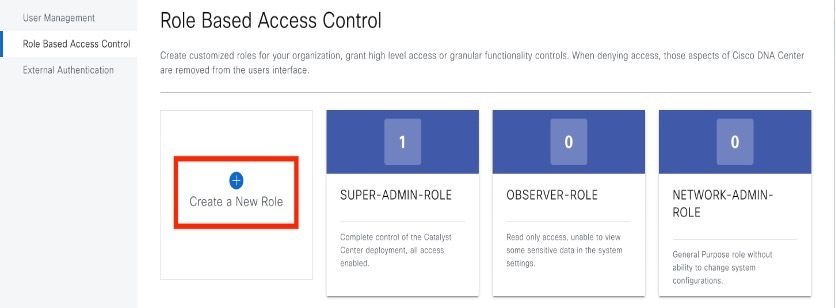
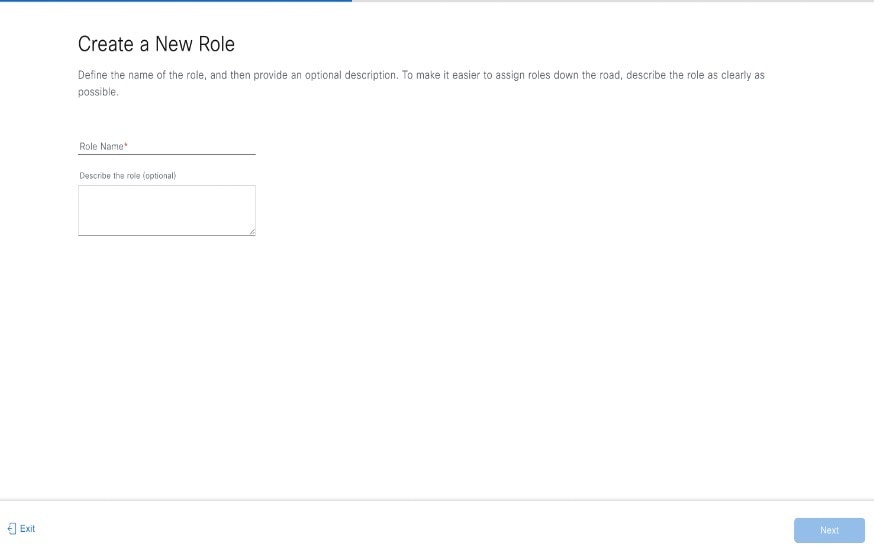
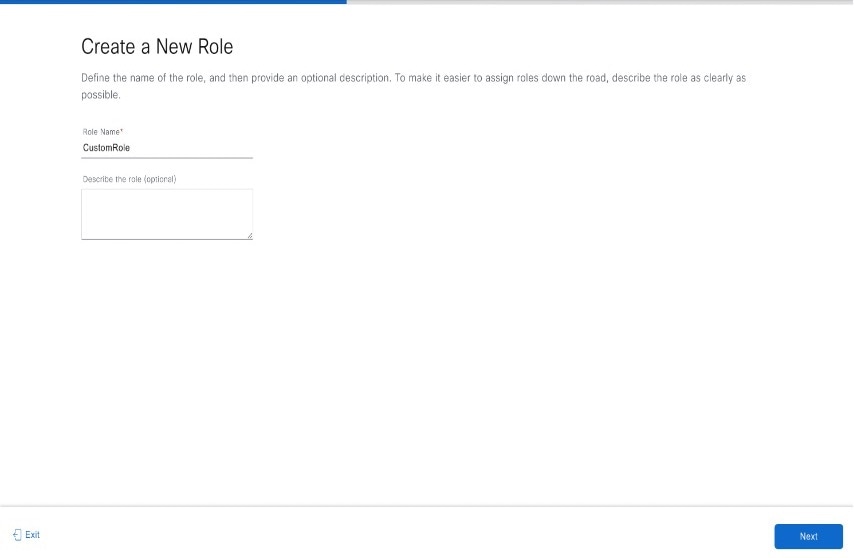
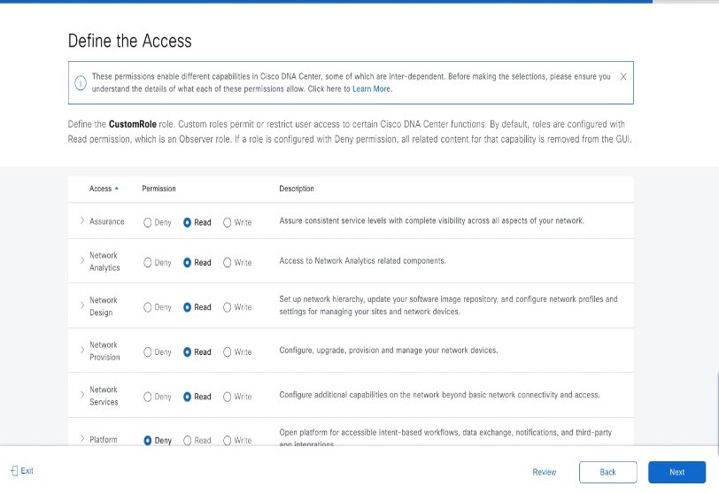
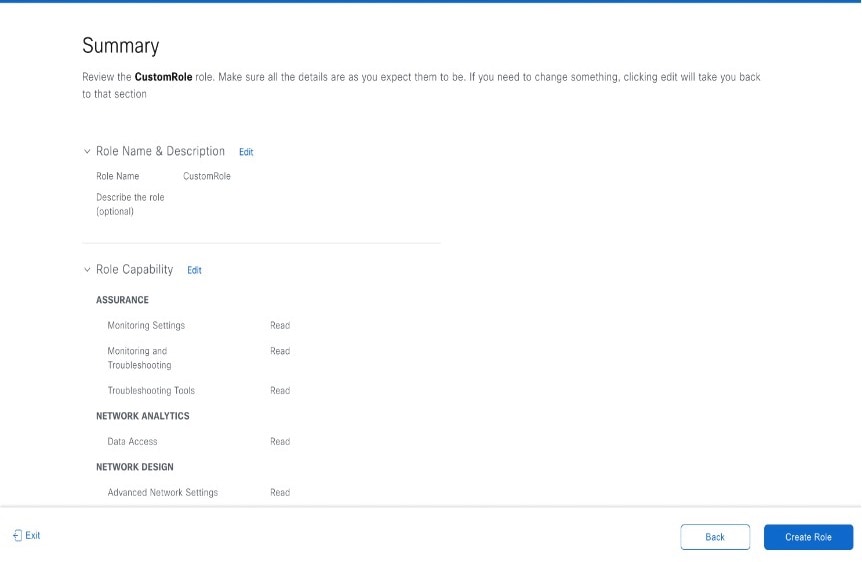
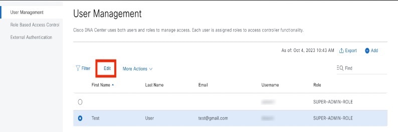
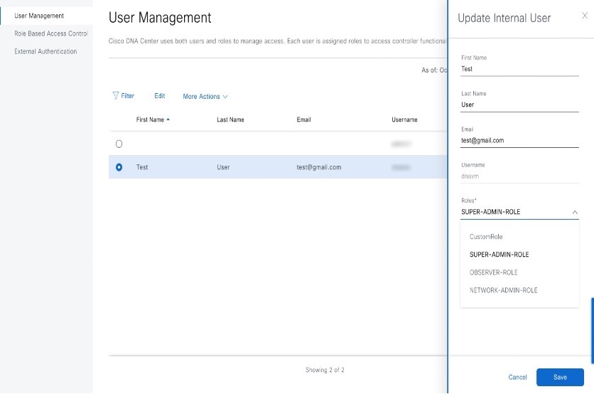
Catalyst Center User Role Permissions
| Capability | Description |
|---|---|
|
Assurance |
Assure consistent service levels with complete visibility across all aspects of your network. |
|
Monitoring and Troubleshooting |
Monitor and manage the health of your network with issue troubleshooting and remediation, proactive network monitoring, and insights driven by AI Network Analytics. This role lets you:
|
|
Monitoring Settings |
Configure and manage issues. Update network, client, and application health thresholds. Note: You must have at least Read permission on Monitoring and Troubleshooting. |
|
Troubleshooting Tools |
Create and manage sensor tests. Schedule on-demand forensic packet captures (Intelligent Capture) for troubleshooting clients. Note: You must have at least Read permission on Monitoring and Troubleshooting. |
|
Network Analytics |
Manage network analytics-related components. |
|
Data Access |
Enable access to query engine APIs. Control functions such as global search, rogue management, and aWIPS. Note: Setting the permission to Deny affects Search and Assurance functionality. |
|
Network Design |
Set up the network hierarchy, update your software image repository, and configure network profiles and settings for managing your sites and network devices. |
|
Advanced Network Settings |
|
|
Image Repository |
Manage software images and facilitate upgrades and updates on physical and virtual network entities. |
|
Network Hierarchy |
Define and create a network hierarchy of sites, buildings, floors, and areas based on geographic location. Users with this role can also add CMX servers in . |
|
Network Profiles |
Create network profiles for routing, switching, and wireless. Assign profiles to sites. This role includes CLI Templates, Tagging, Feature Templates, and Authentication Template. Note: To create SSIDs, you must have Write permission on Network Settings. |
|
Network Settings |
Common site-wide network settings such as AAA, NTP, DHCP, DNS, Syslog, SNMP, and Telemetry. Users with this role can add an SFTP server and modify the Network Resync Interval in . Note: To create wireless profiles, you must have Write permission on Network Profiles. To assign a CMX server to a site, building, or floor, you must have Write permission on Network Hierarchy. |
|
Virtual Network |
Manage virtual networks (VNs). Segment physical networks into multiple logical networks for traffic isolation and controlled inter-VN communication. |
|
Network Provision |
Configure, upgrade, provision, and manage your network devices. |
|
Compliance |
Manage compliance provisioning. |
|
EoX |
Scan the network for details on publicly announced information pertaining to the End of Life, End of Sales, or End of Support of the hardware and software in your network. Note: To view EoX scans, you must have Read permission on Compliance. To run EoX scans, you must have Write permission on Compliance. |
|
Image Update |
Upgrade software images on devices that don't match the Golden Image settings after a complete upgrade lifecycle. |
|
Inventory Management |
Discover, add, replace, or delete devices on your network while managing device attributes and configuration properties. Note: To replace a device, you must have Write permission on . |
|
Inventory Management > Device Configuration |
Device Configuration: Display the running configuration of a device. |
|
Inventory Management > Discovery |
Discovery: Discover new devices in your network. |
|
Inventory Management > Network Device |
Network Device: Add devices from Inventory, view device details, and perform device-level actions. |
|
Inventory Insights: Displays device issues, such as Speed/Duplex settings mismatch and VLAN mismatch, and the number of times each issue occurred. Provides detailed actions for users to perform to revolve the issues. Because this information requires action, including possible configuration changes, it is not displayed to users who have a read-only role. |
|
|
Inventory Management > Port Management |
Port Management: Allow port actions on a device. |
|
Inventory Management > Topology |
Topology: Display network device and link connectivity. Manage device roles, tag devices, customize the display, and save custom topology layouts. Note: To view the SD-Access Fabric window, you must have at least Read permission on . |
|
License |
Unified view of your software and network assets relative to license usage and compliance. The role also controls permissions for cisco.com, Cisco credentials, device EULA, and Smart accounts. |
|
Network Telemetry |
Enable or disable the collection of application telemetry from devices. Deploy related settings, such as site telemetry receivers, wireless service assurance, and controller certificates, to devices. Note: To enable or disable the collection of application telemetry, you must have Write permission on Provision. |
|
PnP |
Automatically onboard new devices, assign them to sites, and configure them with site-specific contextual settings. |
|
Provision |
Provision devices with the site-specific settings and policies that are configured for the network. This role includes Fabric, Application Policy, Application Visibility, Cloud, Site-to-Site VPN, Network/Application Telemetry, Stealthwatch, Sync Start vs Run Configuration, and Umbrella provisioning. On the main dashboards for rogue and aWIPS, you can enable or disable certain actions, including rogue containment. To provision devices, you must have Write permission on Network Design and Network Provision. |
|
Network Services |
Configure additional capabilities on the network beyond basic network connectivity and access. |
|
Application Hosting |
Deploy, manage, and monitor virtualized and container-based applications running on network devices. |
|
Bonjour |
Enable the Wide Area Bonjour service across your network to enable policy-based service discovery. |
|
Stealthwatch |
Configure network elements to send data to Cisco Stealthwatch to detect and mitigate threats, even in encrypted traffic. To provision Stealthwatch, you must have Write permission on the following components: |
|
Umbrella |
Configure network elements to use Cisco Umbrella as the first line of defense against cybersecurity threats. To provision Umbrella, you must have Write permission on the following components: You must also have Read permission on Advanced Network Settings. |
|
Platform |
Open platform for accessible, intent-based workflows, data exchange, notifications, integration settings, and third-party app integrations. |
|
APIs |
Drive value by accessing Catalyst Center through REST APIs. |
|
Bundles |
Enhance productivity by configuring and activating preconfigured bundles for ITSM integration. |
|
Events |
Subscribe to get notified in near real time about network and system events of interest and initiate corrective actions. You can configure email and syslog logs in . |
|
Reports |
Generate reports using predefined reporting templates for all aspects of your network. Generate reports for rogue devices and for aWIPS. You can configure webhooks in . |
|
Security |
Manage and control secure access to the network. |
|
Group-Based Policy |
Manage group-based policies for networks that enforce segmentation and access control based on Cisco security group tags. This role includes Endpoint Analytics. |
|
IP-Based Access Control |
Manage IP-based access control lists that enforce network segmentation based on IP addresses. |
|
Security Advisories |
Scan the network for security advisories. Review and understand the impact of published Cisco security advisories that may affect your network. |
|
System |
Centralized administration of Catalyst Center, which includes configuration management, network connectivity, software upgrades, and more. |
|
Machine Reasoning |
Configure automatic updates to the machine reasoning knowledge base to rapidly identify security vulnerabilities and improve automated issue analysis. |
|
System Management |
Manage core system functionality and connectivity settings. Manage user roles and configure external authentication. This role includes Integrity Verification, HA, Disaster Recovery, Debugging Logs, Product Telemetry, System EULA, IPAM, vManage Servers, Cisco AI Analytics, Backup & Restore, and Data Platform. |
|
Utilities |
One-stop-shop productivity resource for the most commonly used troubleshooting tools and services. |
|
Audit Log |
Detailed log of changes made via UI or API interface to network devices or Catalyst Center. |
|
Event Viewer |
View network device and client events for troubleshooting. |
|
Network Reasoner |
Initiate logical and automated troubleshooting for network issues while drawing on the knowledge wealth of network domain experts. |
|
Remote Device Support |
Allow the Cisco support team to remotely troubleshoot the network devices managed by Catalyst Center. With this role enabled, an engineer from the Cisco Technical Assistance Center (TAC) can connect remotely to a customer's Catalyst Center setup for troubleshooting purposes. |
|
Scheduler |
Integrated with other back-end services, scheduler lets you run, schedule, and monitor network tasks and activities such as deploy policies, provision, or upgrade the network. You can also schedule rogue containment. |
|
Search |
Search for various objects in Catalyst Center, such as sites, network devices, clients, applications, policies, settings, tags, menu items, and more. |
Display Role-Based Access Control Statistics
You can display statistics that show how many users belong to each user role. You can also drill down to view the list of users who have a selected role.
Procedure
|
Step 1 |
From the top-left corner, click the menu icon and choose . All default user roles and custom roles are displayed. |
|
Step 2 |
Click the number corresponding to each user role to view the list of users who have that role. 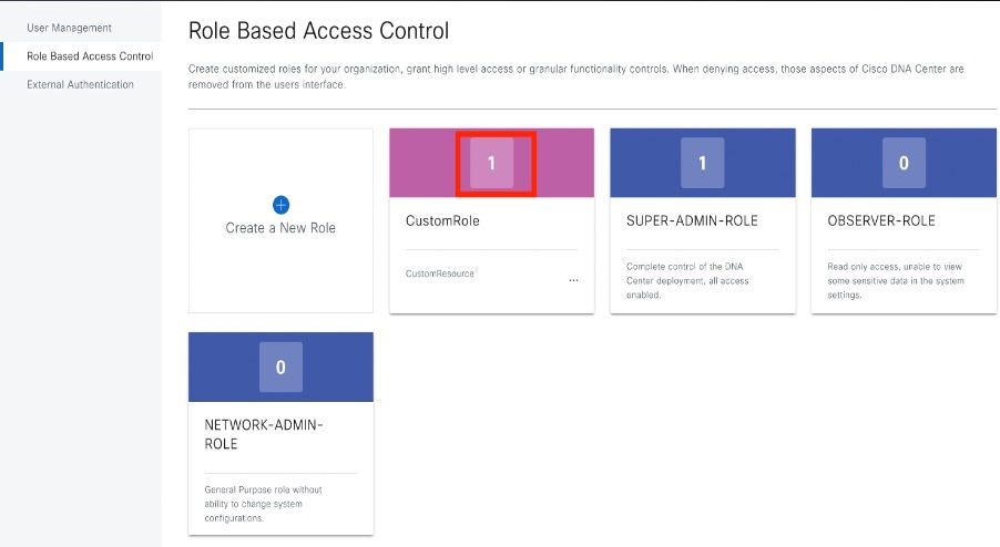
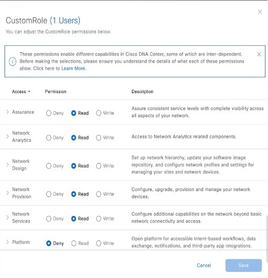
|
Configure External Authentication
If you are using an external server for authentication and authorization of external users, you should enable external authentication in Catalyst Center.
Before you begin
-
Only a user with SUPER-ADMIN-ROLE permissions can perform this procedure.
-
You must configure at least one authentication server.
Note |
In releases earlier than 2.1.x, when external authentication is enabled, Catalyst Center falls back to local users if the AAA server is unreachable or the AAA server rejects an unknown username. In the current release, Catalyst Center does not fall back to local users if the AAA server is unreachable or the AAA server rejects an unknown username. When external authentication fallback is enabled, external users and local admins can log in to Catalyst Center. To enable external authentication fallback, SSH to the Catalyst Center instance and enter the following CLI command: |
Procedure
|
Step 1 |
From the top-left corner, click the menu icon and choose . 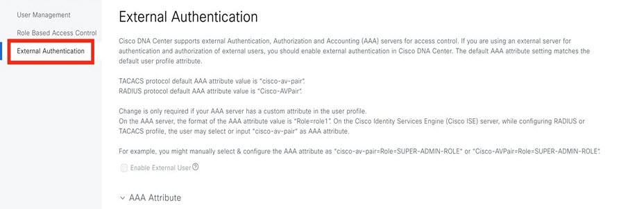 |
||||||||||||||
|
Step 2 |
To enable external authentication in Catalyst Center, check the Enable External User check box. 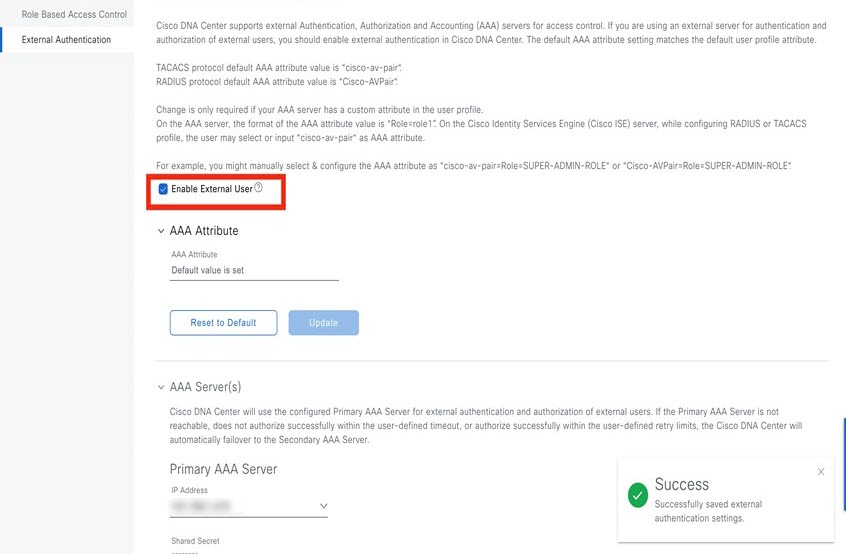 |
||||||||||||||
|
Step 3 |
(Optional) Configure the AAA attribute. For TACACS authentication, the following AAA attributes are supported:
For RADIUS authentication, the following AAA attributes are supported:
|
||||||||||||||
|
Step 4 |
(Optional) Configure the AAA server or servers. Configure these settings only if you want to swap the current primary or secondary AAA servers or define different AAA servers. From the top-left corner, click the menu icon and choose to open the Authentication and Policy Servers window.
|
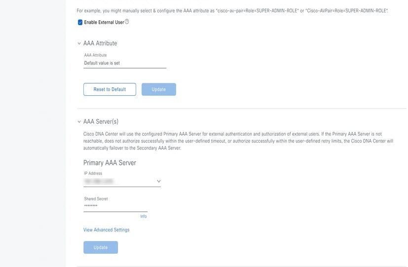
Two-Factor Authentication
Two-factor authentication, also known as 2FA, adds another layer of security to user verification by using an identifier method in addition to a user's name and password. The identifier method is generally something that only the actual intended user possesses (such as a phone app or keyfob) and is intentionally separated from the original login method.
The Catalyst Center implementation of two-factor authentication supports the use of a token client (that generates single-use token codes after the appropriate PIN is entered), a token server (that validates token codes), and an authentication server to manage user access. Authentication can be handled using either the RADIUS or TACACS+ protocol.
Prerequisites for Two-Factor Authentication
The following prerequisites must be in place to set up two-factor authentication for use with Catalyst Center:
-
An authentication server that is able to return attribute-value pairs to convey RBAC role authorizations for authenticated Catalyst Center users. In our example, we use Cisco Identity Services Engine (Cisco ISE) 2.3 Patch 1.
-
A two-factor token server that you will integrate with your authentication server. In our example, we use RSA Authentication Manager 7.2.
-
A token card application on the client’s machine that generates software tokens. In our example, we use RSA SecurID Software Token.
Two-Factor Authentication Workflow
Here is a summary of what happens when a user logs in to a Catalyst Center appliance on which two-factor authentication has been configured:
-
In an RSA SecurID token client, a user enters their PIN to get a token code.
-
In the Catalyst Center login page, they enter their username and token code.
-
Catalyst Center sends the login request to Cisco ISE using either the RADIUS or TACACS+ protocol.
-
Cisco ISE sends the request to the RSA Authentication Manager server.
-
RSA Authentication Manager validates the token code and informs Cisco ISE whether the user has been authenticated successfully.
-
If the user has been authenticated, Cisco ISE matches the authenticated user with their configured authorization profile and returns the role=NETWORK-ADMIN-ROLE attribute-value pair.
-
Catalyst Center grants access to the features and pages associated with the user's role-based access control (RBAC) role.
Configure Two-Factor Authentication
To configure two-factor authentication on your Catalyst Center appliance, complete the following procedure.
Procedure
|
Step 1 |
Integrate RSA Authentication Manager with Cisco ISE: |
||
|
Step 2 |
Create two authorization profiles, one for the Admin user role and one for the Observer user role. |
||
|
Step 3 |
Create an authentication policy for your Catalyst Center appliance. In the Cisco Identity Services Engine Administrator Guide, see the "Configure Authentication Policies" topic. |
||
|
Step 4 |
Create two authorization policies, one for the Admin user role and one for the Observer user role. In the Cisco Identity Services Engine Administrator Guide, see the "Configure Authorization Policies" topic. |
||
|
Step 5 |
In the RSA Authentication Manager Security Console, verify that software tokens have been assigned to both users. For more information, see the "View a Token" topic in the RSA Self-Service Console Help.
|
Enable Two-Factor Authentication Using RADIUS
To enable two-factor authentication that uses a Cisco ISE server configured for RADIUS, complete the following procedure:
Procedure
|
Step 1 |
Integrate Cisco ISE with Catalyst Center. In the Catalyst Center Installation Guide, see the "Integrate Cisco ISE with Catalyst Center" topic. |
||
|
Step 2 |
Configure Catalyst Center to use your Cisco ISE server for authentication. See Configure External Authentication.
|
Enable Two-Factor Authentication Using TACACS+
To enable two-factor authentication that uses a Cisco ISE server configured for TACACS+, complete the following procedure:
Procedure
|
Step 1 |
In Cisco ISE, choose to open the Network Devices window. |
||
|
Step 2 |
Click TACACS Authentication Settings to view its contents. Ensure that a shared secret has already been configured for the Catalyst Center device that you added previously. |
||
|
Step 3 |
Choose to open the TACACS Profiles window. |
||
|
Step 4 |
Create TACACS+ profiles for the example_admin and example_observer user roles: |
||
|
Step 5 |
Integrate Cisco ISE with Catalyst Center. In the Catalyst Center Installation Guide, see the "Integrate Cisco ISE with Catalyst Center" topic. |
||
|
Step 6 |
Configure Catalyst Center to use your Cisco ISE server for authentication. See Configure External Authentication.
|
Log In Using Two-Factor Authentication
To log in to Catalyst Center using two-factor authentication, complete the following procedure:
Procedure
|
Step 1 |
From the Catalyst Center login page, enter the appropriate username. |
|
Step 2 |
Open the RSA SecurID token client and enter the PIN you configured previously to generate a one-time token. |
|
Step 3 |
Copy this token and paste it into the Password field of the Catalyst Center login page. |
|
Step 4 |
Click Log In. |
Display External Users
You can view the list of external users who have logged in through RADIUS or TACACS for the first time. The information that is displayed includes their usernames and roles.
Procedure
|
Step 1 |
From the top-left corner, click the menu icon and choose . |
|
Step 2 |
Scroll to the bottom of the window, where the External Users area lists the external users. |
Migrate from Cisco Prime Infrastructure to Catalyst Center
Before you begin
This section provides an overview about how to migrate from Cisco Prime Infrastructure to Catalyst Center.
-
Using the Cisco Prime Infrastructure Compatibility Matrix, identify the Prime Data Migration Tool (PDMT) release that is compatible with your version of Catalyst Center.
-
Download the compatible PDMT release using the Cisco Software Download Tool.
Procedure
|
Step 1 |
Perform a readiness check using the Catalyst Center Assessment and Readiness Tool for Cisco Prime Infrastructure (PDART). For more information about using PDART, click here. |
|
Step 2 |
Once you have assessed the readiness of the migration, use the PDMT to migrate your sites and devices from Cisco Prime Infrastructure to Catalyst Center. |
Multiple Catalyst Center—Limited Availability
Multiple Catalyst Center allows you to define a single global set of virtual networks for software-defined access across multiple Catalyst Center clusters integrated with a single Cisco ISE system. This Multiple Catalyst Center functionality is a Limited Availability offering in Catalyst Center on ESXi.
To facilitate global administration of Cisco SD-Access across multiple Catalyst Center clusters with a consistent set of virtual networks, the Multiple Catalyst Center feature leverages the existing secure connection with Cisco ISE to propagate virtual networks, Security Group Tags (SGTs), access contracts, and Group-Based Access Control (GBAC) Policy from one cluster to another cluster, all integrated with the same Cisco ISE deployment. Cisco ISE takes the information learned from one cluster (the Author node) and propagates it to the other clusters (Reader nodes).
Because there are significant caveats for the Multiple Catalyst Center functionality, the Cisco SD-Access Design Council reviews the requests and provides guidance for use of the Multiple Catalyst Center to participants in the Limited Availability program.
Contact your account team to submit a request to the Cisco SD-Access Design Council to participate in the Limited Availability program.
Customers who are using Cisco ISE Version 3.1 or earlier must request and install the Limited Availability package before enabling Multiple Catalyst Center.
Note |
After this functionality is enabled, it can be disabled only by deleting Cisco ISE. In addition, if this functionality is enabled, because pxGrid is a required component of the solution, pxGrid cannot be disabled subsequently. |
Operation: Monitoring and Troubleshooting
About System Settings
To start using Catalyst Center, you must first configure the system settings so that the server can communicate outside the network, ensure secure communications, authenticate users, and perform other key tasks. Use the procedures described in this chapter to configure the system settings.
Note |
|
Use System 360
The System 360 tab provides at-a-glance information about Catalyst Center.
Procedure
|
Step 1 |
From the top-left corner, click the menu icon and choose . 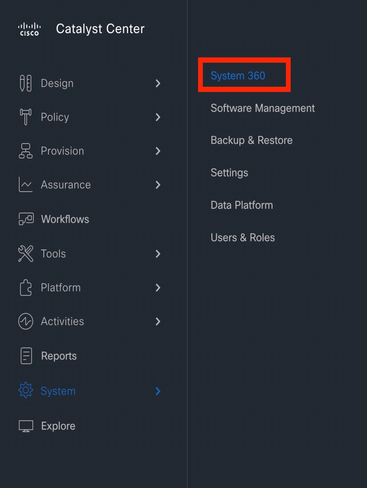
|
||||||||||
|
Step 2 |
On the System 360 dashboard, review the following displayed data metrics: Cluster
System Management
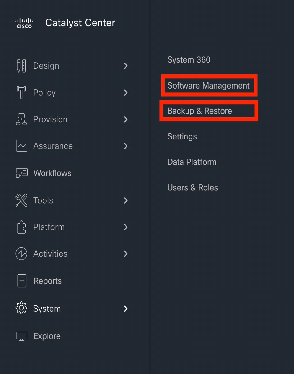
|
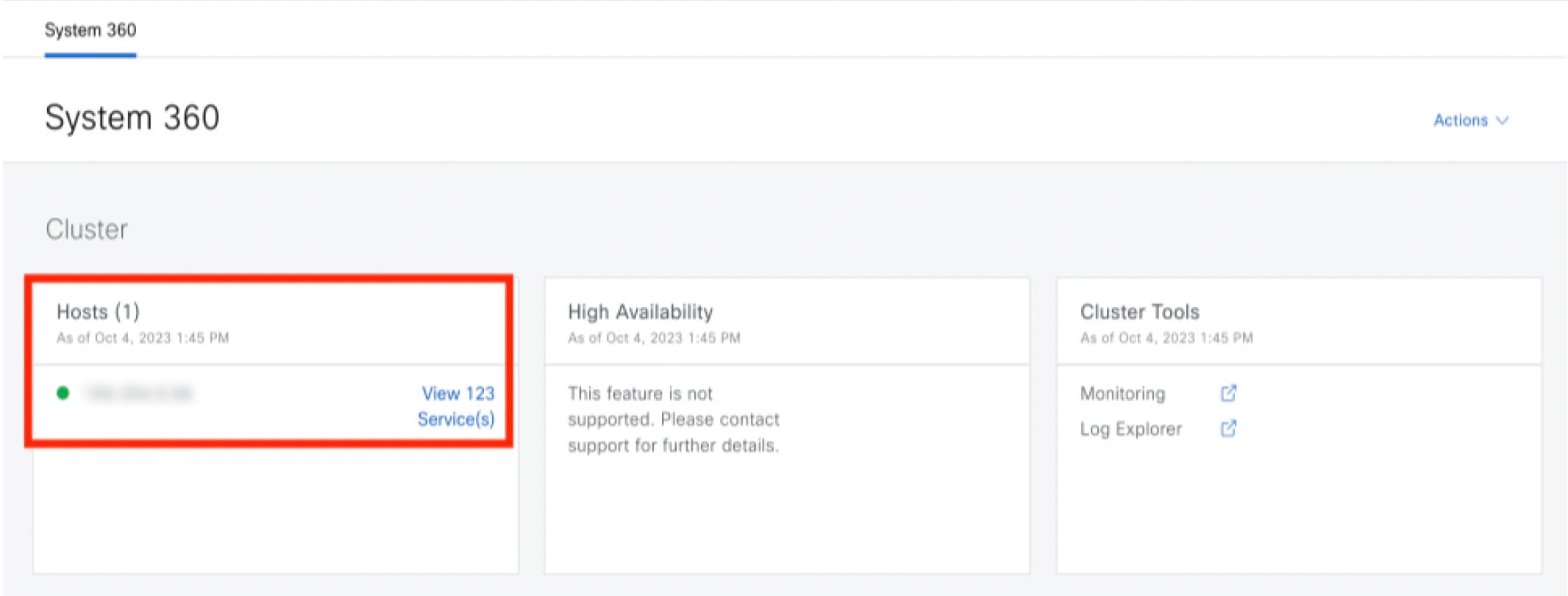
Configure Debugging Logs
To assist in troubleshooting service issues, you can change the logging level for the Catalyst Center services.
A logging level determines the amount of data that is captured in the log files. Each logging level is cumulative; that is, each level contains all the data generated by the specified level and higher levels, if any. For example, setting the logging level to Info also captures Warn and Error logs. We recommend that you adjust the logging level to assist in troubleshooting issues by capturing more data. For example, by adjusting the logging level, you can capture more data to review in a root cause analysis or RCA support file.
The default logging level for services is informational (Info). You can change the logging level from informational to a different logging level (Debug or Trace) to capture more information.
Caution |
Due to the type of information that might be disclosed, logs collected at the Debug level or higher should have restricted access. |
Note |
Log files are created and stored in a centralized location on your Catalyst Center host for display in the GUI. From this location, Catalyst Center can query and display logs in the GUI (). Logs are available to query for only the last 2 days. Logs that are older than 2 days are purged automatically from this location. |
Before you begin
Only a user with SUPER-ADMIN-ROLE permissions can perform this procedure.
Procedure
|
Step 1 |
From the top-left corner, click the menu icon and choose . 
The Debugging Logs window is displayed. |
|
Step 2 |
From the Service drop-down list, choose a service to adjust its logging level. The Service drop-down list displays the services that are currently configured and running on Catalyst Center. |
|
Step 3 |
Enter the Logger Name. This is an advanced feature that has been added to control which software components emit messages into the logging framework. Use this feature with care. Misuse of this feature can result in loss of information needed for technical support purposes. Log messages will be written only for the loggers (packages) specified here. By default, the Logger Name includes packages that start with com.cisco. You can enter additional package names as comma-separated values. Do not remove the default values unless you are explicitly directed to do so. Use * to log all packages. |
|
Step 4 |
From the Logging Level drop-down list, choose the new logging level for the service. Catalyst Center supports the following logging levels in descending order of detail:
|
|
Step 5 |
From the Time Out field, choose the time period for the logging level. Configure logging-level time periods in increments of 15 minutes up to an unlimited time period. If you specify an unlimited time period, the default level of logging should be reset each time a troubleshooting activity is completed. 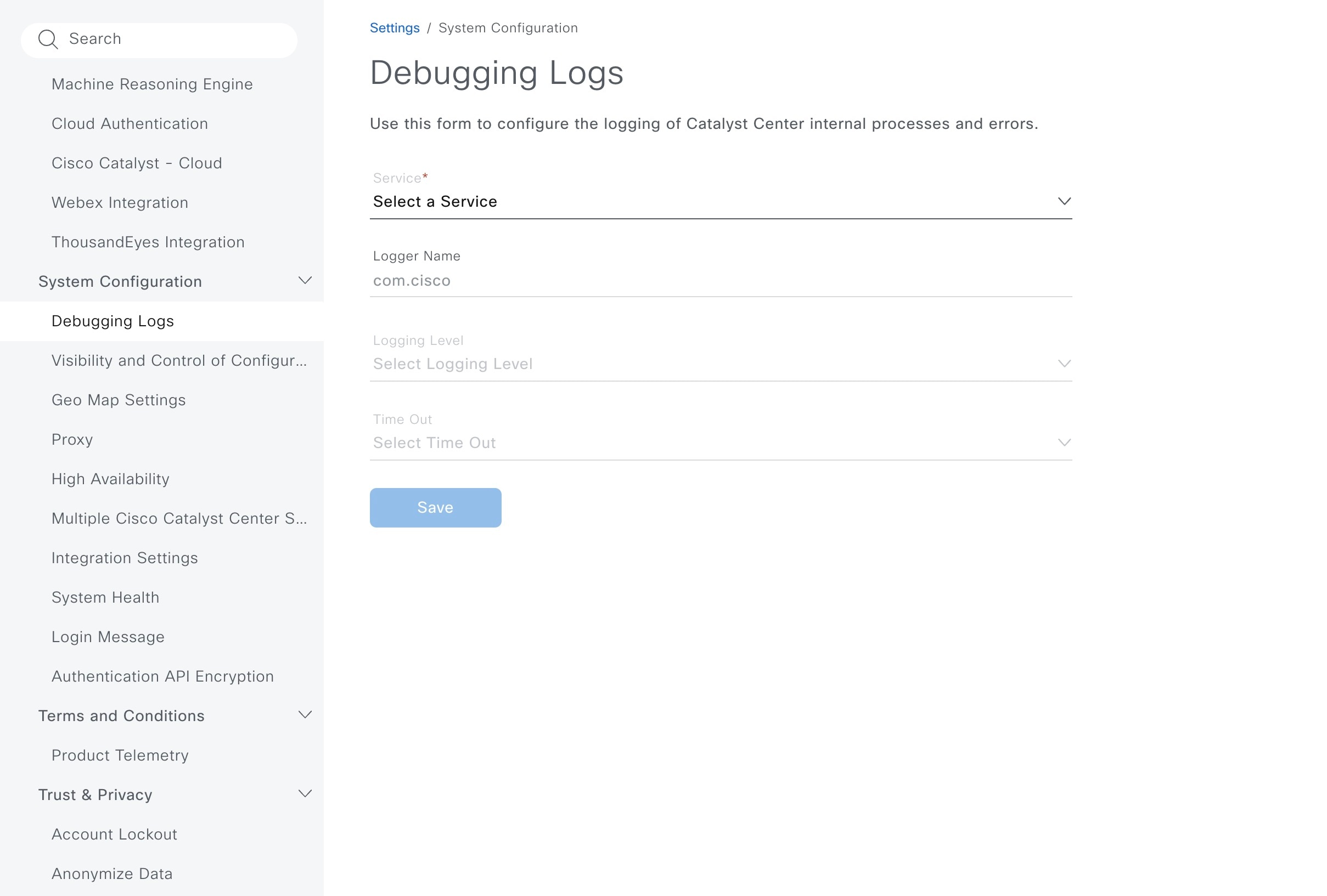
|
|
Step 6 |
Review your selection and click Save. |
View Audit Logs
Audit logs capture information about the various applications running on Catalyst Center. Audit logs also capture information about device public key infrastructure (PKI) notifications. The information in these audit logs can be used to help in troubleshooting issues, if any, involving the applications or the device CA certificates.
Audit logs also record system events that occurred, when and where they occurred, and which users initiated them. With audit logging, configuration changes to the system get logged in separate log files for auditing.
Procedure
|
Step 1 |
From the top-left corner, click the menu icon and choose . The Audit Logs window opens, where you can view logs about the current policies in your network. These policies are applied to network devices by the applications installed on Catalyst Center. 
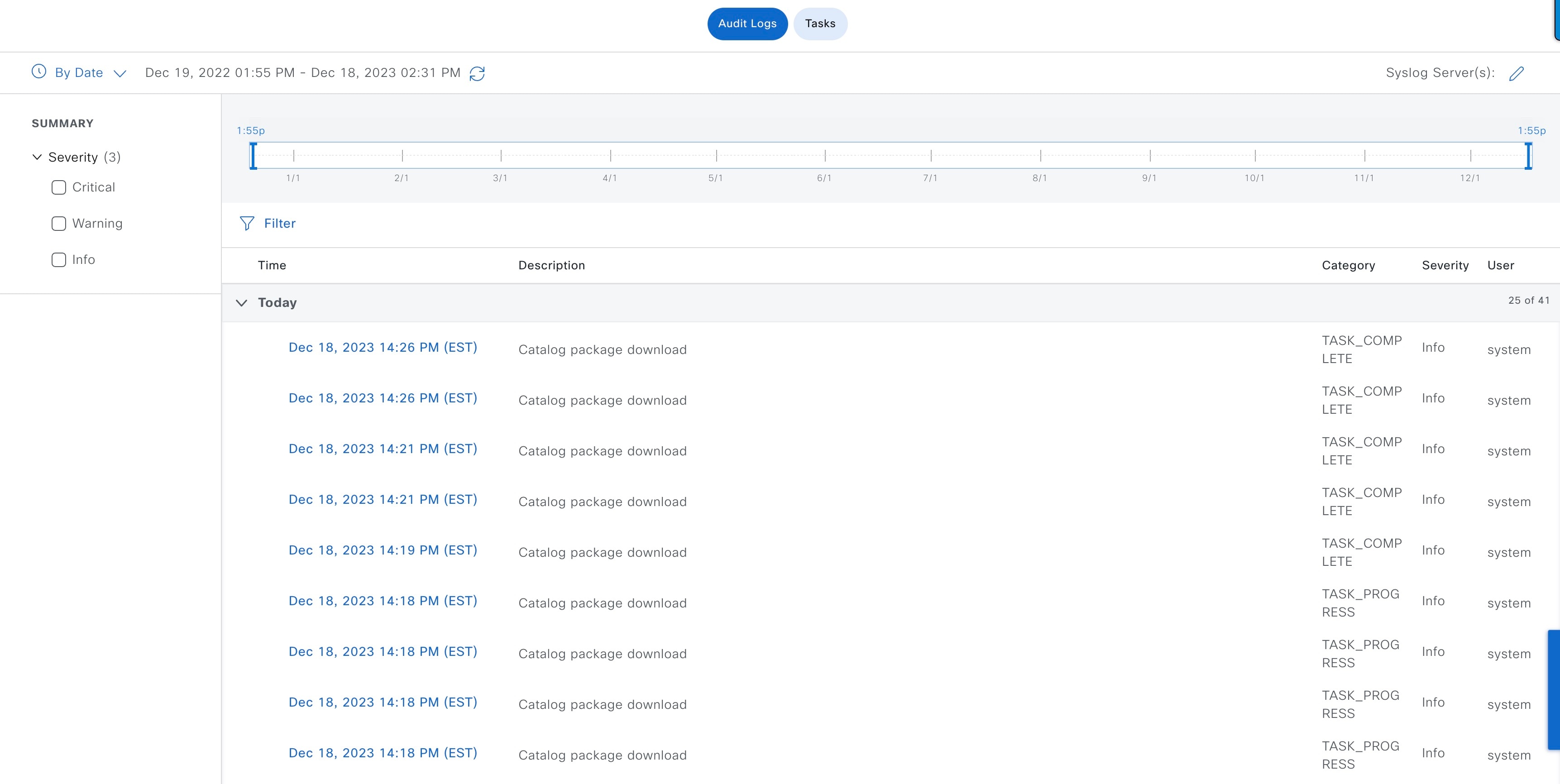
|
||
|
Step 2 |
Click the timeline slider to specify the time range of data you want displayed on the window:
|
||
|
Step 3 |
Click the arrow next to an audit log to view the corresponding child audit logs. Each audit log can be a parent to several child audit logs. By clicking the arrow, you can view a series of additional child audit logs.
|
||
|
Step 4 |
(Optional) From the list of audit logs in the left pane, click a specific audit log message. In the right pane, click . With the copied ID, you can use the API to retrieve the audit log message based on the event ID. The audit log displays the Description, User, Interface, and Destination of each policy in the right pane.
|
||
|
Step 5 |
(Optional) Click Filter to filter the log by User ID, Log ID, or Description. |
||
|
Step 6 |
Click Subscribe to subscribe to the audit log events. A list of syslog servers is displayed. |
||
|
Step 7 |
Check the syslog server check box that you want to subscribe to and click Save.
|
||
|
Step 8 |
In the right pane, use the Search field to search for specific text in the log message. |
||
|
Step 9 |
From the top-left corner, click the menu icon and choose to view the upcoming, in-progress, completed, and failed tasks (such as operating system updates or device replacements) and existing, pending-review, and failed work items. |
Export Audit Logs to Syslog Servers
Security Recommendation: We strongly encourage you to export audit logs from Catalyst Center to a remote syslog server in your network, for more secure and easier log monitoring.
You can export the audit logs from Catalyst Center to multiple syslog servers by subscribing to them.
Before you begin
Configure the syslog servers in the area.
Procedure
|
Step 1 |
From the top-left corner, click the menu icon and choose . |
|
Step 2 |
Click Subscribe. |
|
Step 3 |
Select the syslog servers that you want to subscribe to and click Save. |
|
Step 4 |
(Optional) To unsubscribe, deselect the syslog servers and click Save. |
Use APIs to View Audit Logs in Syslog Servers
With the Catalyst Center platform, you can use APIs to view audit logs in syslog servers. Using the Create Syslog Event Subscription API from the Developer Toolkit, create a syslog subscription for audit log events.
Whenever an audit log event occurs, the syslog server lists the audit log events.
Configure the Proxy
If Catalyst Center on ESXi has a proxy server configured as an intermediary between itself and the network devices that it manages, you must configure access to the proxy server.
Note |
Catalyst Center on ESXi does not support a proxy server that uses Windows New Technology LAN Manager (NTLM) authentication. |
Before you begin
Only a user with SUPER-ADMIN-ROLE permissions can perform this procedure. For more information, see the "About User Roles" topic in the Cisco Catalyst Center on ESXi Administrator Guide.
Procedure
|
Step 1 |
From the top-left corner, click the menu icon and choose . |
||
|
Step 2 |
From the System Configuration drop-down list, choose . |
||
|
Step 3 |
Enter the proxy server's URL address. |
||
|
Step 4 |
Enter the proxy server's port number.
|
||
|
Step 5 |
(Optional) If the proxy server requires authentication, click Update and enter the username and password for access to the proxy server. |
||
|
Step 6 |
Check the Validate Settings check box to have Catalyst Center on ESXi validate your proxy configuration settings when applying them. |
||
|
Step 7 |
Review your selections and click Save. To cancel your selection, click Reset. To delete an existing proxy configuration, click Delete. After configuring the proxy, you can view the configuration in the Proxy window.
|
About Restricted Shell
For added security, access to the root shell is disabled. With restricted shell, users can't access the underlying operating system and file system, which reduces operational risk.
Restricted shell is enabled for security purposes. However, if you want to access the root shell temporarily, you must contact the Cisco TAC for assistance.
If necessary, you can use the following restricted list of commands:
|
Command |
Description |
|---|---|
| cat | Concatenate and print files in restricted mode. |
| clear | Clear the terminal screen. |
| date | Display the current time in the given FORMAT or set the system date. |
| debug | Enable console debug logs. |
| df | File system information. |
| dmesg | Print or control the kernel ring buffer. |
| du | Summarize disk usage of the set of FILEs recursively for directories. |
| free | Quick summary of memory usage. |
| history | Enable shell commands history. |
| htop | Interactive process viewer. |
| ip | Print routing |
| network devices | interfaces and tunnels. |
| kubectl | Interact with Kubernetes Cluster in a restricted manner. |
| last | Show a listing of last logged in users. |
| ls | Restricted file system view chrooted to maglev Home. |
| lscpu | Print information about the CPU architecture. |
| magctl | Tool to manage a Maglev deployment. |
| maglev-config | Tool to configure a Maglev deployment. |
| manufacture_check | Tool to perform manufacturing checks. |
| netstat | Print networking information. |
| nslookup | Query Internet name servers interactively. |
| ntpq | Standard NTP query program. |
| ping | Send ICMP ECHO_REQUEST to network hosts. |
| ps | Check status of active processes in the system. |
| rca | Root cause analysis collection utilities. |
| reboot | Reboot the machine. |
| rm | Delete files in restricted mode. |
| route | Print the IP routing table. |
| runonce | Execute runonce scripts. |
| scp | Restricted secure copy. |
| sftp | Secure file transfer. |
| shutdown | Shutdown the machine. |
| ssh | OpenSSH SSH client. |
| tail | Print the last 10 lines of each FILE to standard output. |
| top | Display sorted list of system processes. |
| traceroute | Print the route packets trace to network host. |
| uname | Print system information. |
| uptime | Tell how long the system has been running. |
| vi | Text editor. |
| w | Show who is logged on and what they are doing. |
Glossary
|
Term |
Definition |
|---|---|
|
Cisco ISE |
Cisco Identity Service Engine |
|
DR |
Disaster Recovery |
|
HA |
High Availability |
|
VA |
Virtual Appliance |
Feedback and Discussions
For comments and suggestions about our guides, please join the discussion on Cisco Community.
 Feedback