Zero Trust: Network and Cloud Security Design Guide
Available Languages
Bias-Free Language
The documentation set for this product strives to use bias-free language. For the purposes of this documentation set, bias-free is defined as language that does not imply discrimination based on age, disability, gender, racial identity, ethnic identity, sexual orientation, socioeconomic status, and intersectionality. Exceptions may be present in the documentation due to language that is hardcoded in the user interfaces of the product software, language used based on RFP documentation, or language that is used by a referenced third-party product. Learn more about how Cisco is using Inclusive Language.
The Security industry is currently blessed with an abundance of Zero Trust frameworks and guidance. This guide seeks to contribute to the conversation by outlining a framework of capabilities that are necessary for the implementation of Zero Trust in any network, then provide specific design and configuration examples for achieving a strong Zero Trust posture. The Zero Trust framework used throughout this guide is built on the four Key Zero Trust Strengths shown below.
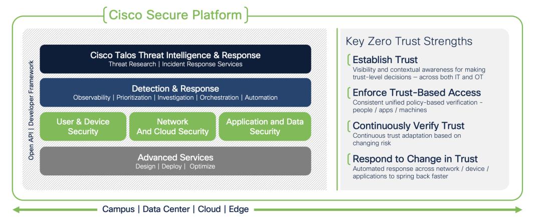
These four strengths can be mapped to broad general controls. To start, we can Establish Trust by having strong device posture and effective user authentication. We can Enforce Trust-Based Access by utilizing Role Based Access Control (RBAC) to provide Least Privilege access to users, machines, and applications. We can Continuously Verify Trust by having end-to-end network visibility and monitoring of each connection across the network, and by persistently validating the posture of connected endpoints. We can Respond to Change in Trust by building the capability to restrict or revoke access for any network connected user or device based on malicious activity or degradation in trust.
The broad capabilities in the last paragraph are a scale, just like Zero Trust is a scale—we don’t have an on/off switch for something like RBAC, but rather a layered approach that can bring us closer to the ideal that is Zero Trust. An entry-level RBAC solution could entail assigning all end users to specific Active Directory (AD) groups that cover their roles and access needs in accordance with a Least Privilege philosophy. The capabilities to achieve this entry-level RBAC solution could include requiring AD login to access the network, and then restricting access at platform or application login based on the AD group of the user. A stronger solution could validate user identity and machine posture upon login and then utilize TrustSec and Dynamic Security Group Tags (SGTs) to enforce least privilege at the network level, restricting user and group connectivity to only the needed IPs, applications, URLs, and ports necessary. Adding network access control to an RBAC solution brings several benefits that move us closer to that Zero Trust ideal: we restrict the connectivity of any potential insider threats or compromised users, limiting their capability to perform scans or other recon, footprint, or fingerprint the network; we limit the exposure of internal systems that could have known or unknown security vulnerabilities that allow unauthenticated access; we reduce the risk of an unauthorized user accessing a system with compromised break-glass (static admin credentials used for emergency access) or other local credentials. These capabilities don’t lessen the need for strong patch management or secure storage of break-glass accounts, but they do eliminate trust that can be abused and bring us closer to Zero Trust.
In the Solution Overview section of this guide, we’ll utilize the four Key Zero Trust Strengths to review scenarios like the RBAC example in the last paragraph. We’ll establish what a strong security baseline should be for each Key Strength and specify the platforms and capabilities necessary to bring each Key Strength closer to a Zero Trust ideal. The four Zero Trust Key Strengths will then be combined into an overall Zero Trust design, and extensive configuration examples will be given for implementation guidance.
Cisco Zero Trust for Network and Cloud Security design guide covers the following platforms and features:
● Cisco Catalyst 9300 Switch
o Netflow
o TrustSec
o 802.1X
o SXP
● Cisco Identity Services Engine (ISE)
o Active Directory Integration with PassiveID
o Dynamic Security Group Tag (SGT)
o pxGrid
o TrustSec
o 802.1X Authentication and Authorization
o ISE Profiling
● Cisco Secure Firewall
o Application Visibility & Control (AVC)
o Dynamic SGT
o Intrusion Protection (IPS)
o Netflow Configuration
o Network Anti-Malware
o URL Filtering
o Application Filtering
o Next Gen Firewall (NGFW) Rules
o pxGrid Integration
o Secure Malware Analytics integration
● Cisco Secure Network Analytics (formerly Stealthwatch)
o Adaptive Network Control (ANC)
o pxGrid integration
● Cisco Telemetry Broker
o Netflow Source and Destination Configuration
Out of Scope
● SD-WAN configuration is covered in our SASE guides for Meraki and Viptela
● Router configuration
● Wireless Access Point and WLC configuration
● Guest Portal
● VPN
● MacOS devices
● Windows 8 and earlier devices
● DNA Center is planned for the next revision
Zero Trust Companion Documents
While the number of Zero Trust capabilities and controls we can implement in the network and cloud is extensive, it is only one component necessary for a full approach to Zero Trust. This Zero Trust guide for Network and Cloud Security is presented as one part in a series that also covers Zero Trust capabilities for Users, Devices, and Applications. To help understand the architecture, Cisco has broken it down into three pillars:
● User and Device Security: making sure users and devices can be trusted as they access systems, regardless of location
● Network and Cloud Security: protect all network resources on-prem and in the cloud, and ensure secure access for all connecting users
● Application and Data Security: preventing unauthorized access within application environments irrespective of where they are hosted
The three guides complement each other and provide multiple integration points. For example, device management capabilities covered in the User and Device guide provide AnyConnect clients and profile configuration that are used to perform 802.1X authentication against ISE in this guide. The User and Device guide also covers remote clientless access to application resources within the network. Integration points between the guides are noted in the sections where they occur, along with hyperlinks to the relevant sections in the other guides.
Zero Trust Security Framework Map
The following table shows how common Zero Trust Frameworks map to the Cisco Zero Trust Framework.
| Cisco |
NIST Cyber Security Framework |
CISA |
Common |
| User and Device Security |
User |
Identity |
Visibility & Analytics Automation & Orchestration Governance |
| Devices |
Device |
||
| Network and Cloud Security |
Networks/Hybrid Multi-Cloud |
Network/ Environment |
|
| Application and Data Security |
Application |
Application Workload |
|
| Data |
Data |
For additional information, please refer to the Zero Trust Frameworks document.
As covered in the introduction, Cisco has created a set of four Key Zero Trust Strengths as a model for evaluating Zero Trust capabilities:
This guide uses the four Key Zero Trust Strengths as a framework to build out a solution for securing network and cloud environments using the systems and capabilities listed in the In Scope section.
Establishing Trust serves as a checkpoint when determining whether a user should be allowed access to the network, and the information gathered during this step is used to facilitate the next Key, Enforcing Trust-Based Access. As with all elements of Zero Trust, this area is a matter of degrees. Enforcing authentication at all network access points is the foundation. For the authentication itself, using static credentials to establish trust falls short of many frameworks, except for break-glass scenarios. Utilizing external authentication and an identity store like AD is an improvement. Adding multi-factor authentication (MFA) is an additional safeguard against lost or compromised external auth credentials that is increasingly seen as a required security guidance. Adding machine authentication using client certificates provides validation of the device alongside the user. Verifying the health and security status of the device adds an additional check that the device is not only known but also in an acceptable security state.
The authentication standard covered in this guide involves 802.1X authentication using an encrypted EAP-FAST connection that performs a client auth certificate check against the endpoint followed by an AD login. Based on the results of the two checks—client certificate and AD login—a Dynamic SGT is assigned to the user which is then used to enforce trust-based access, as covered in the next section.
The Cisco Zero Trust: User and Device Security Design Guide covers additional layers of Establishing Trust for endpoints, including the following:
● MFA with Duo
● Deployment of Duo Device Health Monitoring
● Deployment of certificates via Meraki Mobile Device Management (MDM)
● Deployment of AnyConnect, Network Access Manager (NAM), and associated profiles via Meraki MDM
After a user and machine have been securely authenticated to the network, the user should only be permitted to access the minimum resources needed to perform their job functions. The general principles supporting Enforce Trust-Based Access are RBAC—assigning access based on user role(s)—and Least Privilege—restricting all access that is not necessary for a given user.
It is common to enforce RBAC and Least Privilege upon login. For example, if a user attempts to access a switch, they could be prompted for a MFA login that would only succeed if valid credentials were presented and a check of the user against a Network Admins or Network Operations Center (NOC) AD group was also successful. Upon successful login, a user associated with either the Network Admins or NOC AD group could be assigned access to specific commands using TACACS.
If we add network security capabilities to the example, we can utilize TrustSec and Dynamic SGT to prevent any users who are not members of the Network Admin and NOC AD groups from even connecting to the switch for a login attempt. This additional layer of security can prevent an unauthorized and unauthenticated user from leveraging a vulnerability to do harm to a system, and mitigates the risk that compromised break-glass credentials that could be exploited for access, to give just two examples.
This guide enforces network based RBAC by assigning a Dynamic source SGT to each authenticated user that captures the user’s AD group and whether their device is trusted (passed a machine auth cert check) or untrusted (failed a machine auth cert check). The source SGT assigned by ISE is then attached to each frame generated by the user; TrustSec enforcement switches and Secure Firewall then use the source SGT to perform RBAC alongside static destination SGT assignments that are distributed via SGT Exchange Protocol (SXP). The example traffic flows used in this guide utilize the ISE TrustSec matrix to perform micro-segmentation via TrustSec access switches, denying unneeded connections between hosts connected to the same access switch. Secure Firewall performs granular Access Control and inspection for connections permitted by micro-segmentation that also pass through a firewall boundary.
For complex RBAC scenarios, such as when a single user is in multiple AD groups that all require discrete access to resources that cannot be easily represented by a single SGT, the SGT can be supplemented by AD group mappings on the firewall. This configuration has the downside of not being enforceable at the switch. The assignment of multiple SGTs to one Authorization attempt is currently a road mapped feature for ISE.
The Cisco Zero Trust: User and Device Security Design Guide covers additional layers of Enforcing Trust-Based Access:
● Authenticated remote clientless connections to internal applications with Duo Network Gateway (DNG)
The prior sections outline how a user can securely connect to the network and then be permitted a successful connection using RBAC and Least Privilege principles. However, once any successful connection is made, that connection needs to be continuously monitored both for visibility and to ensure that malicious activity does not occur in a session that passed all initial security checks. For trusted devices, the endpoint also needs to be monitored to ensure that health and security posture does not degrade.
This design utilizes Secure Network Analytics, which can perform heuristic detection for both encrypted and unencrypted flows. Switches and firewalls in the deployment are configured to export Netflow data to Cisco Telemetry Broker, which aggregates the Netflow data and forwards it to Secure Analytics for analysis. Secure Analytics will then use the flow data to detect malicious activity such as reverse shell attacks or data exfiltration and generate a corresponding alert. In addition, Secure Firewall performs Intrusion Detection and Malware Inspection on allowed connections.
The Cisco Zero Trust: User and Device Security Design Guide covers additional layers of Enforcing Trust-Based Access:
● Monitoring of endpoint posture using the Duo Health Application
The security mechanisms covered in the prior sections raise significant barriers against a potential breach or compromise of the network, but modern security best practices recommend assuming that breaches are not only possible but have already occurred. Any viable Zero Trust design requires the capability to revoke access for suspicious or malicious actors.
This design utilizes the ANC feature within Secure Analytics to assign a Quarantine SGT to suspicious or malicious hosts. ISE will receive the Quarantine designation from Secure Analytics, then leverage Change of Authorization ICoA) to force a re-authentication of the user. Upon reauthentication, ISE will match the host to an Authorization rule that denies access at the TrustSec access switch (alternatively, a Quarantine SGT can be assigned to still permit some restricted access).
Secure Firewall also inspects traffic for Intrusion events or Malware and can automatically terminate a previously allowed connection if subsequent malicious activity is detected.
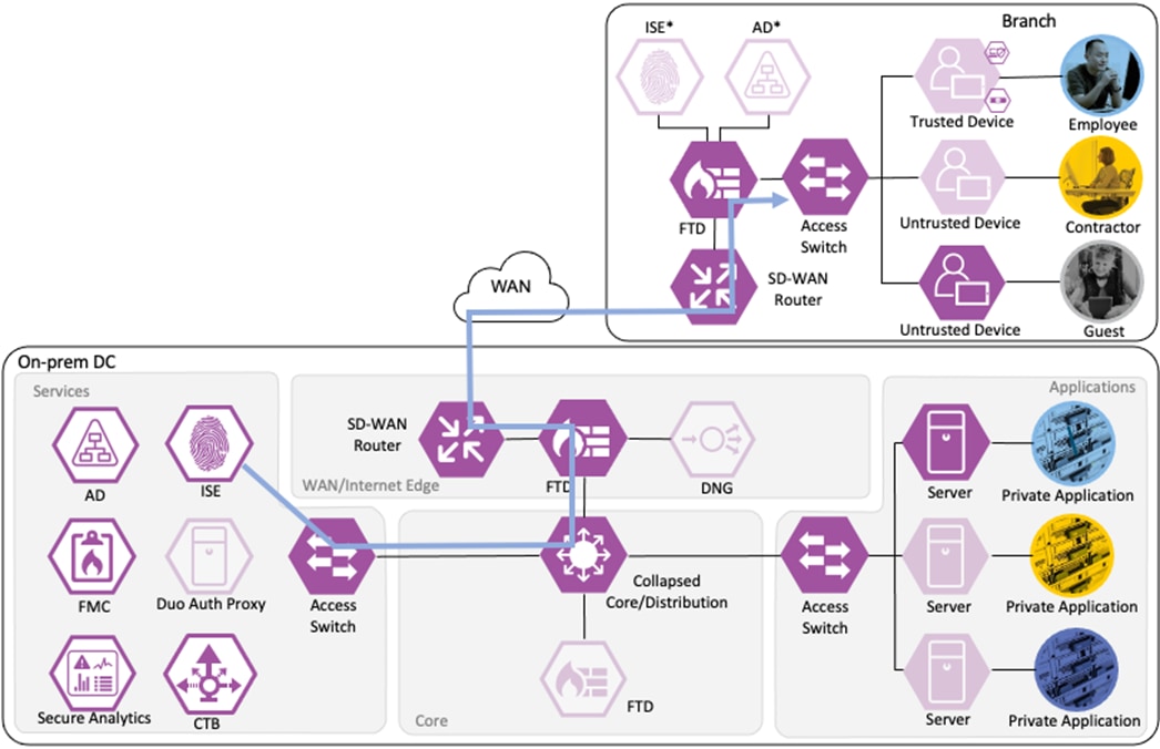
Zero Trust: Network and Cloud Security Business Flows
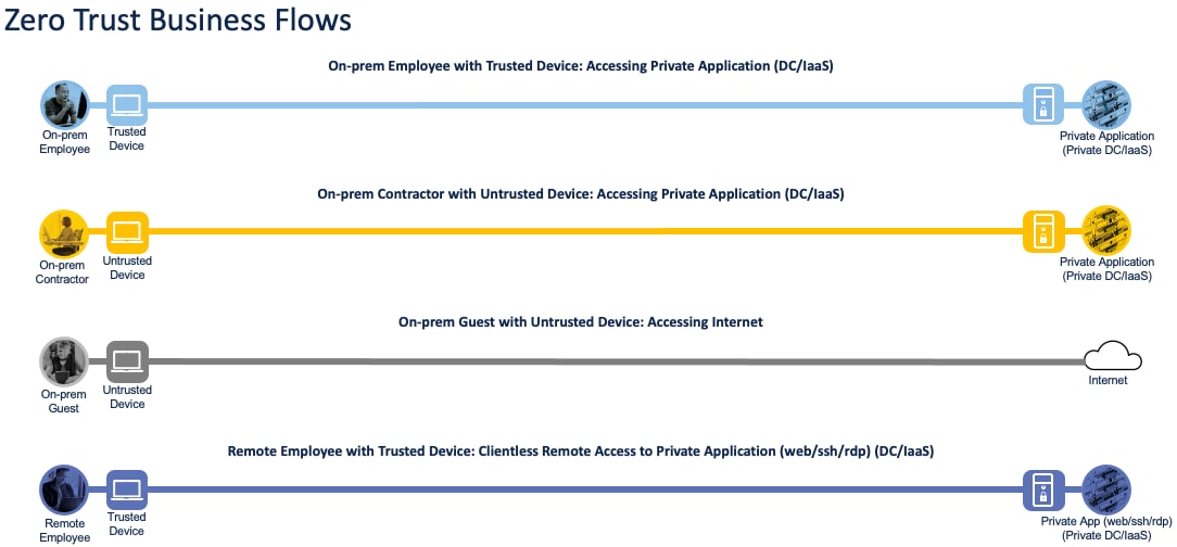
The Cisco Zero Trust Architecture Guide introduced the concept of SAFE business flows. Cisco SAFE uses the concept of business flows to simplify the analysis and identification of threats, risks, and policy requirements for effective security. This enables the selection of specific capabilities necessary to secure each business flow.
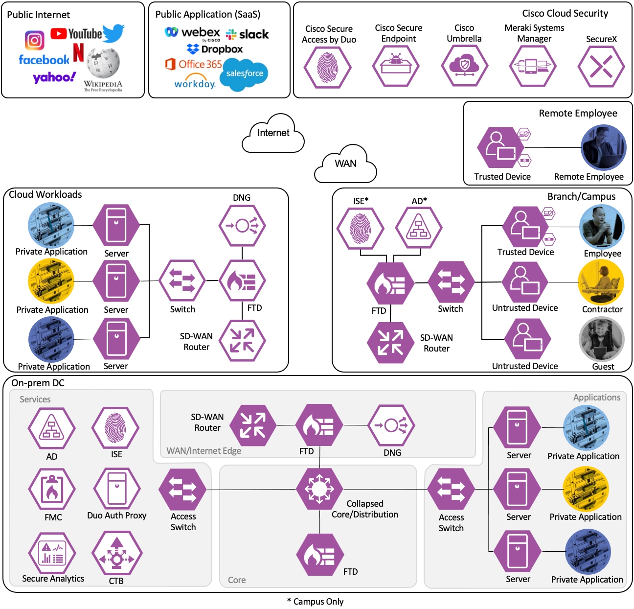
This design guide addresses the Zero Trust Network and Cloud Security aspects of the following business flows:
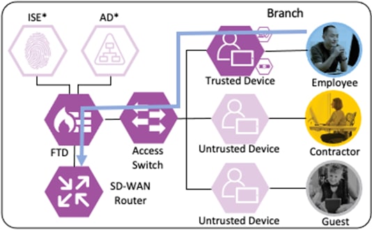
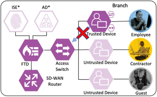
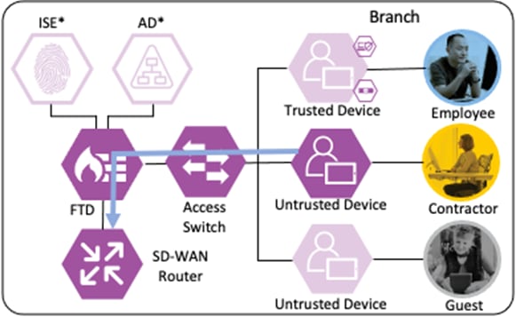
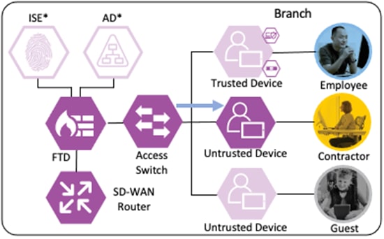
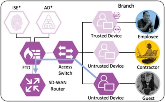
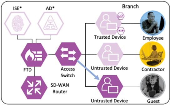
● An on-prem employee with a trusted device at a branch office accessing a private application
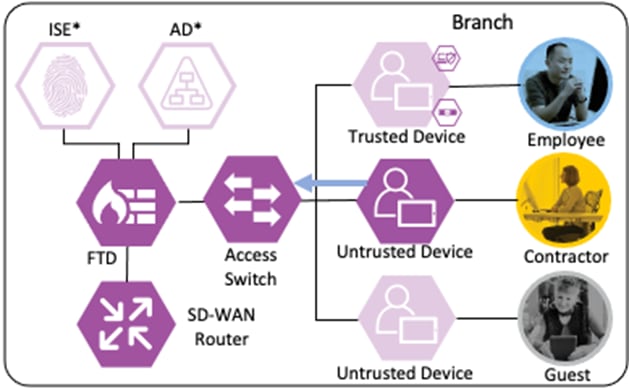
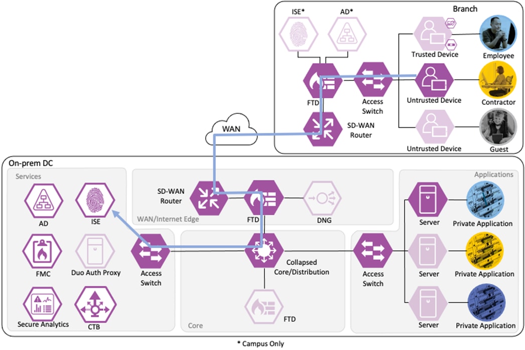
● An on-prem contractor with an untrusted device at a branch office accessing a private application
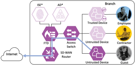
● An on-prem guest with an untrusted device at a branch office accessing a public website on the Internet
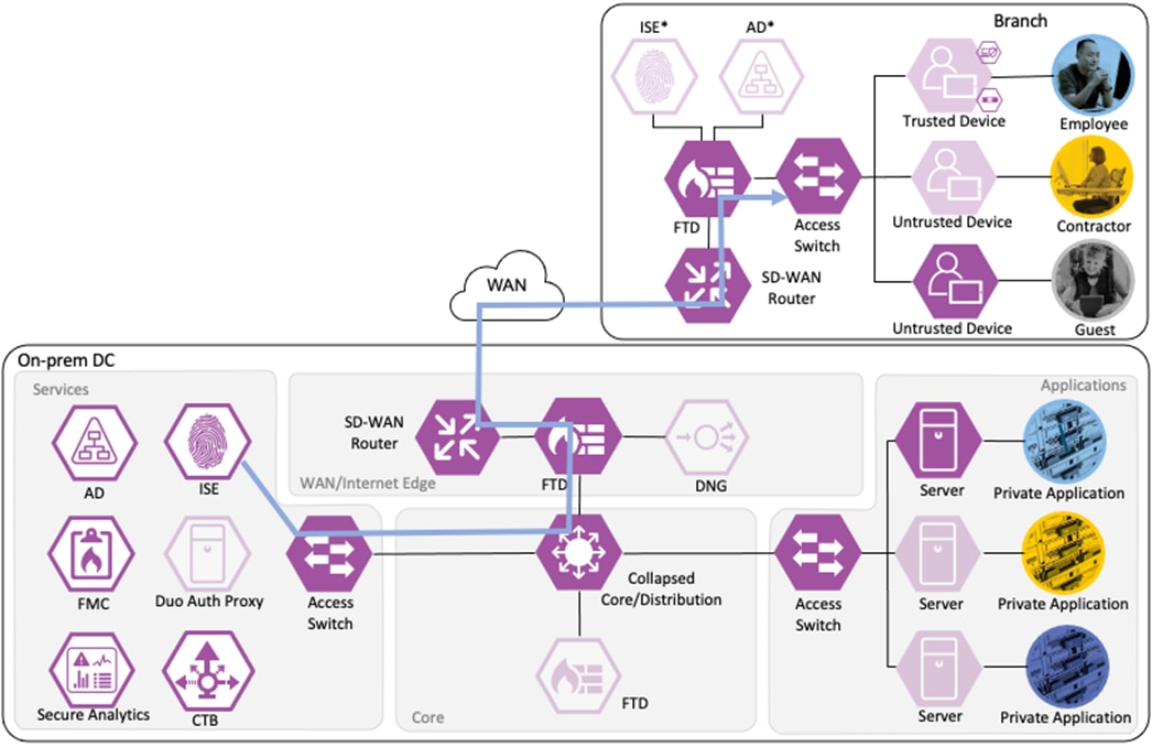
● A remote employee with a trusted device accessing a private application
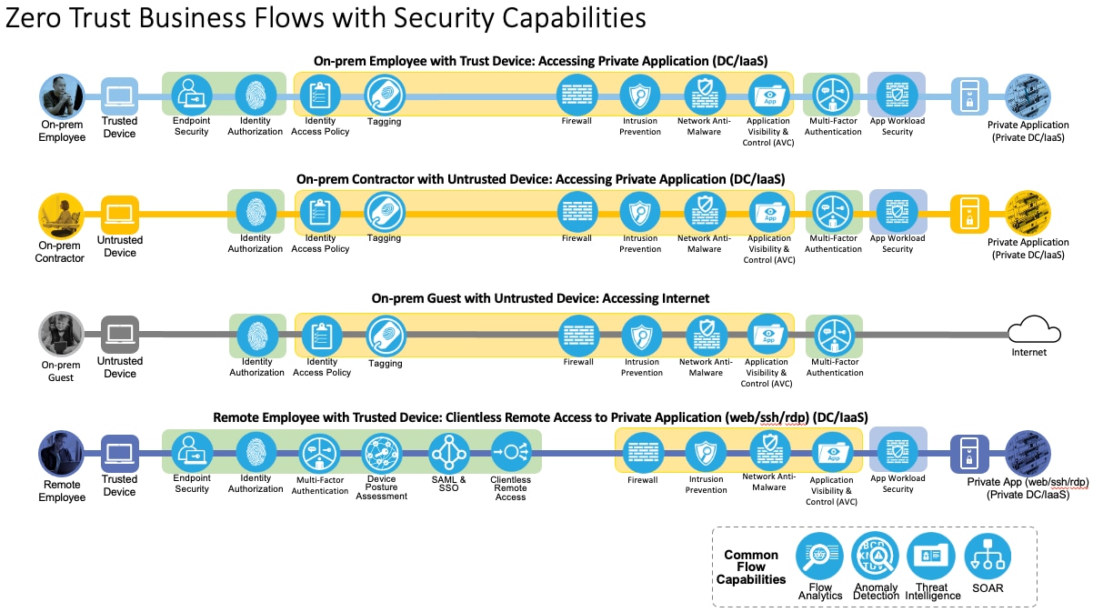
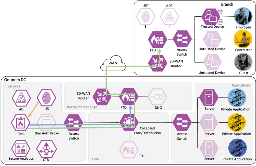
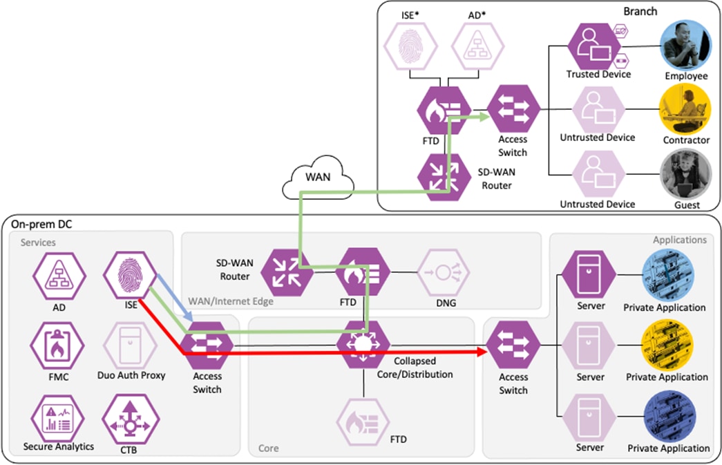
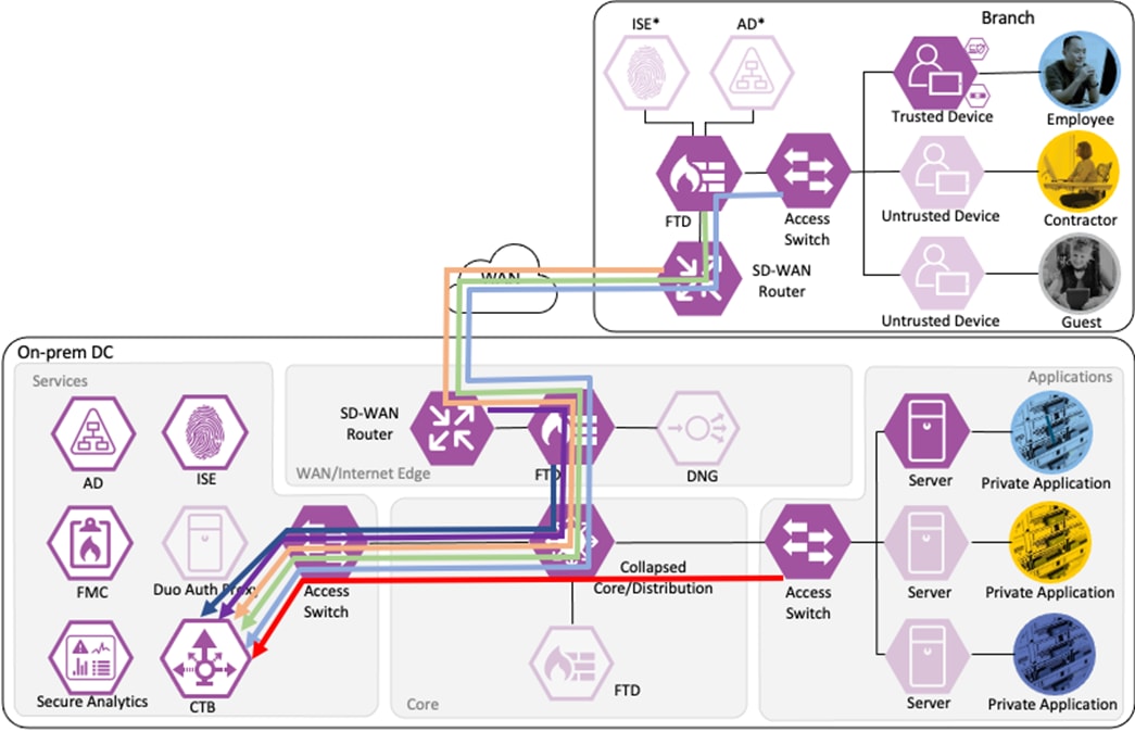
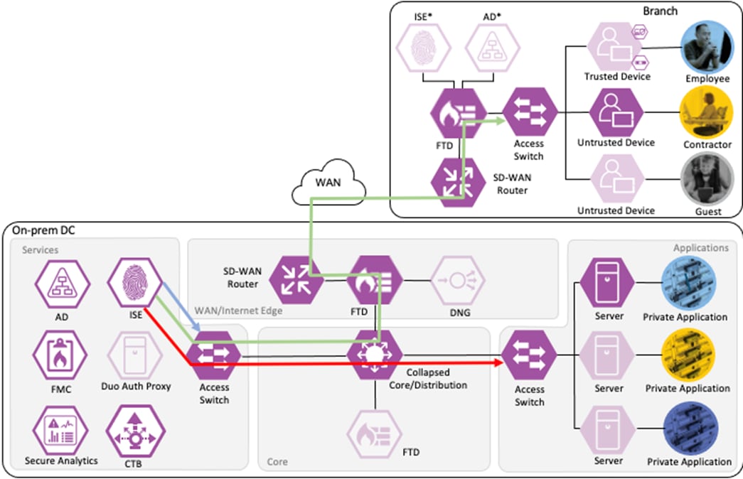
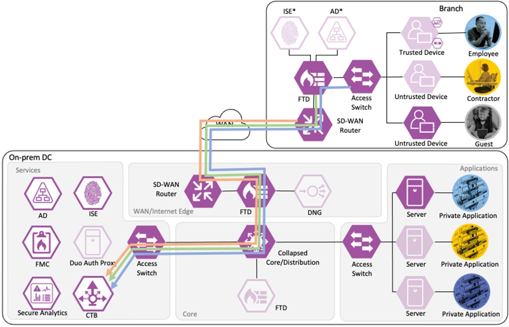
Not all business flows have the same requirements. Some use cases have a smaller attack surface and therefore require less security to be applied. Other use cases have more severe attack vectors and require additional security controls. Evaluating the business flow by analyzing the attack surfaces provides the information needed to determine and apply the correct capabilities for effective flow specific security. This process also allows for the application of capabilities to address risk and administrate policy requirements. In the following figure, the yellow security capabilities are covered within this Zero Trust for Network and Cloud Security design guide, while the green security capabilities are covered in the existing Zero Trust: User and Device Security Design Guide and the blue security capabilities in the upcoming Zero Trust for Application and Data Security design guide.
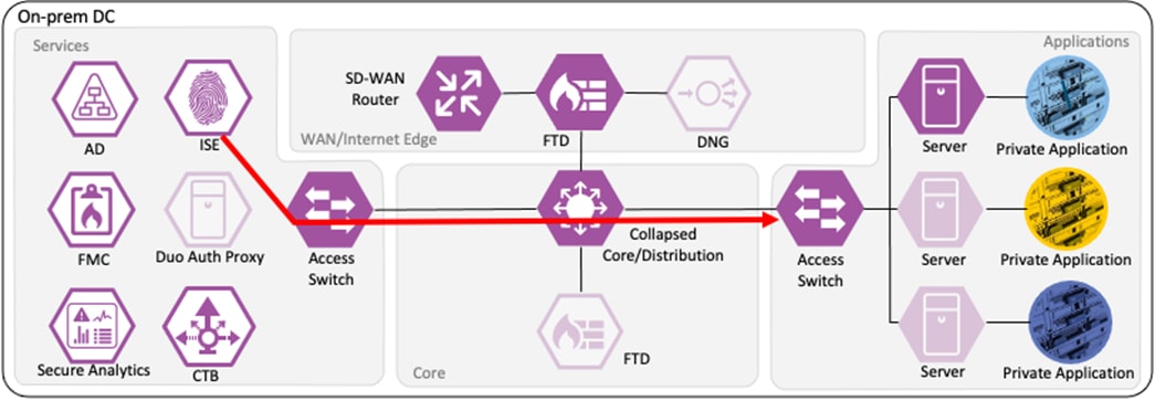
This Cisco Validated Design guide covers the following platforms for Zero Trust Network and Cloud Security:
● Cisco Catalyst 9000 Series Switch
● Cisco ISE
● Cisco Secure Firewall
● Cisco Secure Network Analytics
● Cisco Telemetry Broker
Short descriptions of each product and an outline of features deployed in the Zero Trust Network and Cloud Security Deployment section of this guide are given in the following sections. All the products have many other functionality areas that are beneficial or necessary to many customers, but only features explicitly deployed in this guide are listed in this section.
The Catalyst 9300 serves as the access switch for the deployment, functioning as both a TrustSec and 802.1X enforcement point. The switch performs an integral role in authentication, access control, monitoring, and enforcement.
The Catalyst 9300 serves as the wired 802.1X enforcement point for the network. The switch integrates with ISE to force Authentication and Authorization checks before network access is granted. If an endpoint exhibits suspicious or malicious activity, the switch can send a CoA to force the endpoint to reauthenticate, at which point the endpoint can be quarantined or receive restricted access based on a new evaluation of the device posture against the ISE AA policies.
The Catalyst 9300 generates Netflow logs based on the traffic that passes through it. The Netflow logs can then be used for end-to-end connectivity troubleshooting and threat monitoring. The Catalyst 9300 serves as one of many Netflow collection points throughout the network. The Netflow data sent by the Catalyst 9300 and other platforms is aggregated via Cisco Telemetry Broker and then fed to Secure Network Analytics for end-to-end traffic visibility and heuristic analysis.
The Catalyst 9300 receives static destination SGTs from ISE via SXP. This configuration allows SGACLs (Security Group Access Control Lists) to be distributed to the TrustSec enforcement capable switch closest to the traffic destination, allowing for scaling of SGACLs across large environments without exhausting switch resources.
The Catalyst 9300 serves as part of an end-to-end TrustSec network. The switch attaches dynamic source SGTs to all frames originating from 802.1X authenticated endpoints, which can be used by both TrustSec enforcement switches and Secure Firewall for RBAC. Micro-segmentation is accomplished through source and destination SGTs and the TrustSec Matrix in ISE. For more information on TrustSec terminology, definitions, and capabilities, please see the Cisco TrustSec Configuration Guide.
Cisco ISE is the linchpin for the deployment, serving as the backbone of AA for the network alongside Microsoft Active Directory, acting as a configuration hub and distribution point for TrustSec static SGTs and SGACLs, and functioning as an intermediary for revoking network access for end hosts utilizing pxGrid and CoA.
802.1X Authentication and Authorization
ISE receives 802.1X login attempts from access switches and evaluates them against Authentication and Authorization policies. Both machine and user logins are covered in this guide.
Active Directory Integration with PassiveID
ISE is joined to the AD domain to retrieve AD group information and to send AD login requests to Active Directory as part of the Authorization process. PassiveID is leveraged to distribute user to IP maps for AD authentications that don’t pass through ISE (such as VPN-less connections like DNG) to Secure Firewall and Secure Analytics.
ISE can send a CoA request to an access switch to force a user to reauthenticate. If the user’s posture has degraded or they have been quarantined, their access will be restricted accordingly upon reauthentication.
ISE integrates with Secure Firewall and Secure Network Analytics via pxGrid, sending destination SGTs to Secure Firewall, and user to IP maps to both devices. ISE also receives quarantine requests from Secure Analytics over pxGrid.
When users are evaluated against the ISE Authentication and Authorization policies as part of the 802.1X login process, ISE will assign a dynamic source SGT to the user based on the matched Authorization rule. ISE also serves as the configuration point for static SGT assignments for devices that do not authenticate and distributes those SGT assignments to switches and firewalls throughout the network. Finally, configuration of SGACLs is performed in ISE via the TrustSec Matrix, with SGACLs distributed through SXP.
Cisco Secure Firewall acts as an enforcer of RBAC, combining its extensive Next Gen Firewall (NGFW) capabilities with the clear user and device tracking provided by the ISE and TrustSec network. Cisco Secure Firewall is deployed alongside the Firewall Management Center (FMC). Configuration examples in this guide are performed on the FMC, which in turn pushes configurations and integration resources to firewalls throughout the network.
Application Visibility and Control
Secure Firewall performs deep packet inspection to detect the network activity of layer 7 applications. This allows for strong control of network sessions where both the port and application must match an expected value for a session to be allowed.
Secure Firewall can import Security Group lists from ISE, eliminating the need for firewall side group configuration and allowing ISE to act as a single source of truth for user and device groupings for the network. As users connect to resources in the local network and in the cloud, Secure Firewall can act on the Source and Destination SGT criteria in its Access Control Policy (ACP) to allow or block traffic based on the Source SGTs attached by the TrustSec network and the static Destination SGT mappings received from ISE via SXP.
After a session is allowed by the Secure Firewall ACP, each subsequent packet in the session can be subjected to intrusion inspection. If a session packet matches an intrusion rule set to block, the firewall will block the offending packet and any additional packets in the session will be block listed.
Secure Firewall generates Netflow data that is aggregated by the Cisco Telemetry Broker and sent to Secure Network Analytics for heuristic analysis.
After a session is allowed by the Secure Firewall ACP, each subsequent packet in the session can be subjected to malware inspection. Packets that are part of a file transfer are stored in memory and reassembled when the final file-packet reaches the firewall. If the file matches a known malicious hash or fails a Threat Grid sandbox analysis, the file can be blocked.
pxGrid serves as the communication channel with ISE. In this guide, it is used for receiving Security Groups and user to IP mappings from ISE.
SXP is used to distribute Destination SGTs to the Secure Firewall from ISE.
Secure Firewall can restrict access based on specific URLs or URL categories.
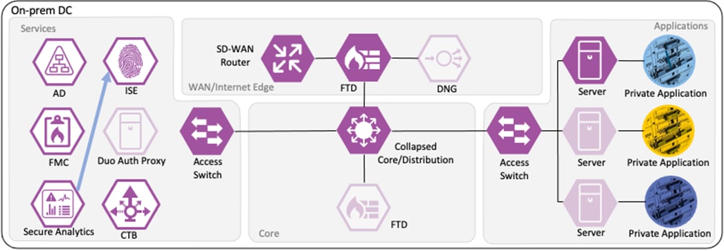
Cisco Secure Network Analytics
Cisco Secure Network Analytics performs extensive monitoring of network traffic using data collected from Netflow devices across the network. Secure Analytics performs heuristic inspection of encrypted and unencrypted flows, acting as a complement to the string based IPS detection of Secure Firewall. In this guide, Secure Network Analytics is deployed as two devices, a Flow Collector and a Management Center. Configuration examples in this guide are performed via the Management Center.
Adaptive Network Control (ANC)
Security Operations Center (SOC) analysts can respond to Secure Network Analytics alerts by issuing a quarantine action against a host using ANC. Once the quarantine action is initiated, Secure Network Analytics communicates the action to ISE over the pxGrid channel. ISE then sends a CoA request to the appropriate access switch, which forces a reauthentication of the host. When the host reauthenticates, it is matched to an ANC quarantine rule within the ISE Authorization policy. Quarantine designations can also be lifted from Secure Network Analytics.
Serves as the communication channel between ISE and Secure Network Analytics. User to IP maps are transmitted from ISE to Secure Network Analytics, and quarantine designations are transmitted from ANC to ISE.
Telemetry Broker functions as a Netflow aggregation tool. It allows for the deployment or replacement of Netflow ingestors without reconfiguring Netflow sources to point to the new destination. For example, CTB can be deployed to collect all Netflow data in a network and send it (filtered or unfiltered) to a SIEM; if a SIEM competitor were evaluated, CTB could easily be configured to send the same Netflow data to both the new SIEM and the existing SIEM, without time consuming reconfiguration of Netflow source devices. In this guide, CTB is deployed as two devices, a Node and a Manager. Configurations shown are for the Manager.
In this deployment, Telemetry Broker receives Netflow data from the Catalyst switch and Secure Firewall and dispenses the Netflow data to the Secure Analytics Flow Collector.
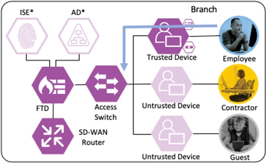
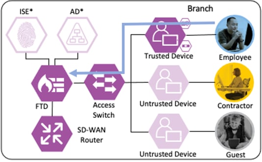
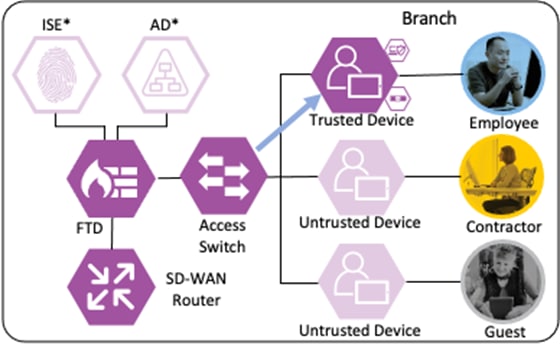
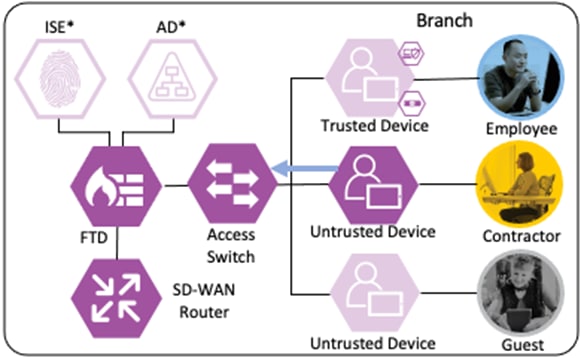
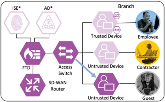
Branch – Employee, Trusted Device
The employee’s device is provisioned with AnyConnect and NAM as covered in the Zero Trust: User and Device Security Design Guide. A local client authentication certificate is provisioned to the endpoint via Active Directory (AD) Group Policy Object (GPO).
Private Application (Private DC)
Login Procedures and Network Access
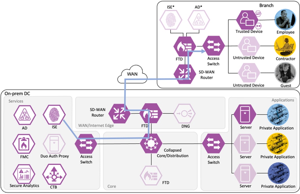
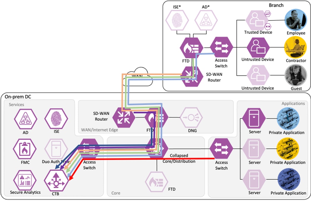
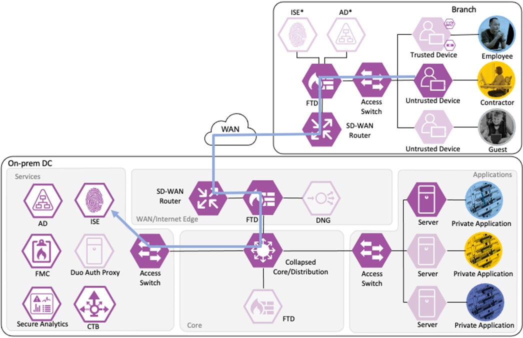
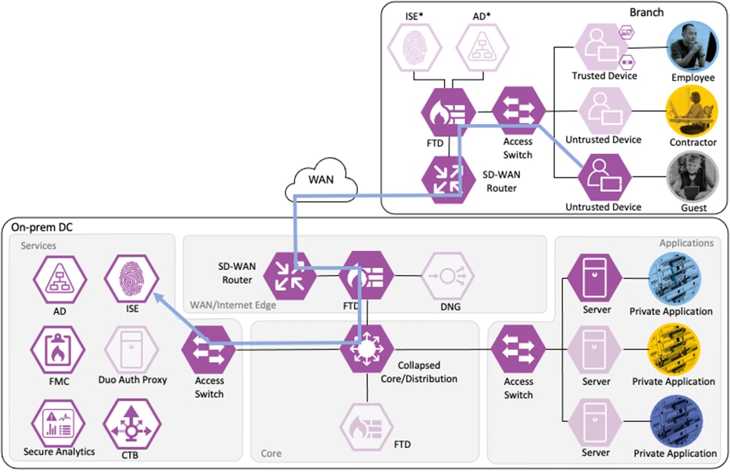
The employee connects a computer to the network via a wired ethernet port at the branch. The ethernet port is connected to a TrustSec capable access switch. Upon connection, power on, or user sign-on, the NAM installation on the endpoint attempts an 802.1X machine authentication to the switch using an encrypted EAP-FAST connection.
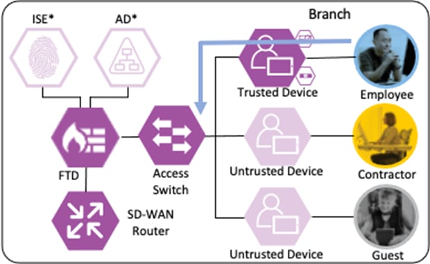
The access switch receives the 802.1X request and transmits it to ISE for processing. The connection is permitted by the Branch firewall, transmitted across the SD-WAN, and permitted again at the Datacenter boundary firewall. The Core/Distribution switches act as TrustSec Passthrough devices (not TrustSec Enforcement) and forward the connection. The Datacenter Access Switch permits the connection through its TrustSec SGACL, as configured in the TrustSec Matrix.
ISE matches the machine authentication request against its AA policies. During the AA process, the endpoint checks the EAP server certificate presented by ISE and verifies that the ISE EAP certificate matches a trusted certificate in the NAM configuration. ISE also prompts the endpoint to provide a machine auth certificate. Both certificate checks succeed, and the endpoint passes AA. ISE assigns a dynamic SGT based on the machine authentication, then returns the AA verdict to the switch along with the SGT assignment (the SGT will restrict the connectivity of the endpoint until it passes user authentication). The return connection is permitted by the Branch and Datacenter access switch SGACLs and allowed as stateful response traffic through the firewalls.
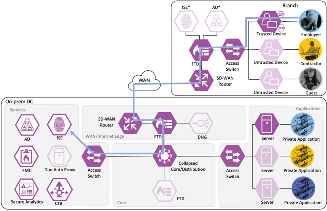
When the user attempts to access the computer, the user is presented with a prompt to enter their AD credentials. NAM initiates a new 802.1X request that uses EAP-Chaining to submit both machine and AD credentials as part of a single authorization request. The switch forwards the 802.1X request to ISE. The connection is permitted through the firewall, SD-WAN, and Datacenter access switch infrastructure as in the prior 802.1X machine authentication connection. ISE processes the 802.1X request, new checks are made against the machine and server certificate, and ISE forwards the AD credentials to a Domain Controller (DC) for validation.
The DC returns authentication success to ISE. ISE also checks what AD group(s) the user belongs to and confirms the Employee group. ISE uses the Employee group criteria in conjunction with validating the user and machine authentication to match the 802.1X attempt against an Authorization rule for Employee Trusted Device. The rule has an associated Dynamic SGT named Employee_Trusted_Device, and both the AA result and the SGT assignment are sent to the Branch access switch. Return traffic is allowed as in the prior 802.1X connection. The switch will then append the Employee_Trusted_Device source SGT to all frames originating from the end host.
Distribution of Destination SGTs and SGACLs via SXP
After logging on, the employee attempts to access an on-premises private application hosted at the datacenter. The private application is accessed via URL, with the URL resolving to a cluster of application servers with a static SGT assignment of DC_Application_Servers. This static SGT was previously distributed from ISE to the FMC via SXP. The FMC then distributed the static SGT to the firewalls across the network.
ISE has also distributed the DC_Application_Servers static SGT to the TrustSec enforcement switches throughout the network, also via SXP.
Lastly, ISE has distributed the SGACLs associated with the DC_Application_Servers to the TrustSec switch closest to the application servers (it is best practice that each switch maintains the SGACLs only for connected and closest devices to keep rule tables lean in large environments). The SGACLs are configured via the TrustSec Matrix in ISE.

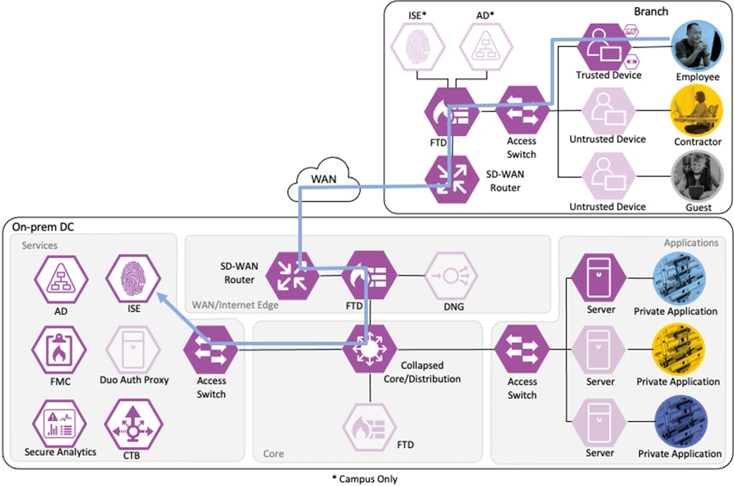
Employee to Application Server Connection
The employee initiates an HTTPS connection to the Private Application. The branch access switch receives the employee to application server connection first and appends the Employee_Trusted_Device source SGT to the frame. The branch access switch checks both the source SGT assigned to the user and the destination SGT mapped to the destination IP against its SGACL.
The access switch is not closest to the destination SGT and so has not received SGACL assignments for the destination SGT via SXP, so the access switch forwards the packet to the next hop, the Secure Firewall.
Secure Firewall evaluates the connection against its Access Control Policy using the source SGT, destination SGT, URL, application, destination port, and source and destination zones. All criteria match an allow rule permitting access to the private application. Secure Firewall allows the connection and flags the allowed packet and all subsequent packets in the connection for Intrusion and Malware inspection. Secure Firewall then sends the allowed connection to the SD-WAN router.
The SD-WAN router permits the connection and uses TrustSec Passthrough to preserve the source SGT across the IPSec tunnel between sites. The SD-WAN router routes the connection across the SD-WAN to the datacenter. (In a deployment without SD-WAN, SXP can be used to re-attach the SGT at the datacenter.)
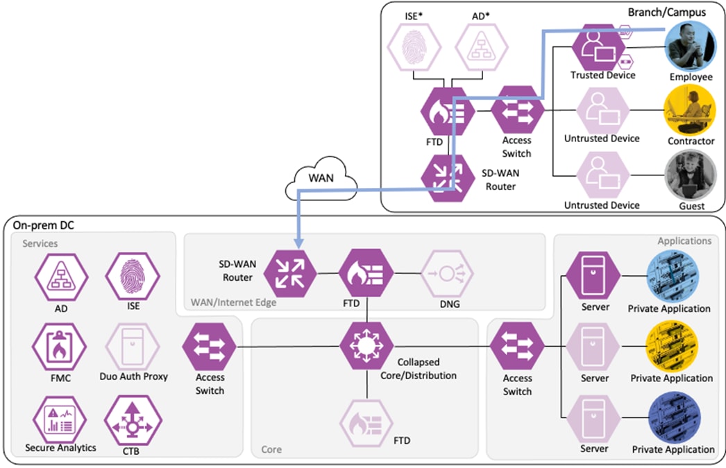
The datacenter SD-WAN router receives the connection from the branch SD-WAN router and routes it to the boundary firewall.

The boundary firewall permits the connection based on the same criteria used by the branch firewall and forwards the connection to the core switch infrastructure.
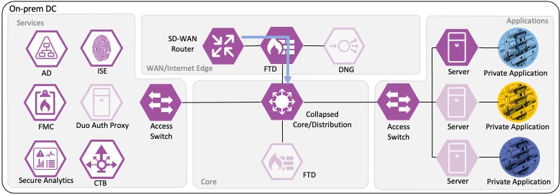
The core switch infrastructure does not enforce TrustSec Inline Tagging, but uses TrustSec passthrough to deliver the packet with attached source SGT to the access switch in the network's Applications segment.
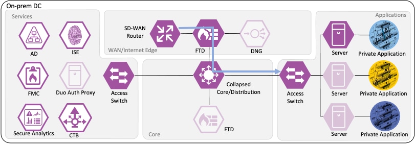
The access switch evaluates the source SGT and destination SGT against its SGACL. Because the access switch in the Applications segment of the network is the closest TrustSec device to the application servers, it has received SGACL rules for the destination SGT. The SGACL permits the connection, and the packet successfully reaches its destination of the private application server.

Netflow Collection
The routers, firewalls, and switches all generate a Netflow record of the connection and send Netflow data to the datacenter CTB node.
Note: The granularity of Netflow data can be a question of design. Collecting at every point delivers more point-to-point visibility for platforms like Secure Analytics. However, only collecting Netflow closest to the source and destination reduces log storage requirements.
CTB aggregates the Netflow data and sends it to a Secure Network Analytics Flow Collector for analysis and session tracking.

Secure Network Analytics collects the flow data and generates flow events.
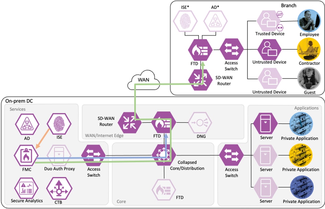
Monitoring of Allowed Connections
As additional packets are sent over the allowed connection, the data for each packet is added to end of session logging for Secure Firewall and sent to Secure Analytics through additional Netflow logs. Each additional packet is also subjected to Intrusion Protection and Malware blocking, depending on protocol. If an intrusion event or malware is detected by the Secure Firewall, the connection is terminated, and an event is generated.
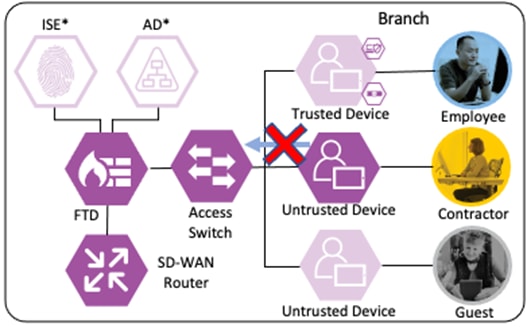
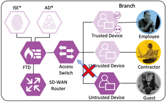
If Secure Network Analytics detects malicious activity over the session, it will generate an alert based on the activity observed. If the malicious activity warrants a response action, the SOC can use the ANC feature of Secure Network Analytics to send a quarantine request to ISE.

ISE receives the quarantine request and sends a CoA request to the access switch of the target host.
The switch performs the CoA against the host, forcing the host to reauthenticate via 802.1X.
When the host reauthenticates, the ANC assignment matches the reauthentication attempt against a Quarantine rule in the ISE Authorization policy, with a result of Deny Access.
The switch blocks all network access for the host until the quarantine is lifted and the host completes a successful 802.1X user authentication.
Additional security for the user to private application is provided in the companion Zero Trust guides. For Duo MFA for the user to application connection, please see the Zero Trust: User and Device Security Design Guide. For security specific to the application, please see the upcoming Zero Trust: Application Security Design Guide.
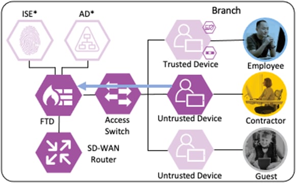
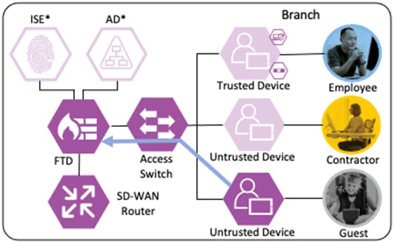
Branch – Contractor, Untrusted Device
Depending on the organization's security policy, the contractor’s device may or may not be provisioned with all of the same applications as an employee. In this example, no applications are installed on the contractor’s device, and it is considered untrusted. However, the device has been joined to the AD domain and configured for 802.1X. While the Contractor with Untrusted Device has different application access than the Employee with Trusted Device, the methodology for validating the user and device and then granting access to a permitted application is the same as in the prior section.
Private Application (Private DC)
Login Procedures and Network Access
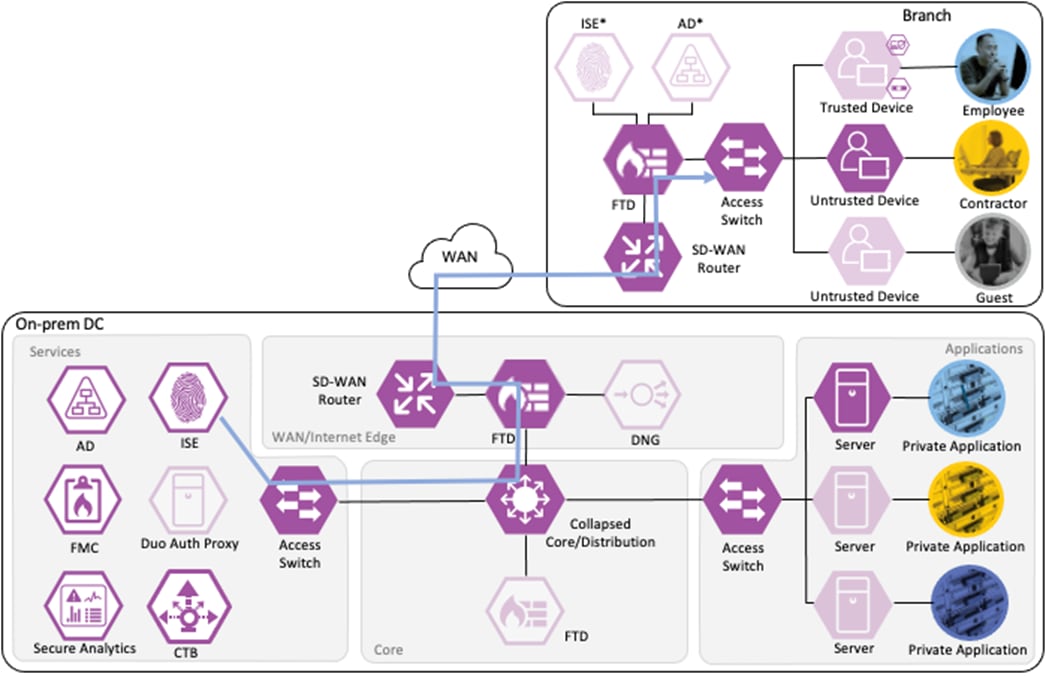
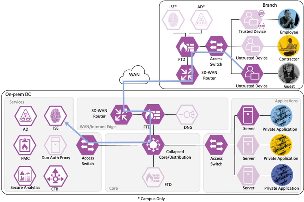
The contractor connects a computer to the network via a wired ethernet port at the branch. The ethernet port is connected to a TrustSec capable access switch. When the user attempts to access the computer, the user is presented with a prompt to enter their AD credentials. The AD credentials are sent to the switch as part of an 802.1X request.
The switch receives the 802.1X request and transmits it to ISE for processing. The connection is permitted by the Branch firewall, transmitted across the SD-WAN, and permitted again at the Datacenter boundary firewall. The Core/Distribution switches act as TrustSec Passthrough devices (not TrustSec Enforcement) and forward the connection. The Datacenter Access Switch permits the connection through its TrustSec SGACL, as configured in the TrustSec Matrix.
ISE processes the 802.1X request and forwards the AD credentials to a Domain Controller for validation.

The Domain Controller returns an auth success to ISE. ISE also checks what AD group(s) the user belongs to and confirms the Contractor group. While the user has successfully authenticated against AD, they have not presented a certificate for machine authentication. ISE uses the Contractor group criteria, the AD auth success, and the machine authentication failure to match the 802.1X attempt against an Authorization rule for Contractor Untrusted Device. The rule has an associated Dynamic SGT named Contractor_Untrusted_Device, and both the AA result and the SGT assignment are sent to the Branch access switch. The return connection is permitted by the Branch and Datacenter access switch SGACLs and allowed statefully as response traffic through the firewalls. The switch will then append the Contractor_Untrusted_Device source SGT to all frames originating from the end host.
Distribution of Destination SGTs and SGACLs via SXP
After logging on, the contractor attempts to access an on-premises private application hosted at the datacenter. The private application is accessed via URL, with the URL resolving to a cluster of application servers with a static SGT assignment of DC_Application_Servers. This static SGT was previously distributed from ISE to the FMC via SXP. The FMC then distributed the static SGT to the firewalls across the network.
ISE has also distributed the DC_Application_Servers static SGT to the TrustSec enforcement switches throughout the network, also via SXP.
Lastly, ISE has distributed the SGACLs associated with the DC_Application_Servers to the TrustSec switch closest to the application servers (it is best practice that each switch maintains the SGACLs only for connected and closest devices to keep rule tables lean in large environments). The SGACLs are configured via the TrustSec Matrix in ISE.
Contractor to Application Server Connection
The contractor initiates an HTTPS connection to the Private Application. The branch access switch receives the contractor to application server connection first and appends the Contractor_Untrusted_Device source SGT to the frame. The branch access switch checks both the source SGT assigned to the user and the destination SGT mapped to the destination IP against its SGACL.
The access switch is not closest to the destination SGT and so has not received SGACL assignments for the destination SGT via SXP, so the access switch forwards the packet to the next hop, the Secure Firewall.
Secure Firewall evaluates the connection against its Access Control Policy using the source SGT, destination SGT, URL, application, destination port, and source and destination zones. All criteria match an allow rule permitting access to the private application. Secure Firewall allows the connection and flags the allowed packet and all subsequent packets in the connection for Intrusion and Malware inspection. Secure Firewall then sends the allowed connection to the SD-WAN router.
The SD-WAN router permits the connection and uses TrustSec Passthrough to preserve the source SGT across the IPSec tunnel between sites. The SD-WAN router routes the connection across the SD-WAN to the datacenter.

The datacenter SD-WAN router receives the connection from the branch SD-WAN router and routes it to the boundary firewall.
The boundary firewall permits the connection based on the same criteria used by the branch firewall and forwards the connection to the core switch infrastructure.
The core switch infrastructure does not enforce TrustSec Inline Tagging, but uses TrustSec passthrough to deliver the packet with attached source SGT to the access switch in the network's Applications segment.
The access switch evaluates the source SGT and destination SGT against its SGACL. Because the access switch in the Applications segment of the network is the closest TrustSec device to the application servers, it has received SGACL rules for the destination SGT. The SGACL permits the connection, and the packet successfully reaches its destination of the private application server.
Netflow Collection
The routers, firewalls, and switches all generate a Netflow record of the connection and send Netflow data to the datacenter CTB node.
Note: The granularity of Netflow data can be a question of design. Collecting at every point delivers more point-to-point visibility for platforms like Secure Analytics. However, only collecting Netflow closest to the source and destination reduces log storage requirements.
CTB aggregates the Netflow data and sends it to a Secure Network Analytics Flow Collector for analysis and session tracking.

Secure Network Analytics collects the flow data and generates flow events.
Monitoring of Allowed Connections
As additional packets are sent over the allowed connection, the data for each packet is added to end of session logging for Secure Firewall and sent to Secure Analytics through additional Netflow logs. Each additional packet is also subjected to Intrusion Protection and Malware blocking, depending on protocol. If an intrusion event or malware is detected by the Secure Firewall, the connection is terminated, and an event is generated.
If Secure Network Analytics detects malicious activity over the session, it will generate an alert based on the activity observed. If the malicious activity warrants a response action, the SOC can use the ANC feature of Secure Network Analytics to send a quarantine request to ISE.
ISE receives the quarantine request and sends a CoA request to the access switch of the target host.
The switch performs the CoA against the host, forcing the host to re-authenticate via 802.1X.
When the host reauthenticates, the ANC assignment matches the reauthentication attempt against a Quarantine rule in the ISE Authorization policy, with a result of Deny Access.
The switch blocks all network access for the host until the quarantine is lifted and the host completes a successful 802.1X user authentication.
Additional security for the user to private application is provided in the companion Zero Trust guides. For Duo MFA for the user to application connection, please see the Zero Trust: User and Device Security Design Guide. For security specific to the application, please see the upcoming Zero Trust: Application Security Design Guide.
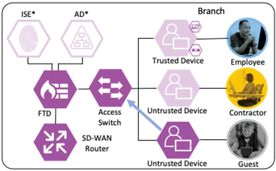
The guest user has a BYOD with no organization-controlled software or trusted certificates.
Login Procedures and Network Access
The guest user attempts a connection to an open Guest WI-FI SSID. The wireless access point (WAP) that hosts the SSID forwards the connection request to a Wireless LAN Controller (WLC).

The WLC in turn forwards the connection request to ISE.
ISE authenticates the connection against its AA policies, returning a URL redirect and URL redirect ACL to the WLC. The guest user receives the URL redirect, which sends them to the ISE guest access portal. The guest user performs the Register for Guest Access action and creates an account, after which they are assigned a username and password, then prompted to log in. After the guest successfully logs in to the ISE guest portal, ISE sends a CoA to the WLC.
The WLC responds to the CoA by prompting the user to re-authenticate using their new credentials.
The user reauthentication is sent to ISE.
ISE matches the access request against an Authorization rule that assigns the Guest SGT and returns the access result and the SGT to the WLC.
The WLC will then append the Guest SGT to each frame generated by the guest user.
Guest to Internet Connection
The guest user then attempts to access the internet. The destination public IP in the connection matches the Unknown static SGT (best practice for SGACL configuration has been followed with all internal subnets mapped to SGACLs, with the Unknown SGT used as a catch all for IP spaces outside the network). The WLC permits the connection as traffic to the Unknown SGT is not blocked by SGACL.
The connection is sent to the Secure Firewall, where it is evaluated against the Access Control Policy.
Secure Firewall evaluates the connection using the source SGT, destination SGT, and source and destination zones. All criteria match an allow rule permitting the Guest SGT to connect to the Unknown SGT from a guest wireless zone to an outside zone. Secure Firewall allows the connection and flags the allowed packet and all subsequent packets in the connection for Intrusion inspection to mitigate the risk of outbound attacks launched by a guest to an internet target from the company public IP space.
The SD-WAN router receives the connection from the firewall outside zone and routes the connection to the internet.
The switch, firewall, and router all generate a Netflow record of the packet and send the Netflow to a CTB node at the datacenter over the SD-WAN connection.
CTB aggregates the Netflow records and sends it to a Secure Network Analytics Flow Collector for analysis and session tracking.

Secure Network Analytics collects the flow data and generates flow events.
Monitoring of Allowed Connections
As additional packets are sent over the allowed connection, the data for each packet is added to end of session logging for Secure Firewall and sent to Secure Analytics through additional Netflow logs. Each additional packet is also subjected to Intrusion inspection, depending on protocol. If an Intrusion event is detected by the Secure Firewall, the connection is terminated, and an event is generated.
If Secure Network Analytics detects malicious activity over the session, it will generate an alert based on the activity observed. If the malicious activity warrants a response action, the SOC can use the ANC feature of Secure Network Analytics to quarantine the host through its integration with ISE.

After the SOC initiates the ANC quarantine action, Secure Analytics will transmit the request to ISE. ISE will then force a CoA request for the associated host.
The WLC performs the CoA against the host, forcing the host to re-authenticate.
When the host reauthenticates, the ANC assignment matches the reauthentication attempt to a Quarantine rule in the ISE Authorization policy, with a result of Deny Access.
The switch blocks all network access for the host until the quarantine is lifted and the host completes a successful authentication.
Additional Guides and Resources
The Firewall Access Control and TrustSec SGACL configuration sections of this guide focus on the Employee, Contractor, and Guest connections covered in the prior Zero Trust Design section. However, additional connections must be allowed for the different integrations covered in the Deployment section, depending on network topology. For a list of ports required for RADIUS (used in this guide for 802.1X), pxGrid, CoA, SXP, PassiveID (the AD Agent is deployed in this guide), and TrustSec, please see the Cisco ISE Ports Reference guide. ISE will initiate outbound LDAP, SMB, and KDC connections to AD, which are also covered in the ISE Ports Reference guide. Lastly, Netflow connections between multiple platforms are covered in the Deployment section; the default Netflow port is UDP 2055.
This guide covers the handling of Guest connections through the ISE AA policies, the TrustSec Matrix, and Secure Firewall rules utilizing Dynamic and Static SGTs. For comprehensive guidance on setup and configuration of a Guest Wireless deployment, please see the ISE Guest Access Prescriptive Deployment Guide.
The Zero Trust Network and Cloud Security Deployment section covers many different product configurations, and it may be helpful for some users to review dependencies between the different configuration topics. A high level overview of how the different configurations support and integrate with each other is provided below.
Integrate ISE with Active Directory
● AD user groups are utilized in the configuration of Authorization rules in the Configure ISE Policy Sets section
● During 802.1X logins (the Configure 802.1X section), ISE uses AD for machine and user lookups and AD credential validation
● The pxGrid Configuration and Integration section establishes Secure Firewall and Secure Network Analytics as pxGrid Subscribers, which can receive PassiveID user to IP maps from ISE
pxGrid Configuration and Integration
● User to IP mappings are transmitted from ISE to Secure Firewall and Secure Network Analytics. These user to IP maps come directly from ISE for 802.1X logins and from the PassiveID for AD logins that do not go through ISE (the VPN-less connection through the DNG)
● Secure Network Analytics uses the Adaptive Network Control Configuration to send quarantine requests to ISE over the pxGrid channel
● The Configure ISE Security Groups and Static Mapping section covers creation of new Security Groups which are sent to Secure Firewall via pxGrid. The Security Groups are used in Secure Firewall policy creation in the Secure Firewall Access Control with Dynamic SGT section
● pxGrid Configuration and Integration can be found in the SAFE Certificate Management Design Guide.
Adaptive Network Control Configuration
● Secure Network Analytics will use the pxGrid channel created in the pxGrid Configuration and Integration section to send host quarantine designations to ISE via ANC
● The Netflow logs generated and transmitted to Secure Network Analytics in the Configure Netflow section form the basis for the security events used to make ANC quarantine designations
● The Configure ISE Security Groups and Static Mapping section sets the Security Groups that will be used for TrustSec SGTs
● The Configure TrustSec SGACLs section sets access control that is enforced by TrustSec access switches
● Source SGTs are assigned on 802.1X login (Configure 802.1X) via Authorization rules from the Configure ISE Policy Sets section. The source SGTs are then attached to host frames by TrustSec switches and used for TrustSec enforcement
● ISE uses SXP to assign destination SGTs to the TrustSec switch closest to the destination host. The TrustSec switches then retrieve the SGACLs (Configure TrustSec SGACLs) that apply to the destination SGTs
● ISE uses SXP to distribute the static IP to Security Group mappings to the FMC, which are necessary for the Secure Firewall Access Control with Dynamic SGT section
● 802.1X logins require ISE to perform user and machine checks against AD (Integrate ISE with Active Directory)
● 802.1X logins are evaluated against AA rules from the Configure ISE Policy Sets section
● ISE assigns SGTs upon 802.1X Authorization that are drawn from Security Groups in the Configure ISE Security Groups and Static Mapping section
Configure ISE Security Groups and Static Mapping
● Security Groups are used to assign SGTs upon 802.1X login
● Security Groups are distributed to firewalls and TrustSec switches via the Configure SXP section
● Security Groups are used to build SGACLs in the Configure TrustSec SGACLs section
● Security Groups are used for the SGT assignments in the Configure ISE Policy Sets section
● Security Groups are used as rule criteria in the Secure Firewall Access Control with Dynamic SGT section
● SGACLs are used by TrustSec switches (Configure TrustSec) to enforce network-based access control
● SGACLs are created using the groups from the Configure ISE Security Groups and Static Mapping section
ISE Authentication and Authorization Policy Preparation
● This section sets certificates and configurations that are necessary for 802.1X login and for the Configure ISE Policy Sets section
● ISE policies use groups from the Configure ISE Security Groups and Static Mapping section
● 802.1X logins are evaluated against the Authentication and Authorization policies configured in this section
● The Authorization policy configured in this section assigns SGTs that are used by the switches in the Configure TrustSec section and by the Secure Firewall Access Control with Dynamic SGT section
Secure Firewall Access Control with Dynamic SGT
● This section uses Security Groups from the Configure ISE Security Groups and Static Mapping section
● This section receives static IP to Security Group maps from ISE via the Configure SXP section that are used for destination SGTs in the Access Control policy
Zero Trust: Network and Cloud Security Deployment
This deployment section can be followed linearly to accomplish the capabilities outlined in the Zero Trust Design section. Required platforms and platform capabilities are listed in the Product Overview section. An outline of how the configuration in the following subsections interact with each other is included in the preceding Overview of Integrations section.
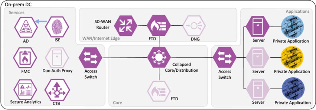
Integrate ISE with Active Directory
ISE leverages Active Directory (AD) for multiple methods of authentication, including the 802.1X configuration in this guide. Groups imported from AD will also be used later in the AA rules for 802.1X. AD is also used to retrieve user to IP mappings for PassiveID.
Step 1. Before integrating AD with ISE, confirm that you have admin access available for both AD and ISE and then perform the following checks.
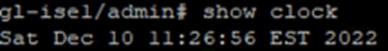
Step 2. Verify the clocks of the AD server and ISE are synced, preferably via a common NTP server. The time for an ISE node can be verified with the show clock command:
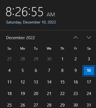
Step 3. On the AD server, click the time and date on the right side of the task bar to see the current time in seconds.
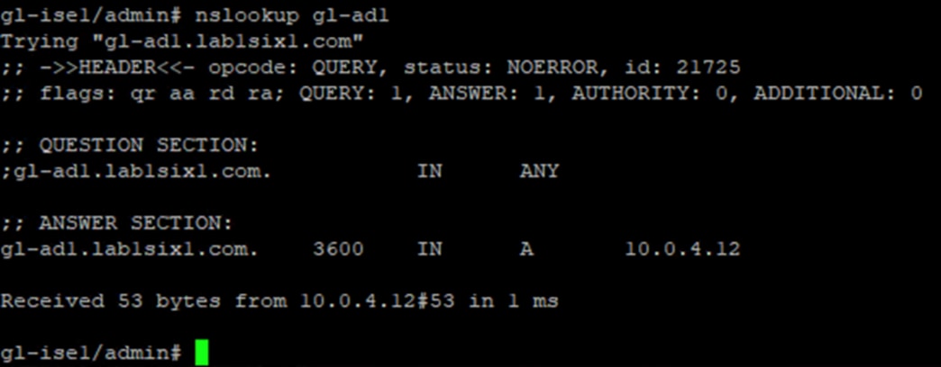
Step 4. From the ISE CLI, confirm DNS name resolution for the AD server via the nslookup command:
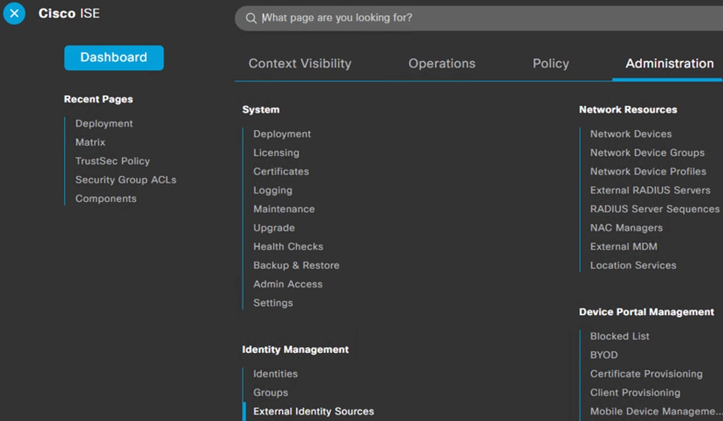
Step 1. From the ISE GUI, click the Menu icon (![]() ) and navigate to Administration à Identity Management à External Identity Sources.
) and navigate to Administration à Identity Management à External Identity Sources.
![]()
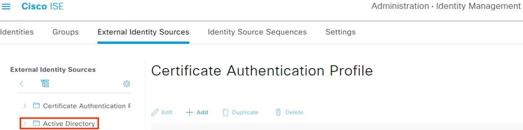
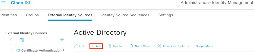
Step 2. Click on Active Directory.
Step 3. Click the Add button.
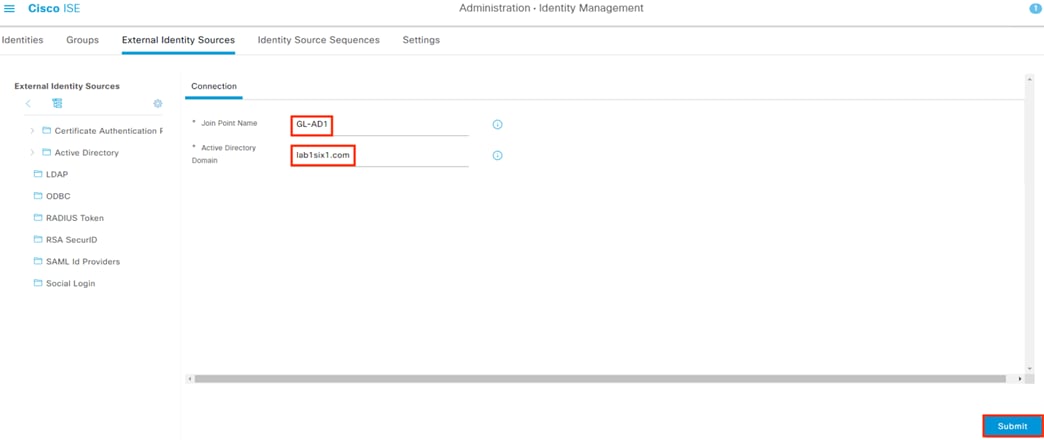
Step 4. Enter a name for the Join Point and specify the domain of the target AD server. Click the Submit button.
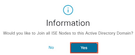
Step 5. A prompt appears asking whether to join immediately. Click Yes. Note: if you accidentally click No, the domain can be joined from the Connection page.
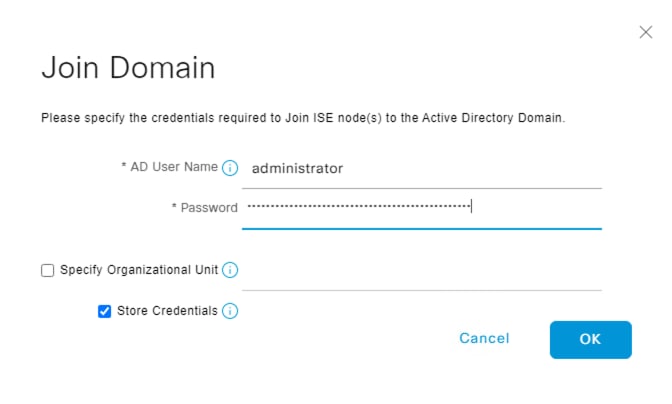
Step 6. Enter an AD administrator username and password. ISE recommends checking the Store Credentials box. Click OK.
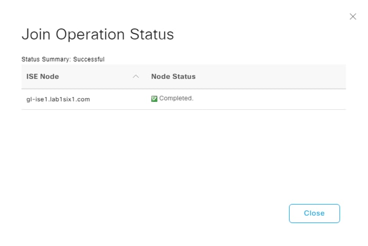
Step 7. If everything is in order, ISE will join the domain. Click Close.
ISE: Import Active Directory Groups
Active Directory groups will be needed for Authentication and Authorization policy rules in a later section, and it makes sense to import them here.
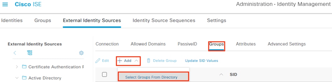
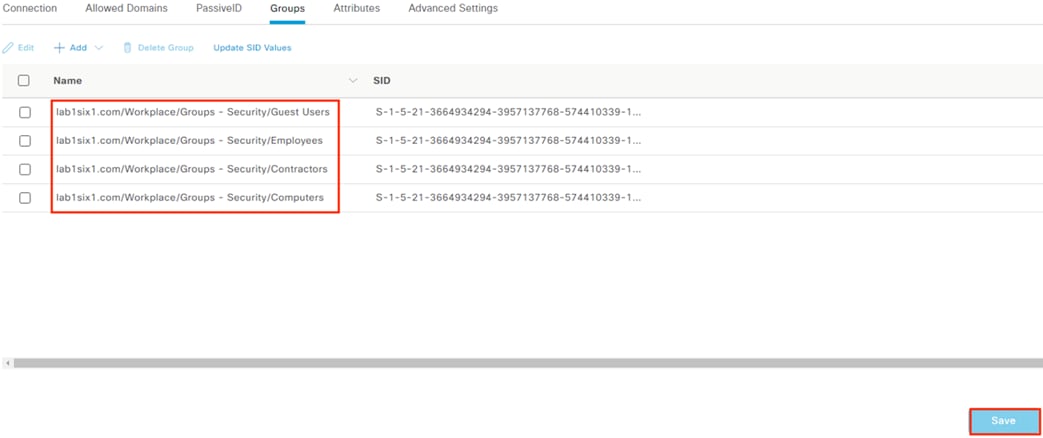
Step 1. From the last screen in the prior section, click the Groups tab (or navigate to Administration à External Identity Management à External Identity Sources à Active Directory à edit à select the Groups tab). Click Add, then click Select Groups from Directory.
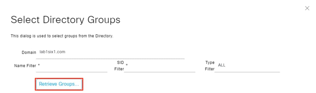
Step 2. The domain will auto-populate. Enter any desired filter criteria or leave the default asterisks and click the Retrieve Groups option.
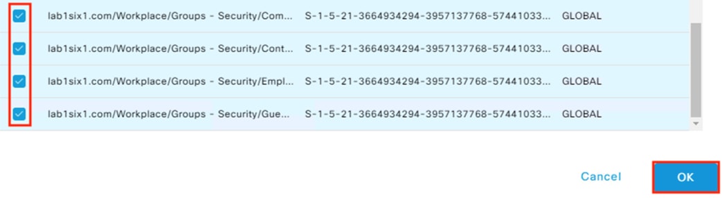
Step 3. Select the desired groups and click the OK button. Note: if 100 groups were retrieved then the list may be truncated. Filter the search if the needed groups are not in the list. For this example, we’ll retrieve groups associated with Employees, Contractors, Guests, and a Computers group that will be used later for machine authentication.
Step 4. The retrieved AD groups are displayed. Click Save.
PassiveID can be used to collect AD logins that do not pass through ISE and redistribute them to security platforms like Secure Analytics and Secure Firewall. As covered in the introduction, a key recommendation is to have end-to-end 802.1X and TrustSec across the network. When this is in place, all initial user connections to the network will be forwarded from a TrustSec capable device to ISE for authentication, rendering PassiveID unnecessary. However, the reality of modern networks is that other types of connections—such as VPN-less—still pass over network architecture and have AD based authentication that does not go through ISE. One example of this is the DNG reverse proxy covered in the Cisco Zero Trust: User and Device Security Design Guide, which provides strong security for access to internet facing resources. Another example is network segments that are not yet TrustSec capable. For such examples, PassiveID can serve as a valuable source of supplementary data, allowing additional tracking of user activity in centralized monitoring tools such as Secure Analytics. However, PassiveID cannot provide the strong access control and remediation capabilities of 802.1x and TrustSec, and both should be used wherever possible.
If PassiveID is not desired for deployment, skip to the pxGrid Configuration and Integration section.
ISE: Enable Passive Identity and pxGrid Services on the Policy Server (PSN)
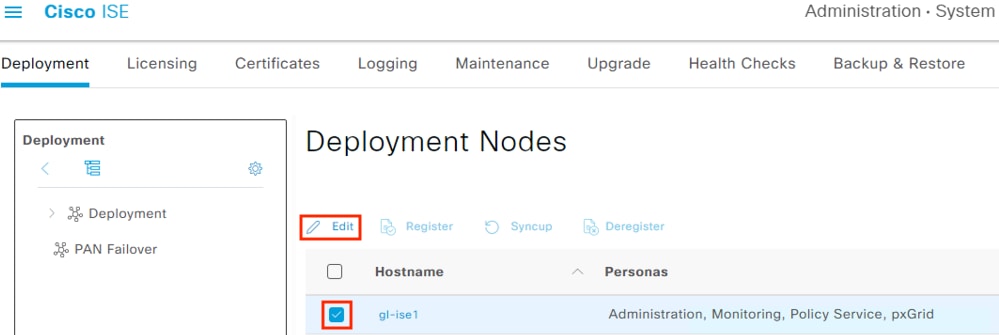
Step 1. From the ISE GUI, click the Menu icon (![]() ) and navigate to Administration à System à Deployment.
) and navigate to Administration à System à Deployment.
Select the PSN that will be connecting to AD then click Edit.
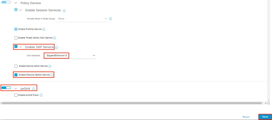
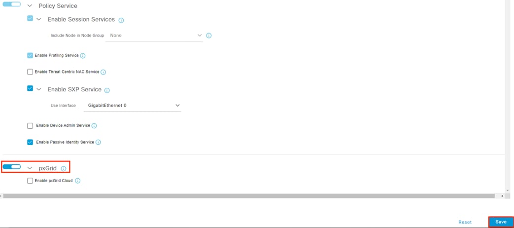
Step 2. Scroll down and check the box next to Enable Passive Identity Service. While you’re here, you can also verify that SXP and pxGrid are enabled since they will be used in later sections. Click Save.
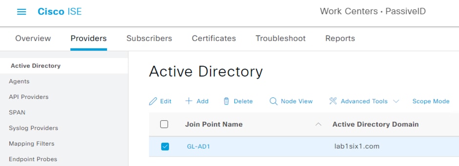
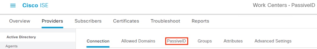
Step 1. Click the Menu icon (![]() ) and navigate to Work Centers à PassiveID à Providers.
) and navigate to Work Centers à PassiveID à Providers.
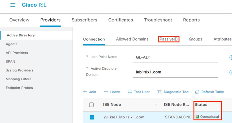
Step 2. Select Active Directory from the left menu and check the box next to the Join Point created previously. Click Edit.
Step 3. Review the connection details and confirm the Status is Operational. Click the PassiveID tab.
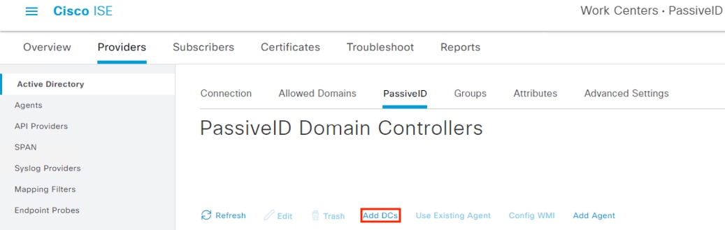
Step 4. Click the Add DCs link.
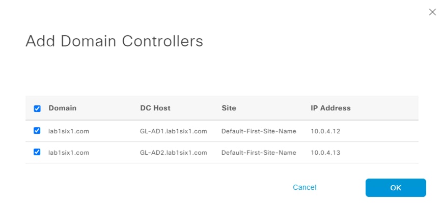
Step 5. Click the boxes next to each DC you would like to add to the join point for monitoring and then click the OK button.
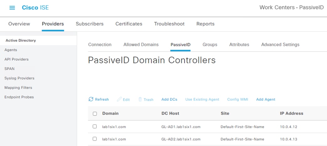
The PassiveID page should now display the added DCs.
ISE: Configure Microsoft Remote Procedure Call (MSRPC) for PassiveID
ISE 3.0 and above supports MSRPC for Passive Identity. Note that while Windows Management Instrumentation (WMI) can still be used, there are some complications associated with Windows DCOM Server Security per CVE-2021-26414. This guide will use an agent and MSRPC as the Passive Identity source. Note that this requires the installation of an agent on the Domain Controller(s).
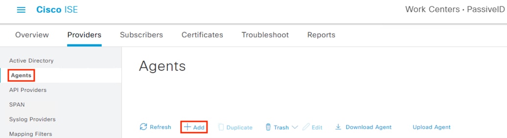
Step 1. Click the Menu icon (![]() ) and navigate to Work Centers à PassiveID à Providers.
) and navigate to Work Centers à PassiveID à Providers.
Step 2. Click the Agents tab, then click Add.
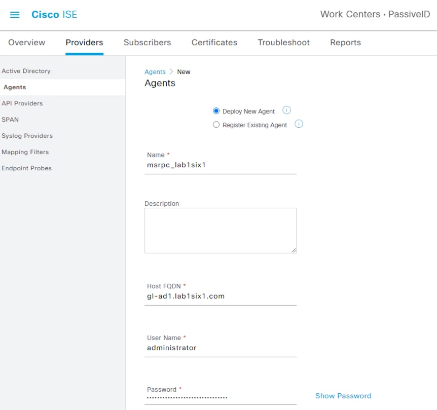
Step 3. Select Deploy New Agent and populate the FQDN, AD admin username and password, set MS-RPC as the protocol, and specify High Availability settings (a Primary + Secondary is recommended if a suitable AD deployment is available). Click Deploy.

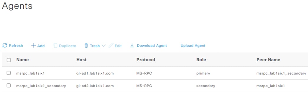
The new agent is shown after successful deploy. The prior steps can be repeated to deploy a secondary agent, if desired (when selecting the Secondary agent option, an additional field will populate to specify the primary agent).
ISE: Map Domain Controllers with MSRPC Agents
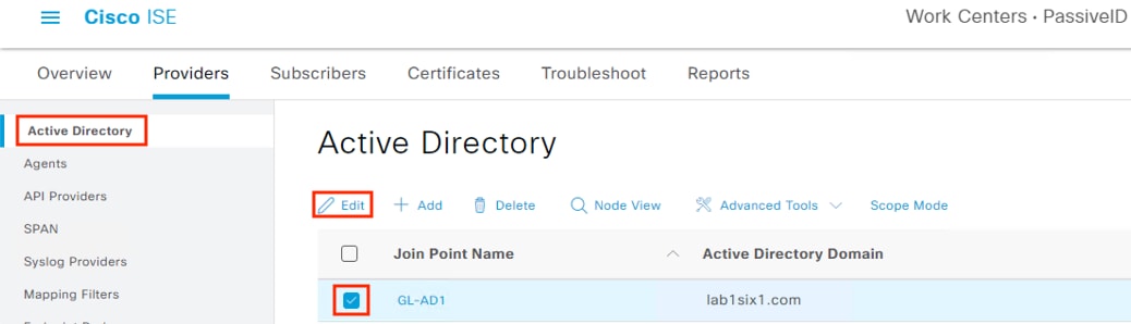
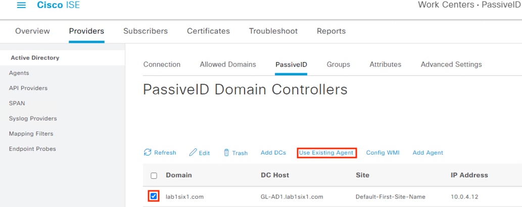
Step 1. From the prior section, click on Active Directory (or navigate to Work Centers à PassiveID à Providers à Active Directory). The domain that was joined previously should be visible. Select the Join Point and click Edit.
Step 2. Click the PassiveID tab.
Step 3. This deployment has an active and secondary DC. In this example, we select the primary DC added in the prior section and click Use Existing Agent.
Step 4. Select the primary DC agent and click OK.
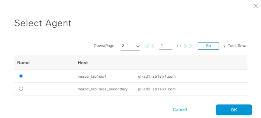
Repeat the process to associate the secondary agent with the secondary DC, if applicable.
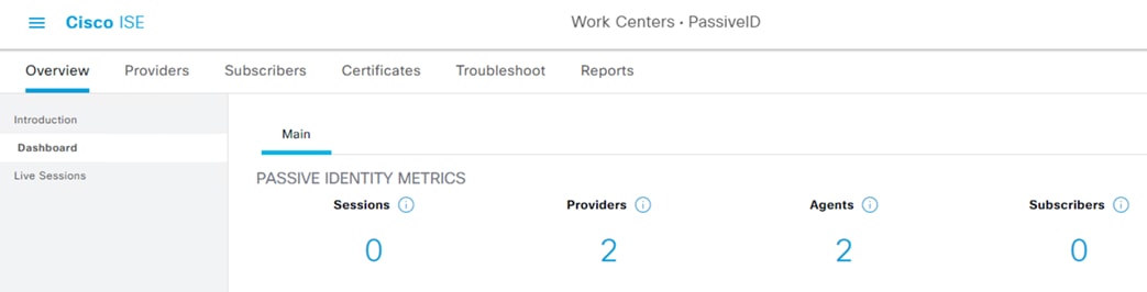
ISE: Validate the PassiveID Deployment
Step 1. To verify the DC providers and agents from the PassiveID Work Center, click on Overview à Dashboard. Provider and Agent counts should match the prior configuration.
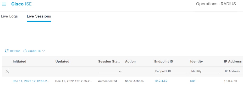
Step 2. User to IP associations can be viewed either from Work Centers à PassiveID à Overview à Live Sessions or via Operations à RADIUS à Live Sessions.
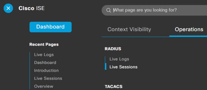
The Live Sessions page shows active user to IP mappings. Note that you’ll need a successful user authentication to one of the monitored DCs before entries will populate.
pxGrid Configuration and Integration
For this design, pxGrid functions as the communication channel between ISE and Secure Firewall, and between ISE and Secure Network Analytics. pxGrid is used to transmit user to IP mappings from ISE to pxGrid clients, and for ISE to receive quarantine designations that ISE can then use to revoke network access via connected switches. Quarantine functionality for one pxGrid client, Secure Network Analytics, is covered in the Adaptive Network Control section.
Steps to enable pxGrid were covered in the PassiveID section.
Step 1. To confirm the settings, click the Menu icon (![]() ) and navigate to Administration à System à Deployment.
) and navigate to Administration à System à Deployment.
Step 2. Check the box next to the relevant node(s) and then click Edit.
Step 3. Scroll down and verify that pxGrid is enabled, then click Save if changes were made.
ISE: Configure Subscriber Settings
Step 1. Click the Menu icon (![]() ) and navigate to Administration à pxGrid Services à Settings.
) and navigate to Administration à pxGrid Services à Settings.
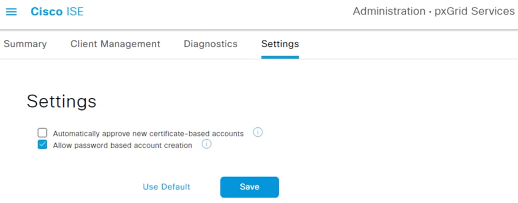
The settings page offers two options: (1) automatically approve new clients that present the pxGrid certificate, or (2) manually approve accounts based on username and password. This guide will use the password option, but the automatic option can be selected for ease of use.
Step 2. Select an option then click Save.
Certificate Requirements for pxGrid Subscribers
Secure Firewall Management Center (FMC) and Secure Network Analytics have different requirements for the pxGrid connection.
· The FMC requires an FMC client certificate + private key pair for the connection from the FMC to ISE, and the client certificate must be signed by a root CA that is trusted within ISE. In addition, the FMC must have the root certificate(s) used to sign the ISE pxGrid certificate and the ISE MnT server certificate. The ISE pxGrid certificate and the ISE MnT server certificates cannot be self-signed.
· Secure Network Analytics requires a client certificate for the connection to ISE, signed by a root CA that is trusted within ISE for authentication.
The certificates to collect for the above connections can vary depending on ISE deployment and ISE certificate configuration. This section will cover certificate identification steps for building the pxGrid connection. Steps for installing pxGrid client certificates created through both ISE and AD are included in this section. Steps for creating and installing CA signed certs and creating CA templates for client and server auth certificates in Active Directory are included in the SAFE Certificate Management Design Guide.
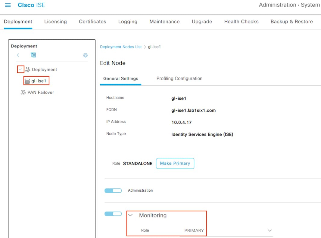
ISE: Identify the Primary Monitoring (MnT) Node
MnT node configuration can vary by ISE deployment. To verify which node has MnT functionality, perform the following steps.
Step 1. Click the Menu icon (![]() ) and navigate to Administration à System à Deployment.
) and navigate to Administration à System à Deployment.
Step 2. Expand the dropdown arrow next to Deployment and review the available nodes. Click on the available nodes and verify which one has the primary Monitoring role, as shown below.
ISE: Review Certificate Details
The steps for meeting the pxGrid certificate requirements in the prior section will vary depending on the ISE deployment and the certificates in use. This section covers how to review the certificates deployed; steps to export certificates for different deployment scenarios are covered in the SAFE Certificate Management Design Guide.
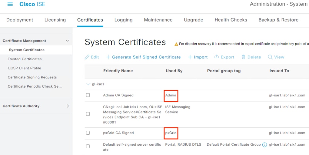
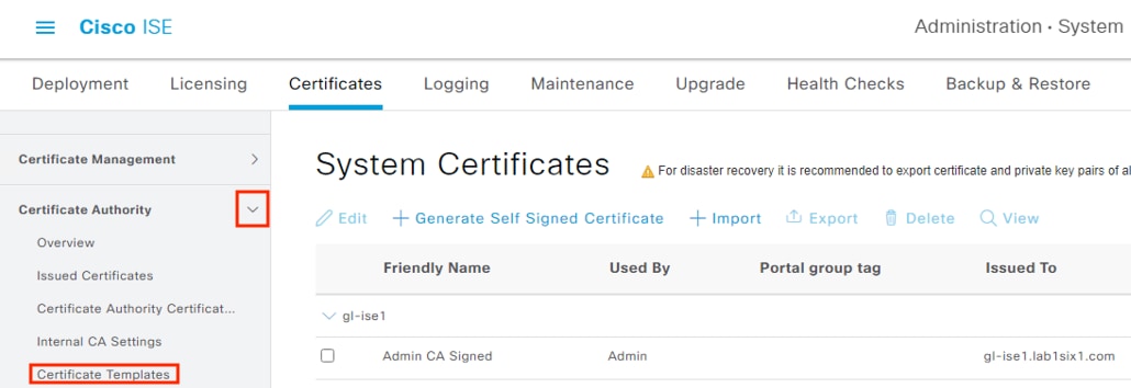
Step 3. Click the Menu icon (![]() ) and navigate to Administration à System à Certificates.
) and navigate to Administration à System à Certificates.
Step 4. Identify the Admin certificate issued to the primary MnT node and the pxGrid certificate via the Used By column.
Note: The certificates are both on the same ISE node in this example, but they could be on separate nodes depending on the deployment.
Note: The default starting configuration for ISE will assign multiple areas of functionality to a single certificate.
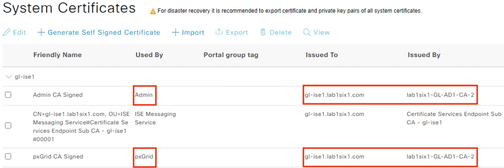
Step 5. After identifying the Admin certificate for the MnT server and the pxGrid certificate, confirm whether the Issued To and Issued By fields are different. If the Issued To and Issued By fields are different for a certificate, then the certificate was signed by a CA and is not self-signed (reminder that a self-signed certificate cannot be used for the FMC connection). In the example below, both certificates have been issued to the ISE node by an external CA.
Step 6. If needed, select a certificate and click the View or Export options to see additional details on the certificate.
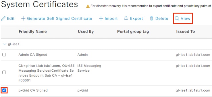
The certificate example below shows the root certificate at the top of the hierarchy. This root certificate corresponds to the Issued By column in the prior screenshots, and the second entry corresponds to the Issued To column in the prior screenshots.
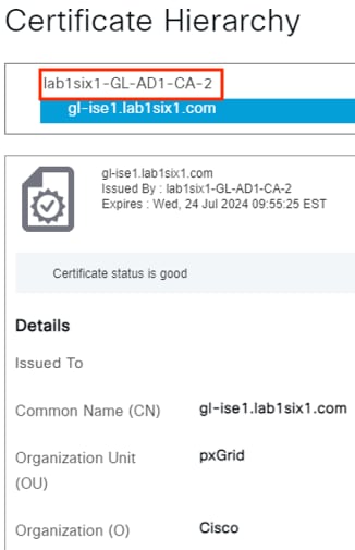
The root certificate highlighted in red above (and appearing in the Issued By columns for both certificates in the prior screenshots) needs to be exported for the Secure Firewall pxGrid connection.
In this example the root certificate for both the Admin and pxGrid certificates is the same, so we only need to export one root certificate instead of two (if the Admin and pxGrid certificates were signed by different root certificates then we would need to export both). The root certificate in the Issued By column could be from an external CA, an ISE CA, or be self-signed.
The companion SAFE Certificate Management Design Guide has procedures for certificate management of different deployment scenarios. For steps to retrieve a root certificate from an AD server CA, please see the section Active Directory Certificate Authority: Export a Root Certificate.
For steps to retrieve an ISE root certificate, please see the section ISE: Export an ISE Root Certificate.
If the Issued To and Issued By fields are the same for either certificate, then the certificate is self-signed; the pxGrid integration with Secure Firewall will fail if either certificate is self-signed. If it is necessary to import externally signed certificates into ISE to replace self-signed certificates, please see the sections starting with ISE: Generate Certificate Signing Request for the pxGrid Role and ending with the section ISE: Bind Certificates to CSR Requests and Assign Certs to Roles.
Step 7. Once the root certificate for the MnT Server and pxGrid certificates have been obtained, save them in an accessible folder. Procedures for generating and importing the client certificates for Secure Firewall and Secure Network Analytics are covered in the following sections.
pxGrid Client Certificate Methodology
In addition to the root certificate(s) covered in the prior section, Secure Firewall and Secure Network Analytics both require client certificates for the pxGrid connection. The sections following this one detail two methods for generating and installing the pxGrid client certificate.
● For Secure Firewall, methodology is provided for creating a pxGrid client certificate template in ISE, and using the template to create a pxGrid client certificate signed by an ISE CA.
o Some users will prefer to generate a Certificate Signing Request (CSR) via OpenSSL and sign with an external CA; if you’re one of them, skip ahead to the Secure Firewall: Install pxGrid Client Certificate section.
● For Secure Network Analytics, methodology is provided to generate a CSR within Secure Network Analytics and then create a certificate using the CSR via an Active Directory CA.
o This method is recommended to ensure the CSR is generated with the specific fields required by Secure Network Analytics. An external CA is also recommended to ease future maintenance of the Secure Network Analytics Trust Store.
ISE: Modify the ISE pxGrid Certificate Template
ISE has a built-in portal that can be used for generating ISE CA signed certificates for pxGrid clients. While this section can be ignored for users who prefer to generate CSRs via OpenSSL, it is worth filling out the template for any user who will use ISE to create pxGrid client certificates on an ongoing basis.
Step 1. In the Cisco ISE GUI, click the Menu icon (![]() ) and choose Administration à System à Certificates.
) and choose Administration à System à Certificates.
Step 2. On the left menu, select expand Certificate Authority and then click Certificate Templates.
Step 3. Check the box next to pxGrid_Certificate_Template and then click Edit.
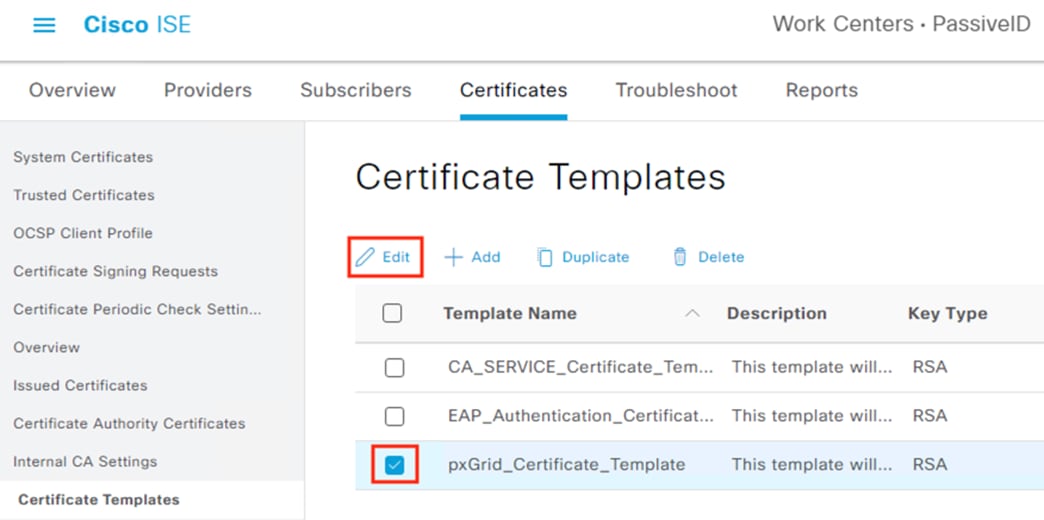
Step 4. Fill in the certificate details as applicable and change the Key Size and Valid Period if desired. Click Save when finished.
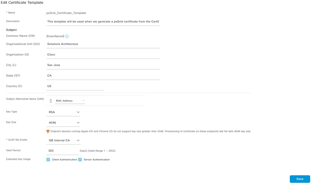
The template will be used in the next section.
ISE: Generate pxGrid Client Certificate for Secure Firewall
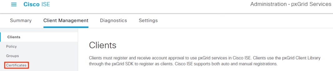
Step 1. In the Cisco ISE GUI, click the Menu icon (![]() ) and choose Administration à pxGrid Services à Client Management.
) and choose Administration à pxGrid Services à Client Management.
Step 2. Select Certificates from the left menu.
Step 3. Populate all the required fields and Subject Alternative Name (SAN) entries for the client device, if desired. The example below specifies the Common Name (CN), Fully Qualified Domain Name (FQDN), and SAN field entries for a FMC. The ‘I want to’ field is set to generate a certificate without a CSR, but this field also has an option to import a previously generated CSR file. Note that the pxGrid Certificate Template configured in the last section is used here. Finally, the option to generate the certificate in PKCS8 PEM format has been selected. This will generate a group of certificates and a key in a format that can be uploaded to the FMC.
Note: The password, which will be used when importing the key file later.
Step 4. Click Create.
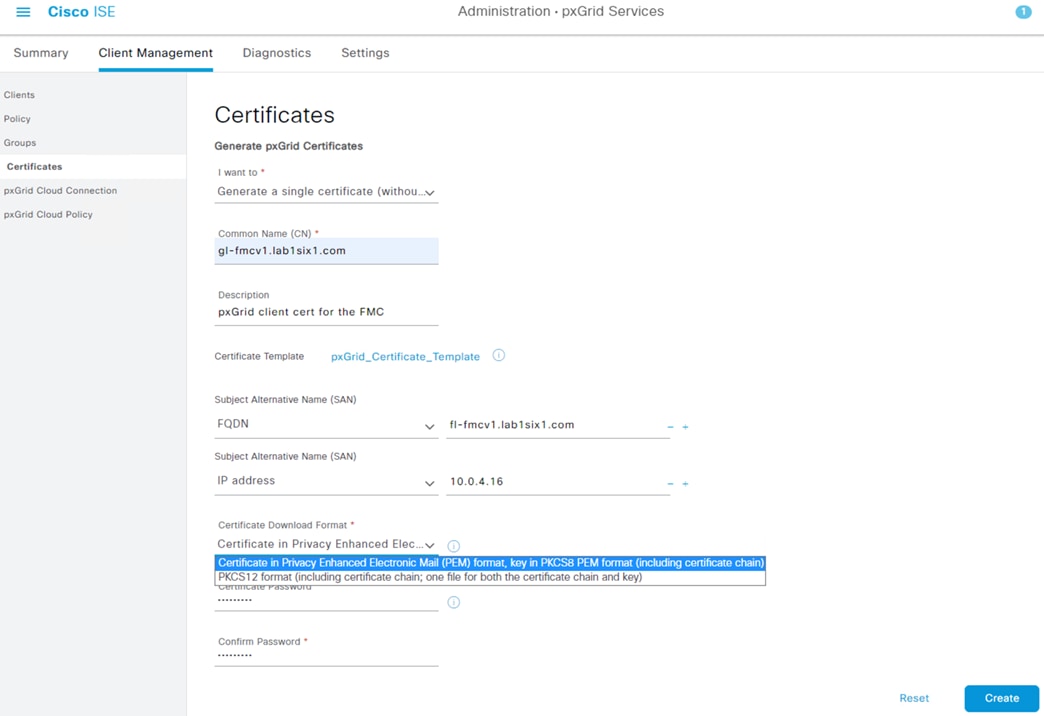
The files will download as a zip folder.
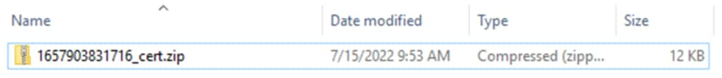
Extracting the zip file will display a certificate, four ISE chain certificates, and a key. The highlighted certs and key can be used to add ISE as an identity source in the FMC.
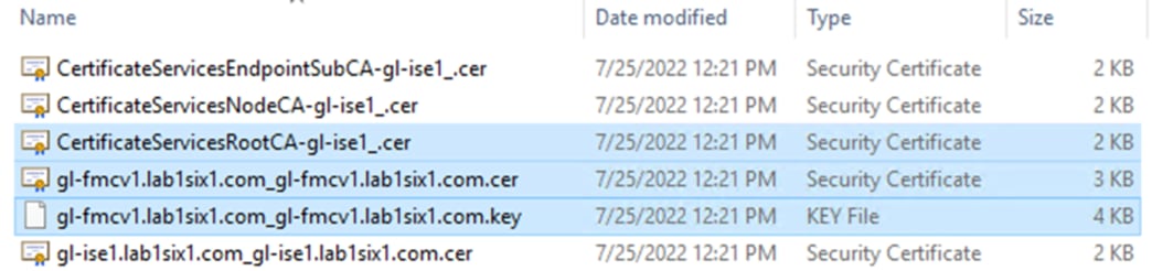
The first highlighted entry is the root certificate (note the RootCA text) that ISE used to sign the generated pxGrid client certificate. The second highlighted entry is the pxGrid client certificate itself. The last highlighted entry is the key associated with the pxGrid client certificate.
Secure Firewall: Install pxGrid Client Certificate
Step 1. In the FMC GUI, navigate to Objects à Object Management.
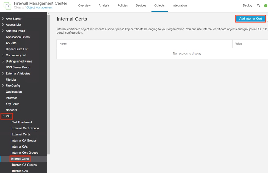
Step 2. Expand the dropdown for PKI in the left side menu, then click Internal Certs. Click the Add Internal Cert button.
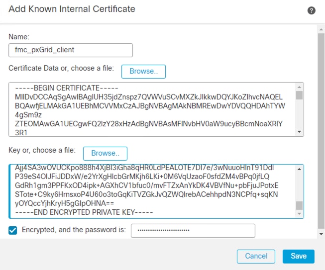
Step 3. Enter a name for the new internal cert and upload the certificate file and associated private key file generated in the prior section (Generate pxGrid Client Certificate for Secure Firewall). Check the Encrypted box and enter the password set during the .pvk file's creation. Remove any text that appears before the BEGIN line or after the END line for either file (the Save option will be greyed out if there is any text before the BEGIN line or after the END line). Click Save.
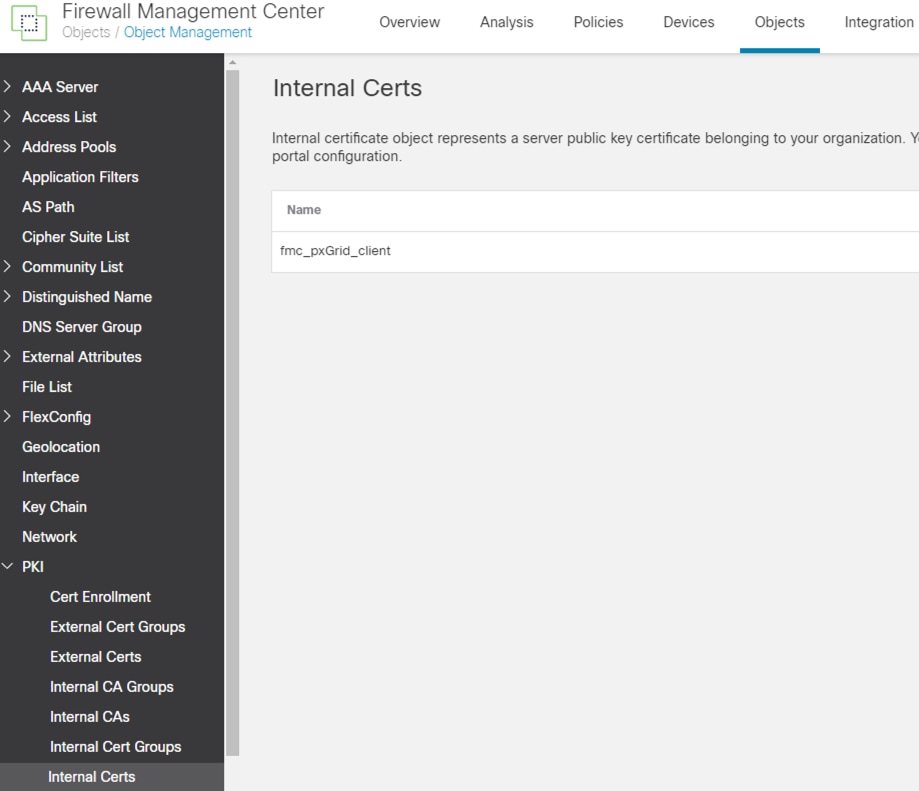
Step 4. Confirm the new certificate is added.
ISE: Import Secure Firewall pxGrid Client Certificate CA
This step is not necessary if the pxGrid client certificate was generated by ISE (as it was in the prior sections, in which case the CA is already trusted by ISE), or if the CA that signed the pxGrid client cert is already imported into ISE as a trusted CA. If neither of those scenarios apply, acquire the root certificate for the pxGrid client certificate and follow the steps in the ISE: Add an External Certificate to the Trusted Certificate Store section.
Secure Firewall: Add the Root Certificate for the ISE MnT Server and pxGrid Certs to the FMC Trust Store
Step 1. Return to the FMC Objects page and click on the Trusted CAs section under PKI, then click the Add Trusted CA button.
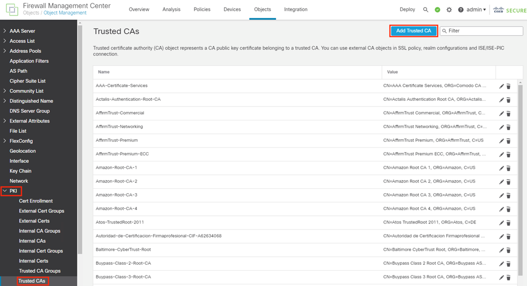
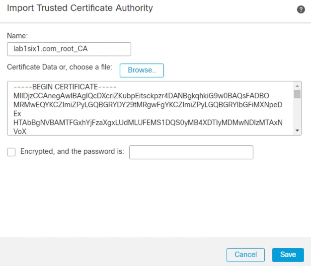
Step 2. Enter a name for the certificate, then upload the root certificate (or certificates) collected in the Generate pxGrid Client Certificate for Secure Firewall section. The uploaded certificate(s) must be the root certificate(s) used to sign the ISE MnT Server and pxGrid certificates. Click Save.
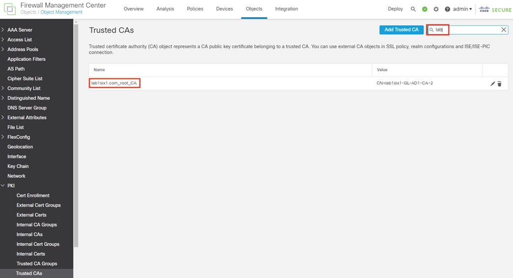
Step 3. If desired, search for the uploaded certificate to confirm successful upload.
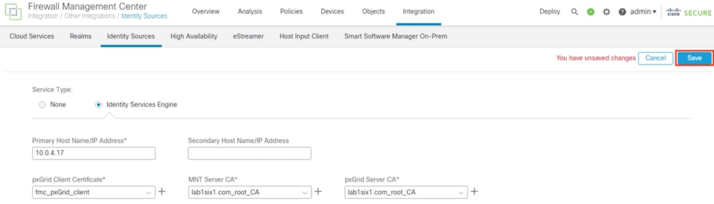
Secure Firewall: Configure ISE as an Identity Source
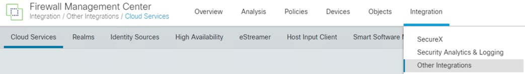
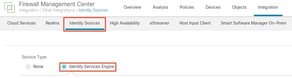
Step 1. From the FMC, navigate to Integration à Other Integrations.
Step 2. Click on Identity Sources, then select the Identity Services Engine radio button.
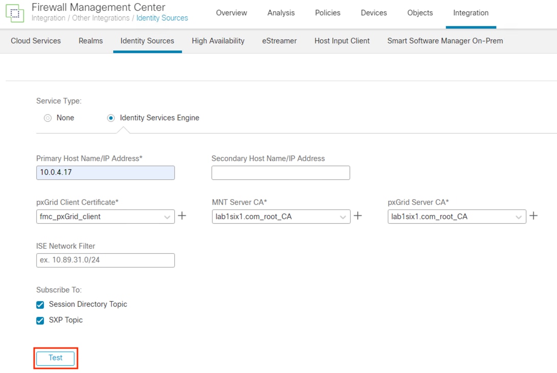
Step 3. Enter the IP or hostname of the primary ISE pxGrid node, and the secondary pxGrid node if applicable. For the pxGrid Client Certificate, select the certificate uploaded in the Install pxGrid Client Certificate section. For the MnT Server CA and pxGrid Server CA, select the certificate(s) uploaded in the Add the Root Certificate for the ISE MnT Server and pxGrid Certs to the FMC Trust Store section. Ensure that Session Directory Topic and SXP Topic are selected. Click the Test button to verify connectivity.
The Test output will show success or failure for the pxGrid connection. The example below shows a connection failure, however expanding the Additional Logs drop down shows that the connection failed because the Subscriber request is pending approval in ISE (this error will not occur if Subscriber requests are automatically approved in ISE).
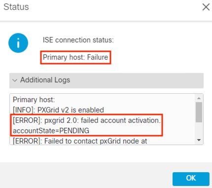
The Test connection can also fail if the FMC does not have a route to ISE, if DNS name resolution for the ISE node fails, if ISE services are not running, or if the three certificates are not correct. For the error above, we only need to approve the Subscriber request in ISE.
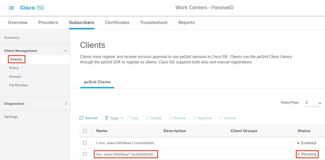
Step 4. If approval is needed, return to the ISE GUI, click the Menu icon (![]() ) and navigate to Work Centers à PassiveID à Subscribers.
) and navigate to Work Centers à PassiveID à Subscribers.
Step 5. Click on Clients. There should be a Pending request from the FMC.
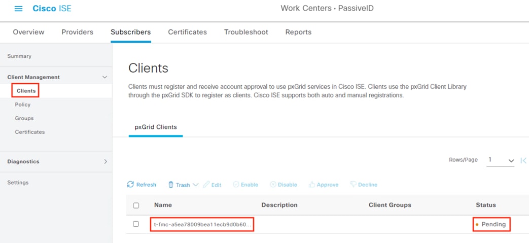
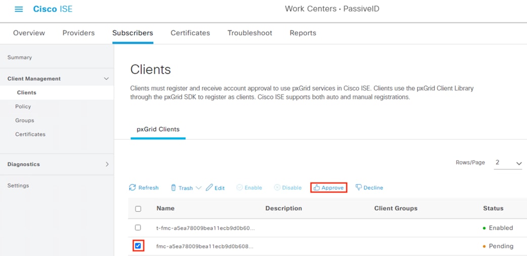
Step 6. Check the box next to the pending entry and then click Approve. Note: this approval is only for the test connection. The FMC will generate a separate request for the saved config.
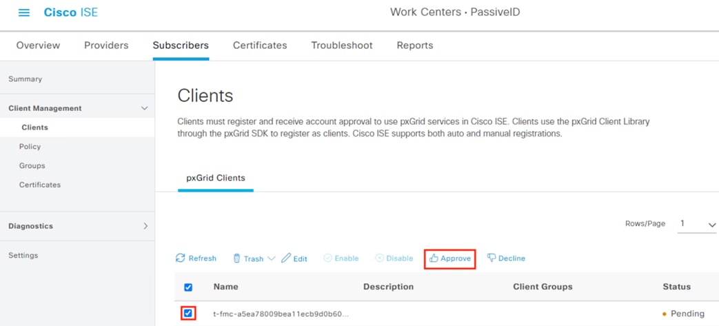
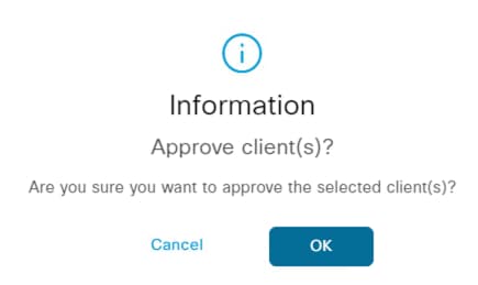
Step 7. A prompt appears asking for confirmation. Click OK.
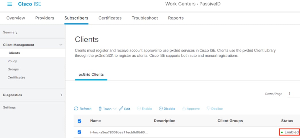
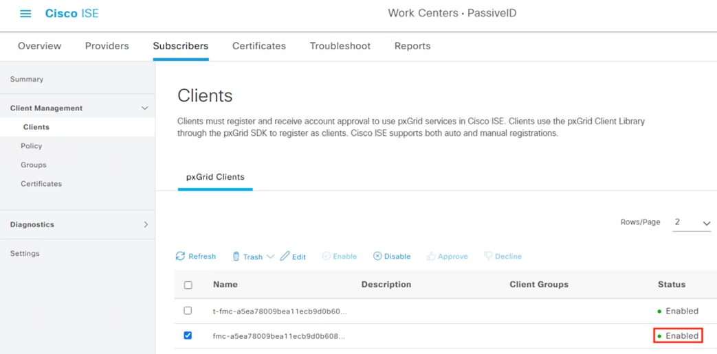
Step 8. Verify the Status changes to Enabled.
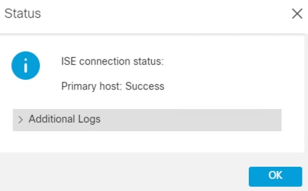
Step 9. Return to the FMC and run the Test again.
Step 10. Status should show Success. If it does not, click the Additional Logs dropdown to troubleshoot.
Step 11. Click OK, then click the Save button to submit the configuration.
Step 12. The saved configuration will also need approval as a Subscriber in ISE. If manual approval is needed, return to the ISE GUI, and navigate to Work Centers à PassiveID à Subscribers.
Step 13. Click on Clients. There should be a new Pending request from the FMC.
Step 14. Check the box next to the pending entry and then click Approve.
Step 15. A prompt appears asking for confirmation. Click OK.
Step 16. Verify the status changes to Enabled.
Secure Firewall: Verify ISE Subscriber Data
Now that Secure Firewall is configured as an ISE Subscriber, the FMC will receive ISE Security Groups for use in Dynamic SGT and user session information that provides user to IP mapping.
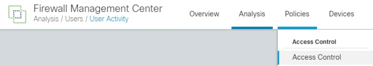
Step 1. In the FMC, navigate to Policies à Access Control.
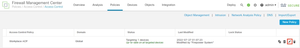
Step 2. Click the pencil icon to edit the applied policy or create a new one.
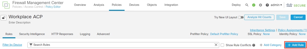
Step 3. Click the Add Rule button.
Step 4. Click on Dynamic Attributes.
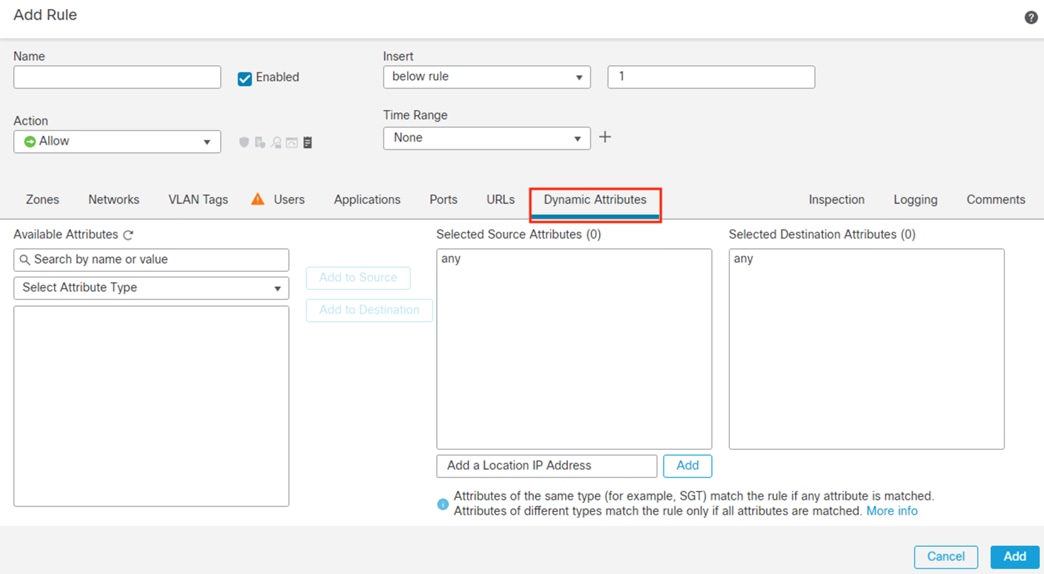
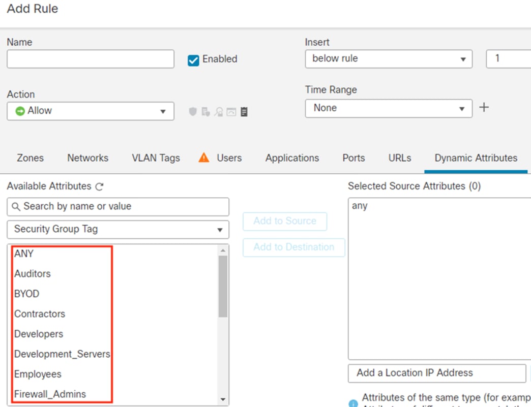
Step 5. Click the dropdown arrow underneath Available Attributes, then select Security Group Tag.
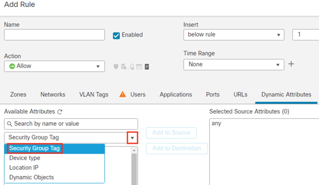
The Available Attributes list will display groups retrieved from ISE that can be used for dynamic SGT.
Secure Network Analytics: Configure pxGrid Integration
This section will create a client certificate that the SMC will use to connect to ISE. While a Secure Network Analytics deployment will run fine with default self-signed certificates, external CA signed certificates are recommended as a best practice and are required for advanced security features such as FIPS. This guide will cover the import of a root CA certificate into the Secure Analytics Trust Store and the creation of an externally signed pxGrid client certificate.
Note: It is possible to use ISE as a CA for this process if another external CA is not available, but a domain wide CA is recommended.
Active Directory and Secure Analytics: Export CA Root Certificate
You should already have the CA root certificate from a prior step, but if not retrieve it now.
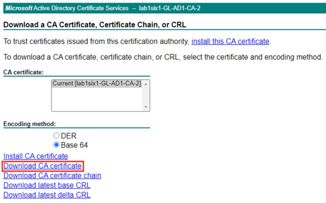
To export a root certificate from an Active Directory CA, Access the CA server by appending /certsrv/ to the AD server hostname, e.g.
· adserver.example.com
· adserver.example.com/certsrv/
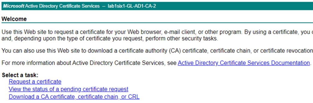
Step 1. Click the Download a CA certificate, certificate chain, or CRL option.
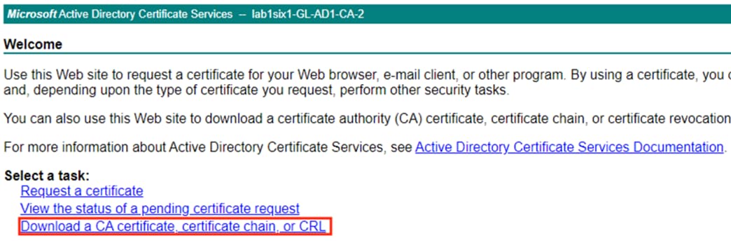
Step 2. Set the encoding method if desired, then click Download CA certificate.
Secure Analytics: Import Root CA Certificate into the Trust Store
Note: This section will result in an appliance reboot. If necessary, schedule a change window before performing these steps.
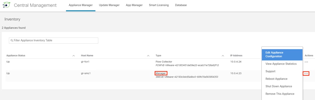
Step 1. From the SMC GUI, click the gear icon and select Central Management.

Step 2. Identify the primary Manager, click the ellipses, and select Edit Appliance Configuration.
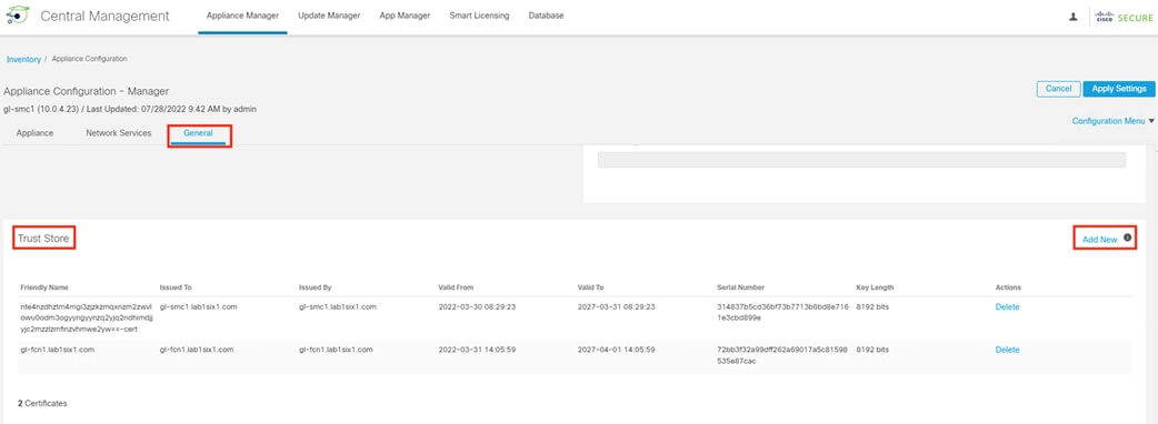
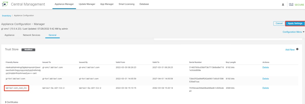
Step 3. Click the General tab and scroll down to the Trust Store. Click Add New.
Step 4. Enter a friendly name for the certificate, select the certificate file, then click Add Certificate.
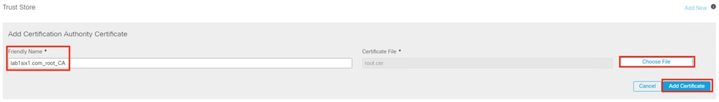
Step 5. The new certificate will immediately appear in the Trust Store. Click Apply Settings.
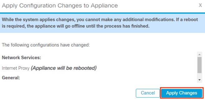
Step 6. Note the reboot warning, then click Apply Changes again if the change can proceed.
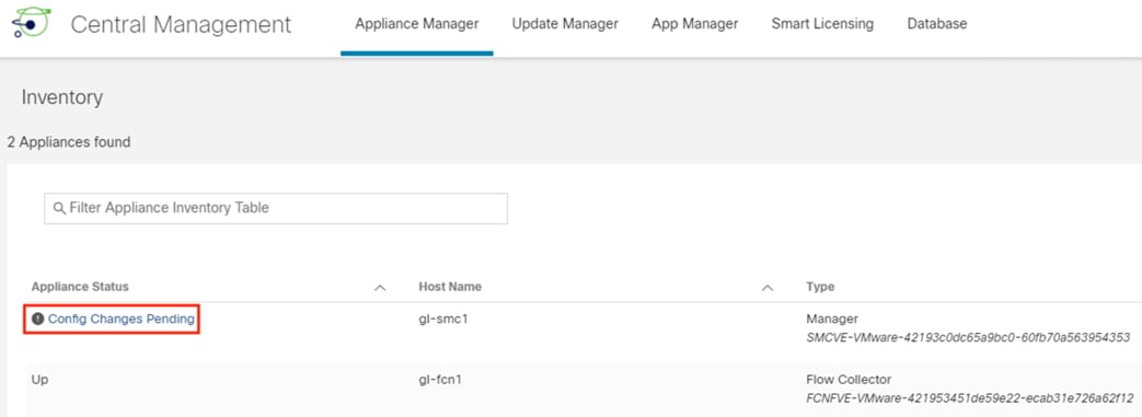
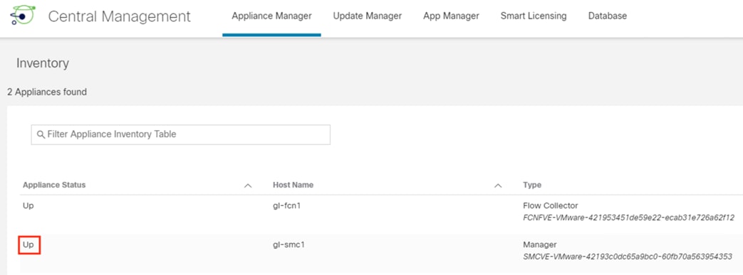
Step 7. Wait for Appliance Status to change from Config Changes Pending to Up before proceeding.
While not required, it is recommended to import the root certificate into the Trust Stores of the other Secure Analytics appliances for future use.
Secure Analytics and Active Directory: Generate and Sign a pxGrid Client Certificate
Note: This section uses an AD CA certificate template with the Client Authentication and Server Authentication fields. If you don’t have one already, please see the section Active Directory: Create a Client and Server Authentication Template before proceeding.
Step 1. From the SMC GUI, click the gear icon and select Central Management.

Step 2. Identify the primary Manager, click the ellipses, and select Edit Appliance Configuration.

Step 3. From the Appliance tab, scroll down to the Additional SSL/TLS Client Identities section, then click Add New.
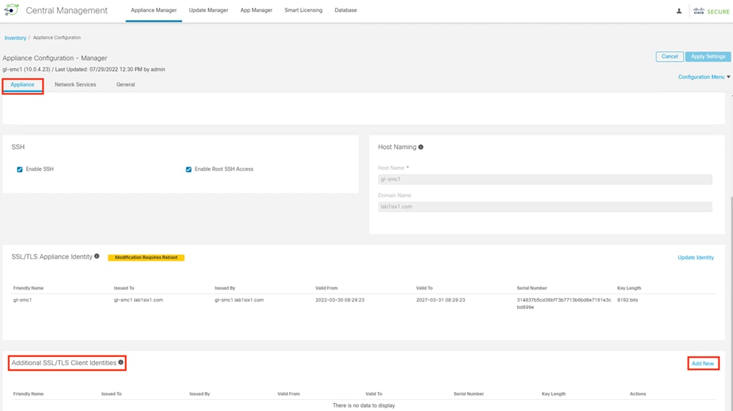
Step 4. Select the radio button for Yes to generate a CSR, then click Next.
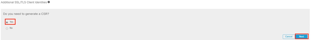
Step 5. Select an RSA Key Length and fill in certificate details as desired. Click Generate CSR.
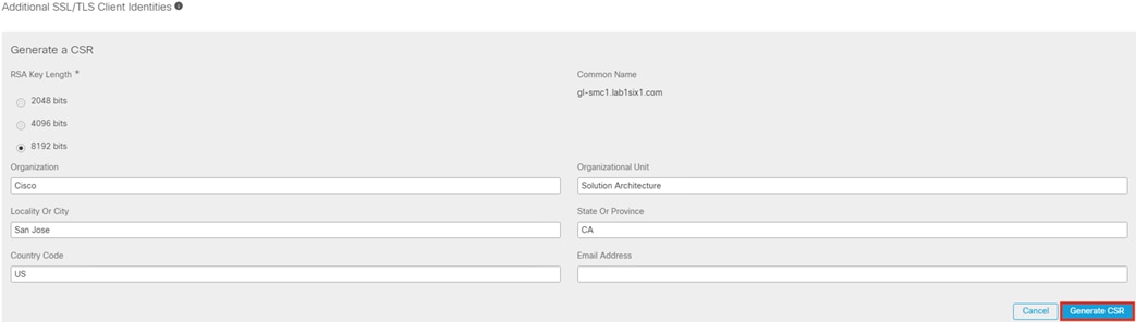
Step 6. When the generation process completes, click the Download CSR button, and save the file.
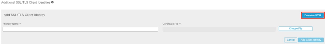
Step 7. Access the CA server and click on Request a certificate.
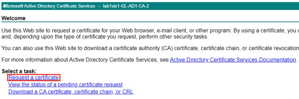
Step 8. Select the advanced certificate request option.
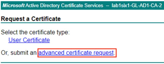
The advanced certificate request page prompts for entry of a CSR in text format.
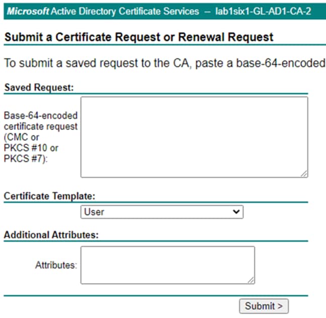
Step 9. Locate the CSR file to upload and open with a text editor (right-click the CSR file and select ‘Open with…’ if the CSR is not associated with a text editor by default).
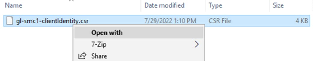
Step 10. Copy the entire block of text starting with the BEGIN line and ending with the END line.
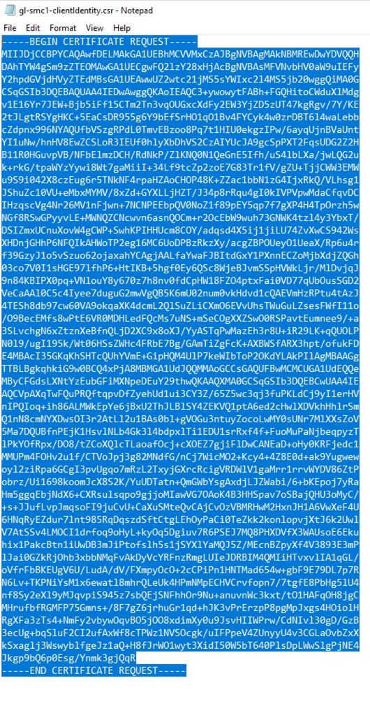
Step 11. Return to the CA server and paste the copied text into the Request field. The certificate must be generated with Client Authentication and Server Authentication fields. If needed, create a suitable template using the steps in the Create a Client and Server Authentication Template section. Click Submit.
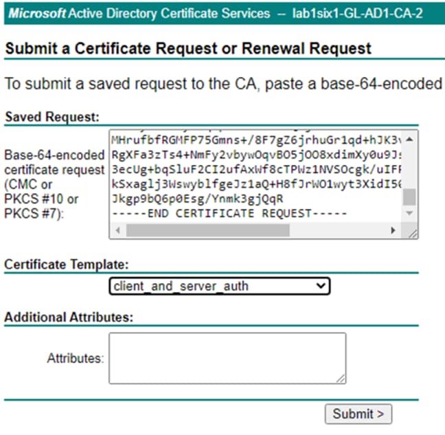
Step 12. Select Base 64 encoded and click Download certificate. It is recommended to give the certificate a clear name that describes its device and purpose.
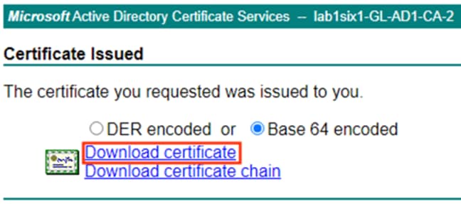
Step 13. Return to the Additional SSL/TLS Client Identities for the SMC. Enter a friendly name for the certificate, choose the file, and click Add Client Identity.
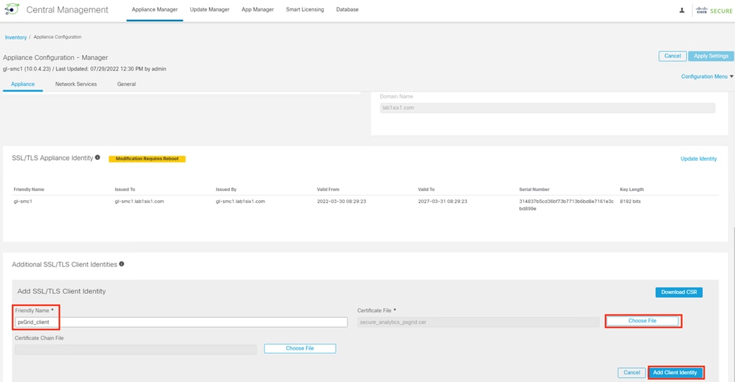
Step 14. The new identity will appear. Click Apply Settings.
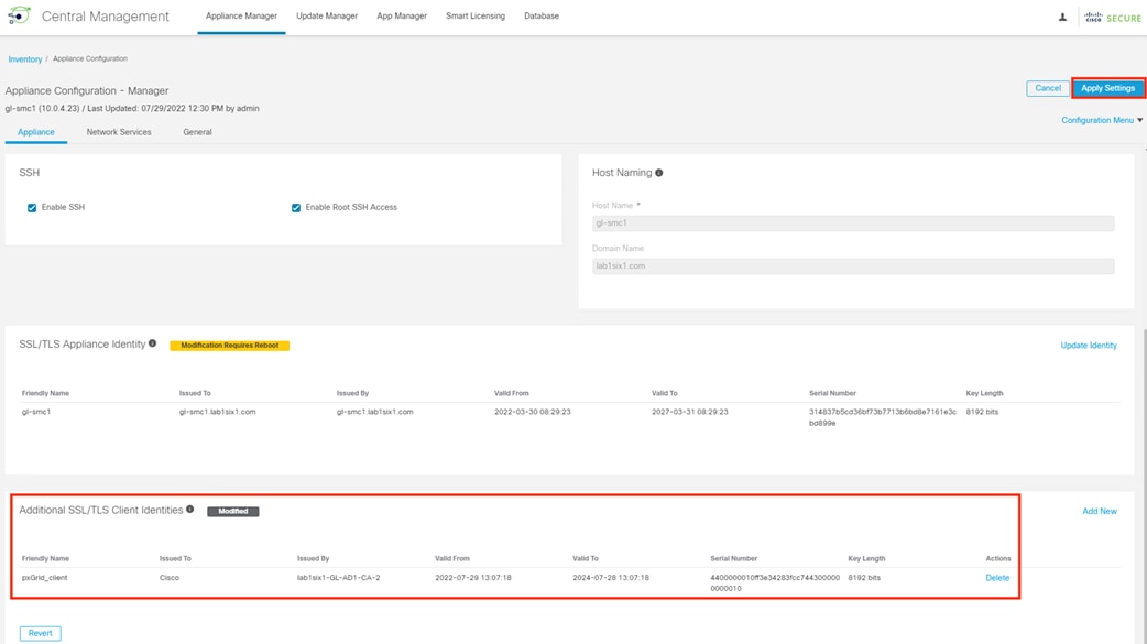
Step 15. Click Apply Changes.
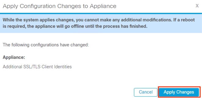
Step 16. Wait for Appliance Status to change from Config Changes Pending to Up.
Secure Analytics and ISE: Configure pxGrid and ANC
Step 1. From the SMC, click on Deploy à Cisco ISE Configuration.
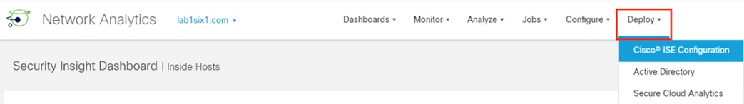
Step 2. Click the ‘Add new configuration’ button.
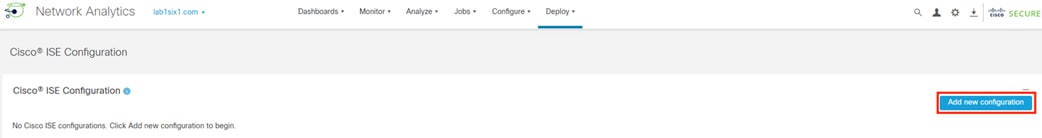
Step 3. Under Certificate, select the certificate that was added in the prior section. Enter IP or host information for the pxGrid node(s) and name the cluster and client. Under Integrated Product, select the Cisco ISE radio button and check the boxes for Adaptive Network Control, Static SGT Classifications, and Sessions. If desired, check the box for Track sessions derived from machine authentication. Click Save.
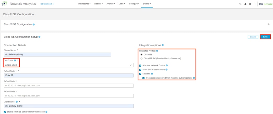
Step 4. Review Status. The Status will show as yellow if the client request is pending approval in ISE.
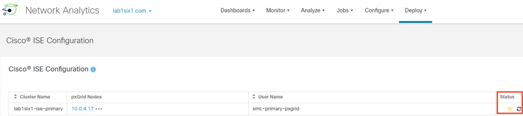
Step 5. In ISE, navigate to Administration à pxGrid Services à Client Management.
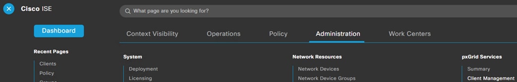
Step 6. A new client for the SMC should be visible. In this example, the client is pending approval.
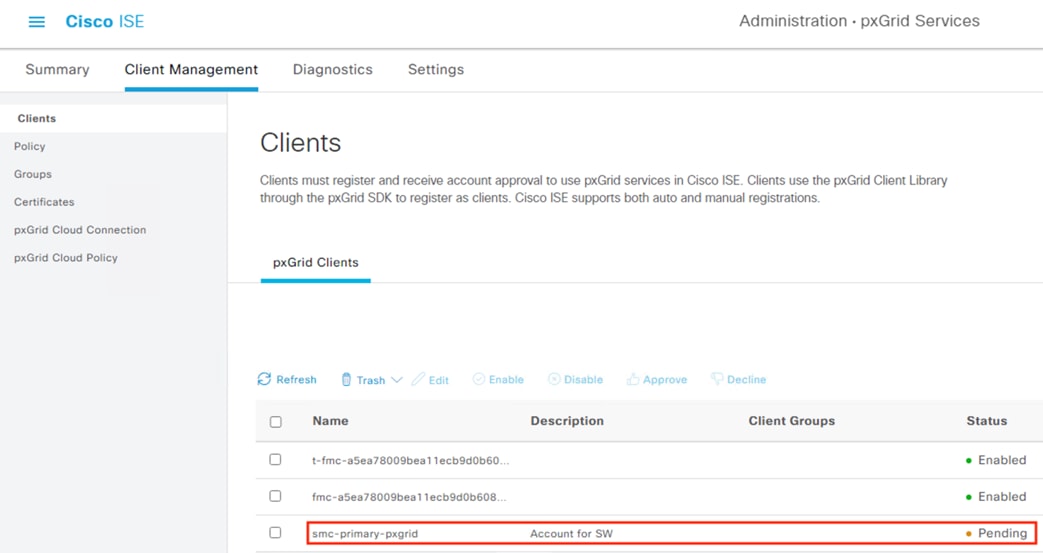
Step 7. Select the SMC client request and click Approve.
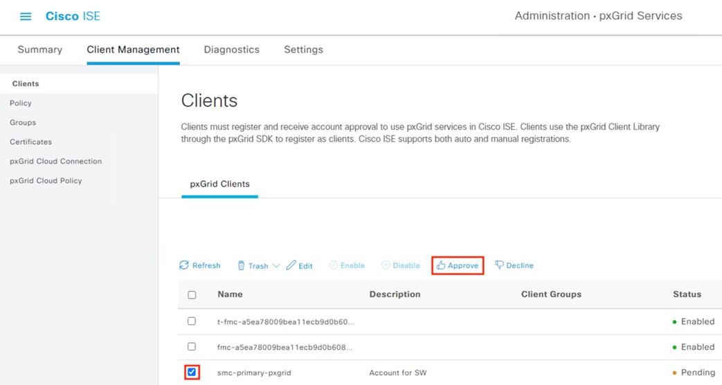
Step 8. Verify the client is enabled.
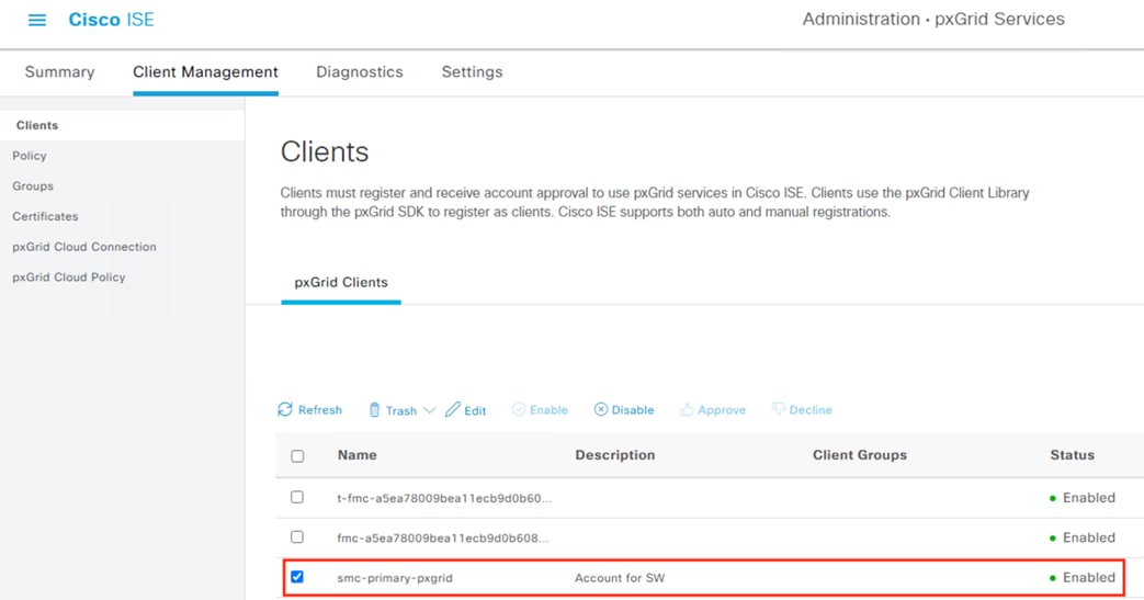
Step 9. Return to the SMC and click refresh.

Step 10. Client status should turn to green, confirming successful integration.
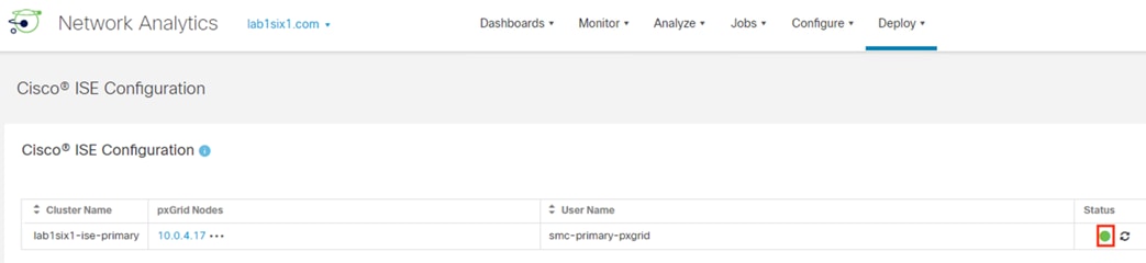
Adaptive Network Control Configuration
The pxGrid communication channel between Secure Analytics and ISE was configured in the prior section with the ANC feature. Additional ISE side configuration is necessary to fully utilize the ANC functionality. The configuration is covered in the following sections.
ISE: Add Secure Analytics to Adaptive Network Control (ANC) Client Group
Step 1. Click the Menu icon (![]() ) and navigate to Administration à pxGrid Services à Client Management.
) and navigate to Administration à pxGrid Services à Client Management.
Step 2. Check the box next to the SMC client added previously and then click Edit.
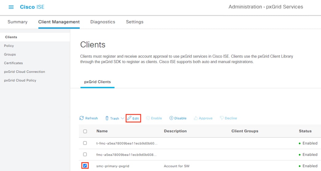
Step 3. Click the drop-down arrow for Client Groups and select ANC. Click Save.
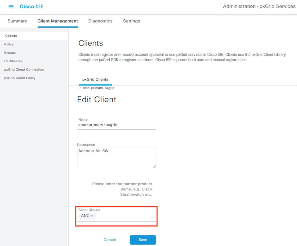
Step 4. ANC will now appear under the Client Groups column for the SMC.
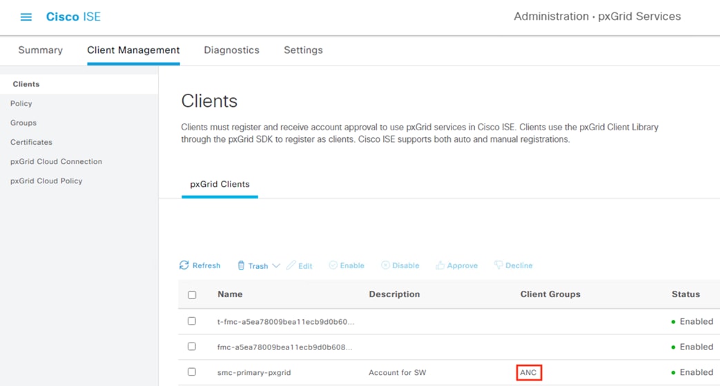
ISE: Configure ANC Policy List
Step 1. Click the Menu icon (![]() ) and navigate to Operations à Adaptive Network Control.
) and navigate to Operations à Adaptive Network Control.
Step 2. Click the Add button.
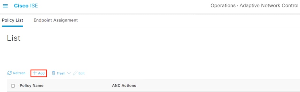
Step 3. Name the Policy List and add QUARANTINE under actions. Note: it is recommended to name this policy ‘Quarantine’; there are several steps involved in tying the action to the network isolation outcome. Click Submit.
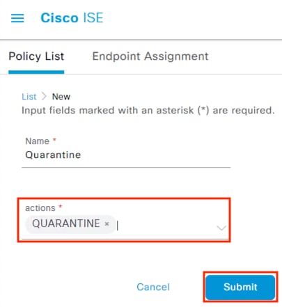
Step 4. The Policy Name and ANC Action will populate.
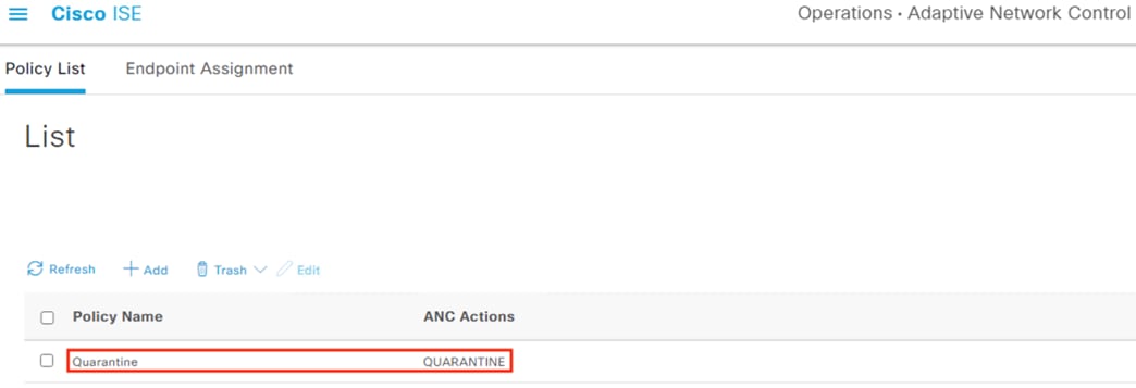
ISE: Add ANC Policy to ISE Authorization Policy
Step 1. Navigate to Policy à Policy Sets.
Click on > to view the desired policy.
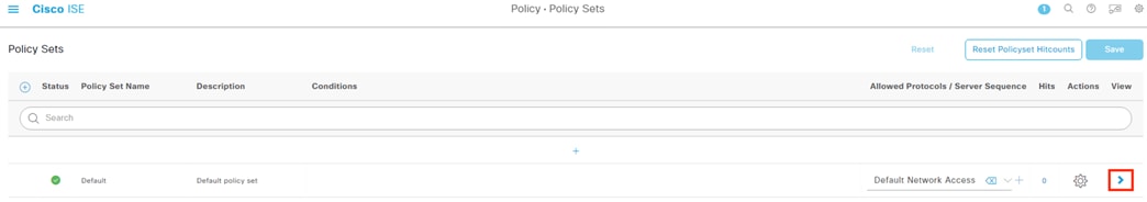
Step 2. The ANC policies can be added to either the Authorization Policy Local or Global exceptions. This guide uses the Global example. Click the > icon to expand Global Exceptions, then click the + button to add a new rule.
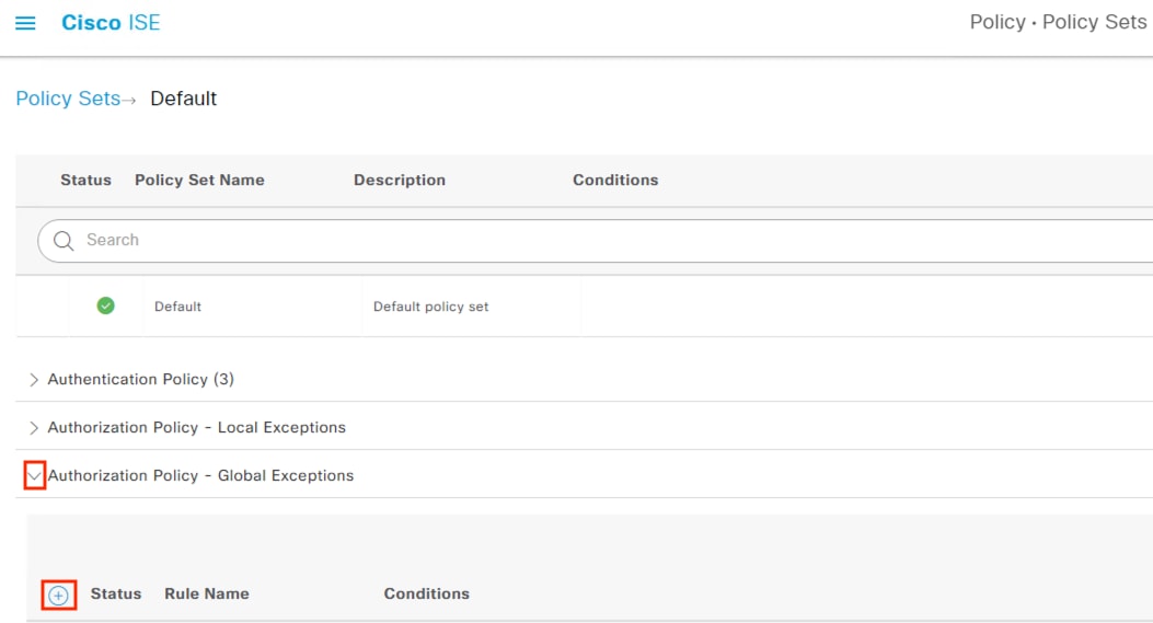
Step 3. Give the rule a name (once again, Quarantine is recommended) and then click the + icon in the middle of the rule to open the Conditions Studio.
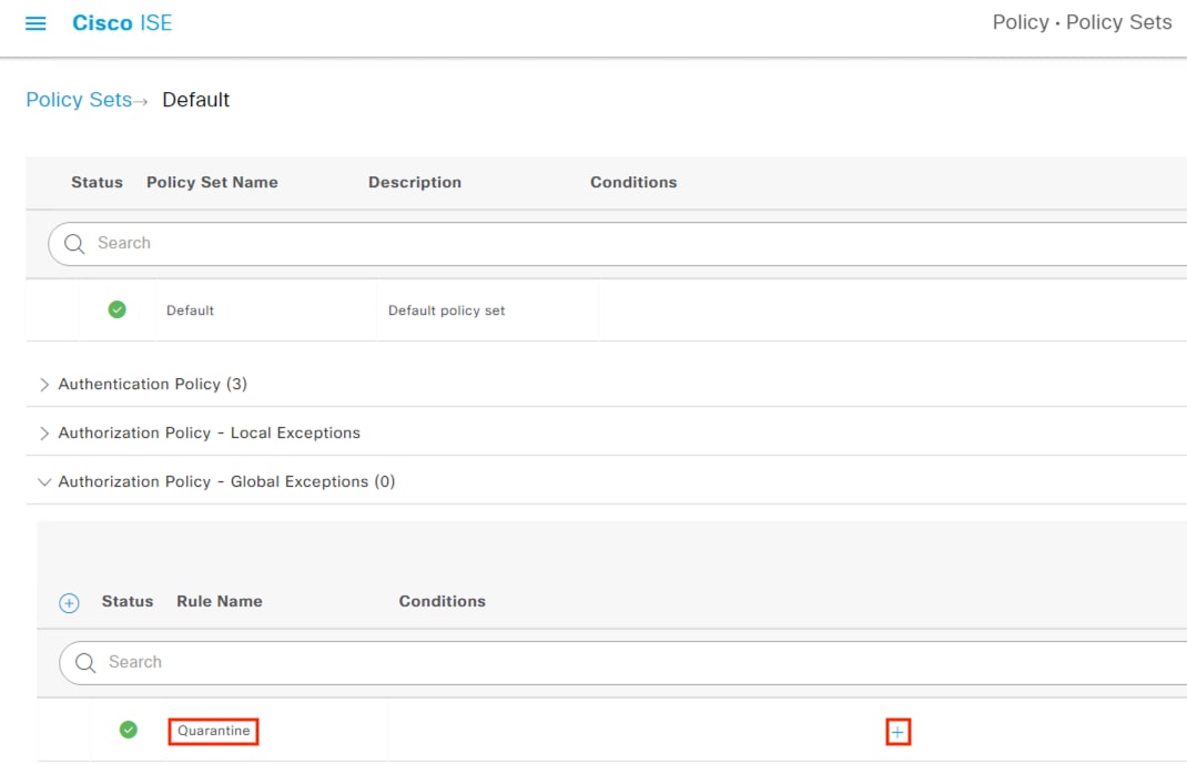
Step 4. Click the top line that has the text ‘Click to add an attribute’. Search ‘anc’ in the Attribute Column and click on ANCPolicy.
![]()
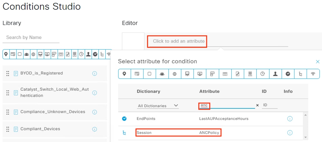
Step 5. Leave the first value as Equals, click the second dropdown arrow, and select Quarantine. Click the Use button.
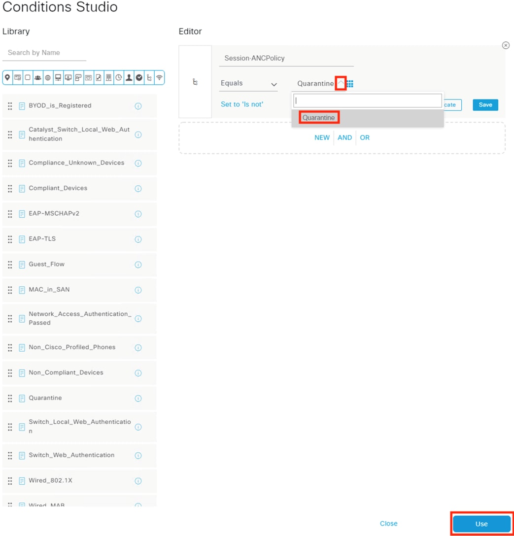
Step 6. Finally, click the dropdown under Profiles and associate the Quarantine action with the DenyAccess profile. Note: some deployments may prefer not to deny all access with the Quarantine action. If that is the case, the profile can be set to PermitAccess (or another profile) and a Quarantine SGT assigned. Click Save.
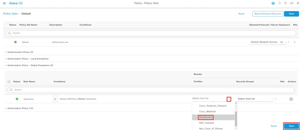
Netflow serves as a monitoring backbone for network traffic. A well-designed Netflow architecture can provide data on the origination and termination of every network connection, along with capturing data at intermediary points in the traffic path. This connection data can be used both for connectivity troubleshooting and Secure Analytics. In this guide we’ll aggregate Netflow logs from a switch and firewall into the Cisco Telemetry Broker, then send Netflow data from CTB to Secure Network Analytics for heuristic security analysis.
This guide demonstrates Netflow configuration for the Secure Firewall and Catalyst 9300 platforms.
Step 1. From the GUI, navigate to Configuration à Services à Netflow.
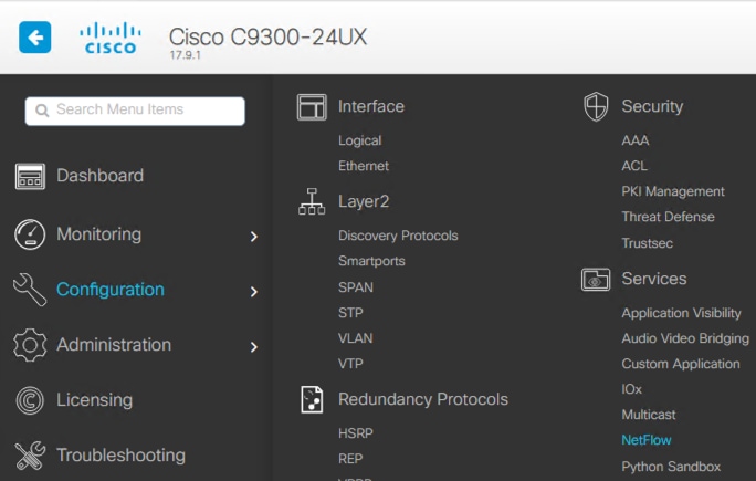
Step 2. Click the Add button.
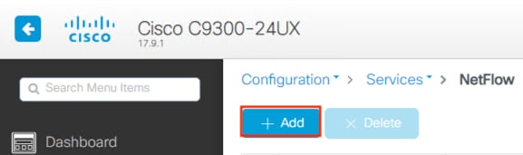
Step 3. Since we intend to use this Netflow for Secure Analytics, we’ll use the StealthWatch Netflow Template. Enter the IP of the Telemetry Broker Node’s telemetry interface (the CTB node has two interfaces, one for management and one to receive telemetry data), the standard Netflow port of 2055, specify an Export Interface for the switch, and select a Sampling Method. For this example we’re using Full Netflow, but we could change this to Deterministic or Random for a heavily utilized switch. Select all interfaces for which Netflow should be collected and click Apply to Device.
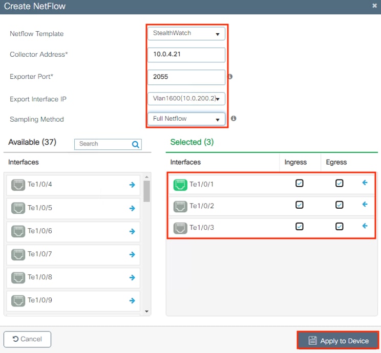
Step 4. Confirm the details for the new Netflow config.
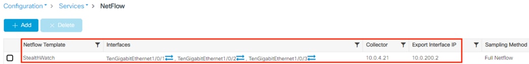
Step 5. To review or save the added running-config, click the Save Configuration icon.

Step 6. Click the Show Diff button to review configuration changes made since the last time running-config was copied to startup.
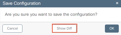
Step 7. Scroll down and review config additions listed in green.
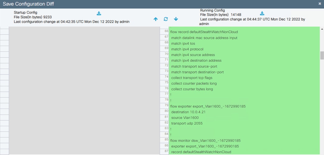
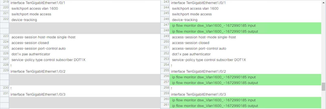
Step 8. When satisfied, click Apply to Device to copy the running-config to startup-config.
Secure Firewall: Configure Netflow
Step 1. Navigate to Objects à Object Management.
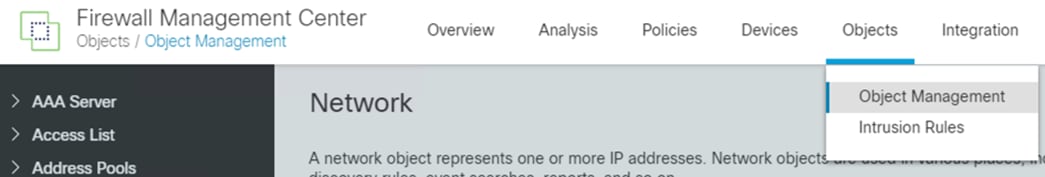
Step 2. Select FlexConfig à Text Objects from the left menu.
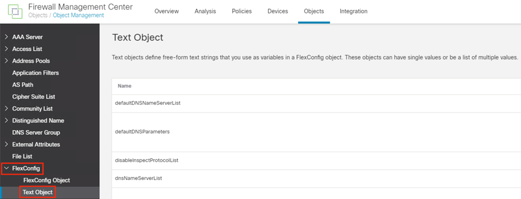
Step 3. Enter the word ‘netflow’ in the search bar and click the pencil icon to edit the netflow_Destination object.
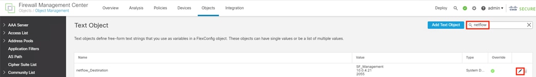
Step 4. Set the count to 3, specify the interface that will send Netflow data, and set the IP address and port for the Netflow collector. In this example, Netflow is sent from a data interface for a management network to the Cisco Telemetry Broker node telemetry interface over the default Netflow port of 2055. Click Save.
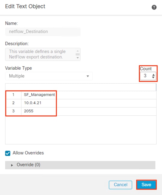
Step 5. Navigate to Devices à FlexConfig.
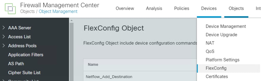
Step 6. Click the New Policy button in the upper right.
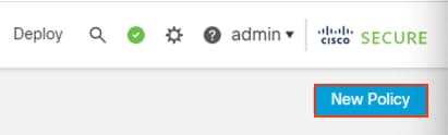
Step 7. Set a name and add the target device to the policy. Click Save
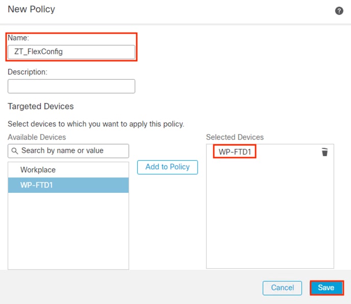
Step 8. From the left side menu, select Netflow_Add_Destination and Netflow_Set_Parameters, then use the > button to append them to the FlexConfig.
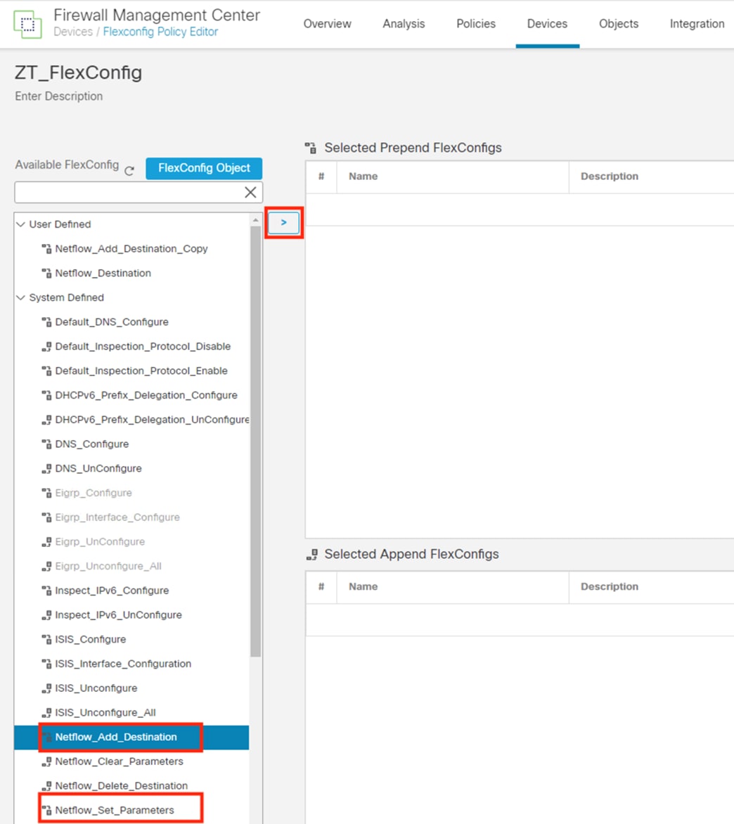
Step 9. Click Save, then Deploy.
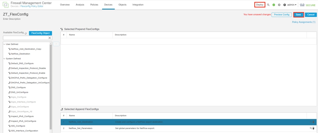
Step 10. Click to deploy changes.

Step 11. A validation warning appears when deploying a FlexConfig policy. Click on it to review the message.
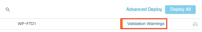
Step 12. Review the message about FlexConfig validation, then click Proceed with Deploy when ready.
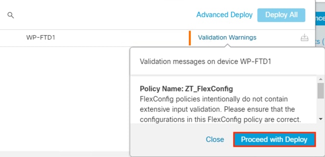
Step 13. Confirm successful deployment.
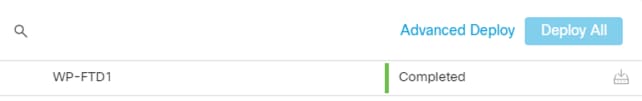
Step 14. Flex Config is intended as a one-time change, and the Flex Config objects should be removed from the Flex Config policy after they are applied. This will also free up generic objects to be modified and applied to other firewalls, as needed. Return to the Flex Config policy and click the trash icons to remove the Netflow_Add_Destination and Netflow_Set_Parameters objects.
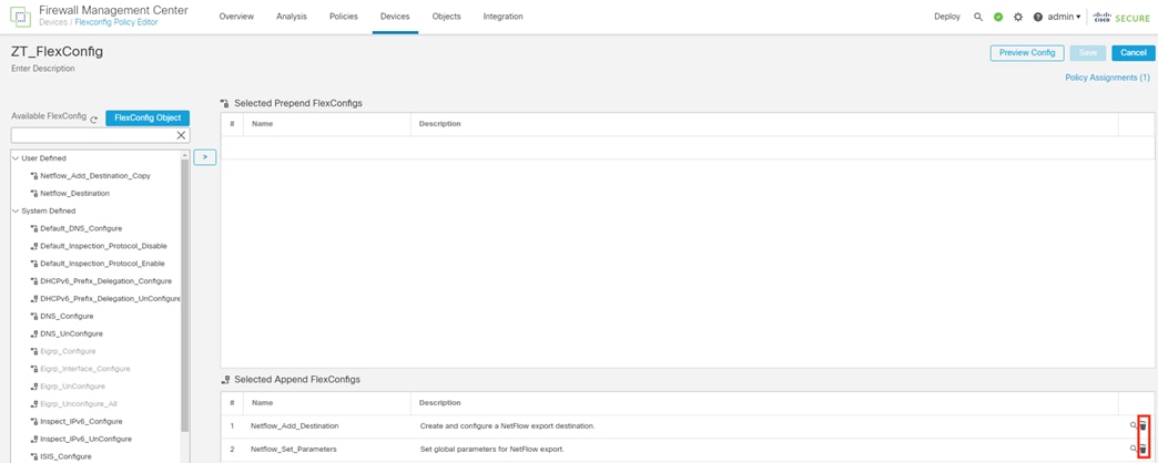
Note: This does not overwrite the previously applied configuration.
Step 15. Click Save, then Deploy the changes again.
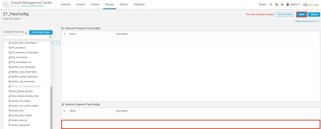
Note: If there is ever a need to clear the applied Flex Config objects, use the Netflow_Clear_Parameters and Netflow_Delete_Destination objects on the left side menu.
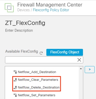
CTB Manager: Verify Netflow Sources
In the prior sections, the Secure Firewall and Catalyst switch were configured to send Netflow data to the CTB Node telemetry interface. These flows can be verified from the Sources tab of the CTB Manager.
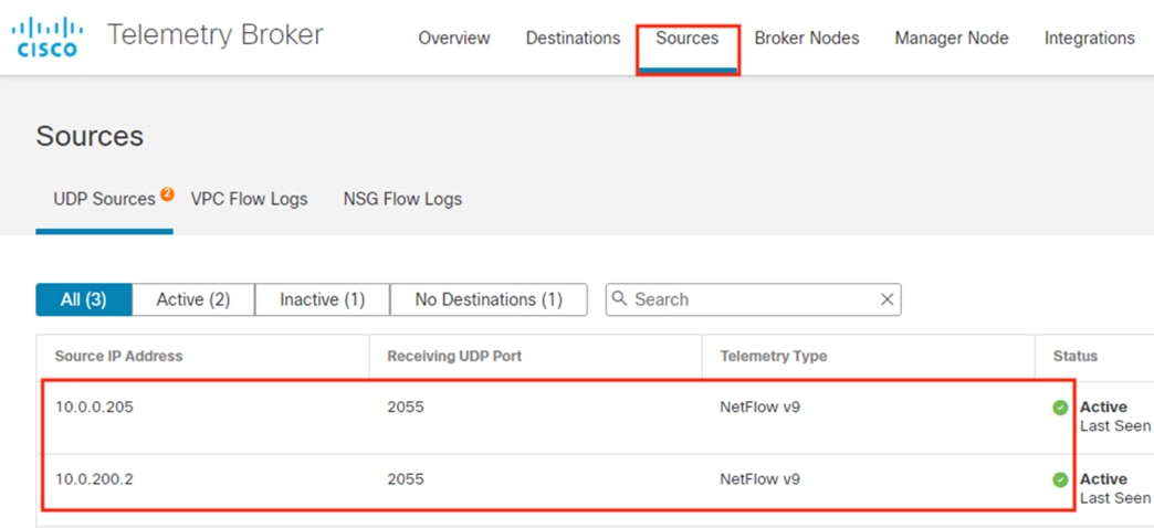
Confirm all configured Netflow sources have the green check mark and show Active status in the CTB Manager, then continue to the next section.
CTB Manager: Configure Netflow Destinations
CTB is now aggregating Netflow data from two devices. The first destination for that Netflow will be the Secure Network Analytics Netflow Collector.
Step 1. In the CTB Manager GUI, navigate to Destinations, click the Add Destination button, and select UDP Destination.
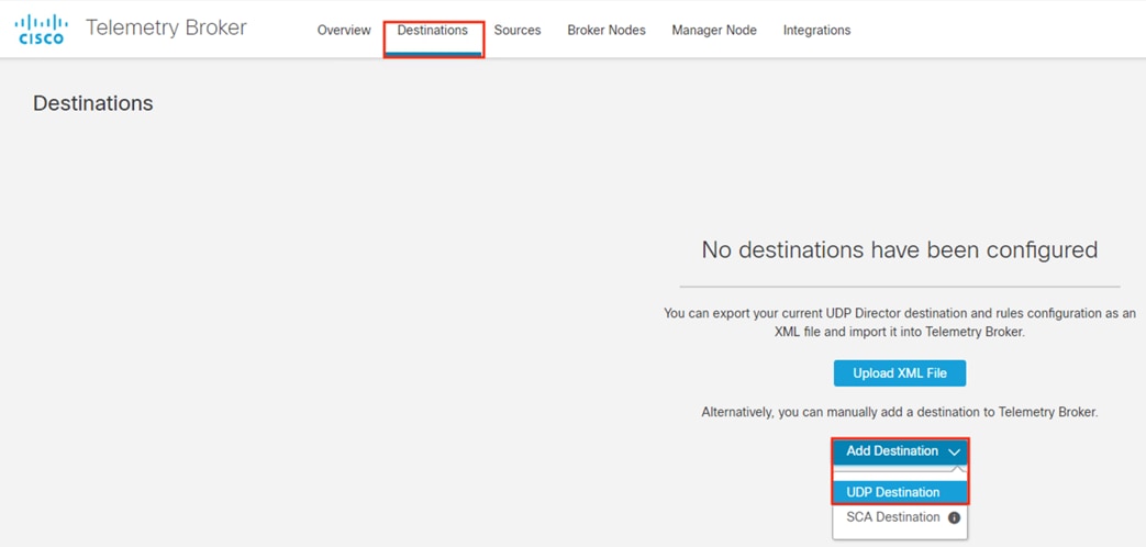
Step 2. Enter a name for the Netflow destination, set the IP for the Secure Analytics Flow Collector, and set the default Netflow port of 2055. Leave the option to Check Destination Reachability checked so that CTB can verify that the destination is reachable. Click Save.
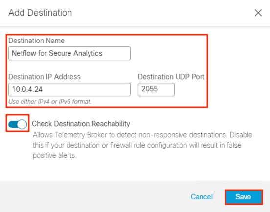
Step 3. With the Netflow destination added, we need to configure a rule that specifies what source logs will be fed to that destination. First, verify that CTB can reach the Netflow destination by confirming the green Reachable box highlighted below. If the destination is reachable, click on Add Rule.
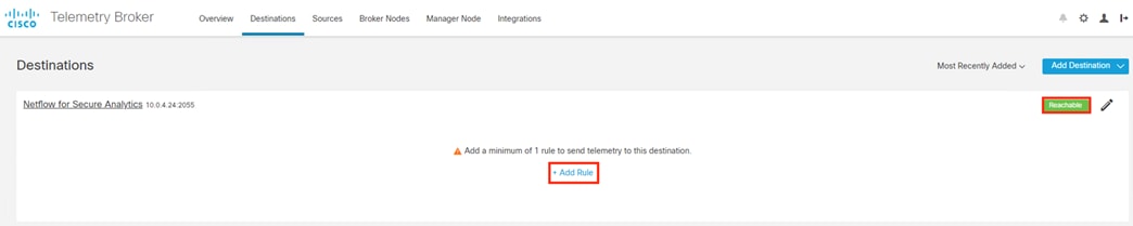
Step 4. Set the receiving port to the Netflow default of 2055. For the ‘Include sources in these subnets’ field, enter subnets that include the hosts that are sending Netflow data to the CTB (in this example, the Secure Firewall and Catalyst switch). The subnets specified can either be broad to capture an entire network site or limited to specific hosts. Click Save.
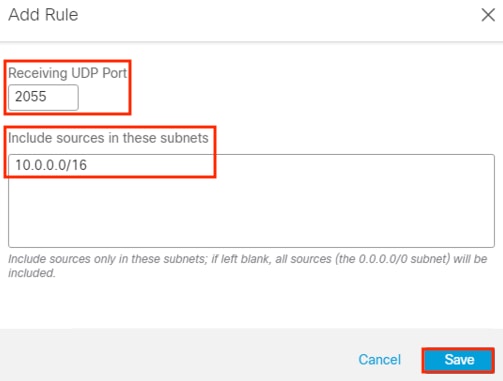
We now have a created destination and rule.
Note: The destination IP and port is listed in the top left (the Secure Analytics Flow Collector), and the rule for Netflow sources is in the lower left (this also shows the number of sources that are matching the rule, the switch and firewall).
Step 5. Confirm that the Sent Rate (the blue line) begins populating after the rule is created.
![]()
![]()
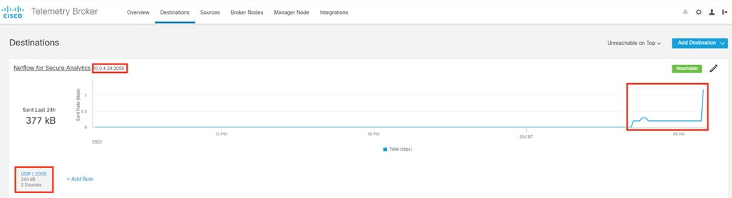
Secure Analytics: Validate Flow Data
In the last section, the CTB shows that the Secure Analytics Flow Collector is reachable, and that flow data is being sent.
Step 1. To confirm that flow data is being received, connect to the Secure Analytics Manager, and navigate to Dashboards à Network Security.
The Network Security page has a Flow Collection Trend chart that will display flows per second.
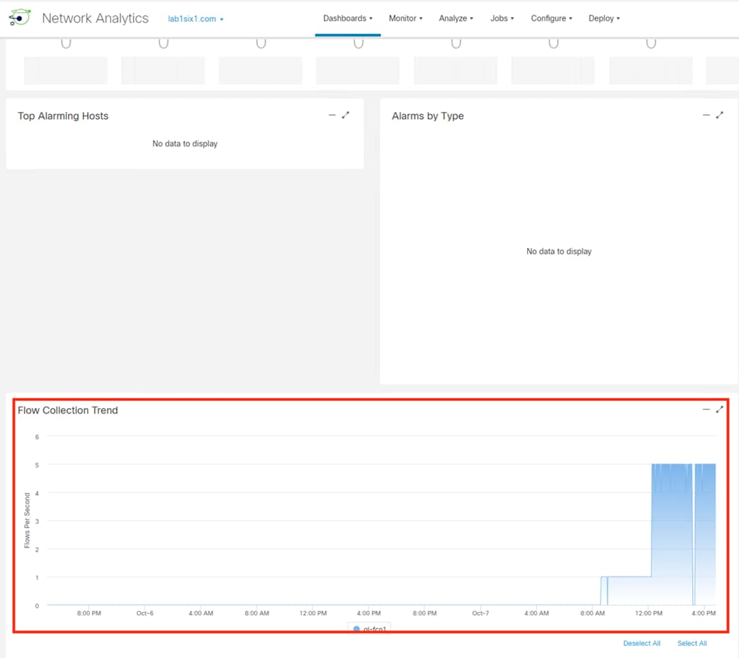
Step 2. Confirm that flows per second are > 0.
ISE: Create TrustSec AAA Server
Step 1. Click the Menu icon (![]() ) and navigate to Work Centers à TrustSec à Components.
) and navigate to Work Centers à TrustSec à Components.
Step 2. Expand the Trustsec Servers dropdown arrow, then click on Trustsec AAA Servers.
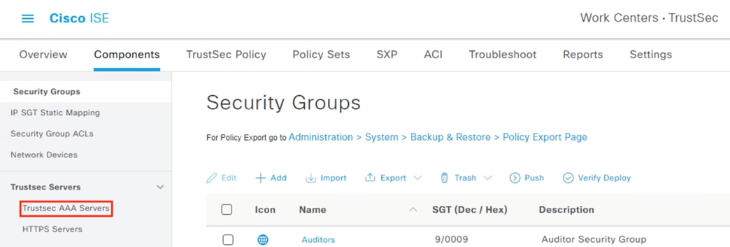
Step 3. Click on an existing AAA server to confirm details or click the Add button to create one.
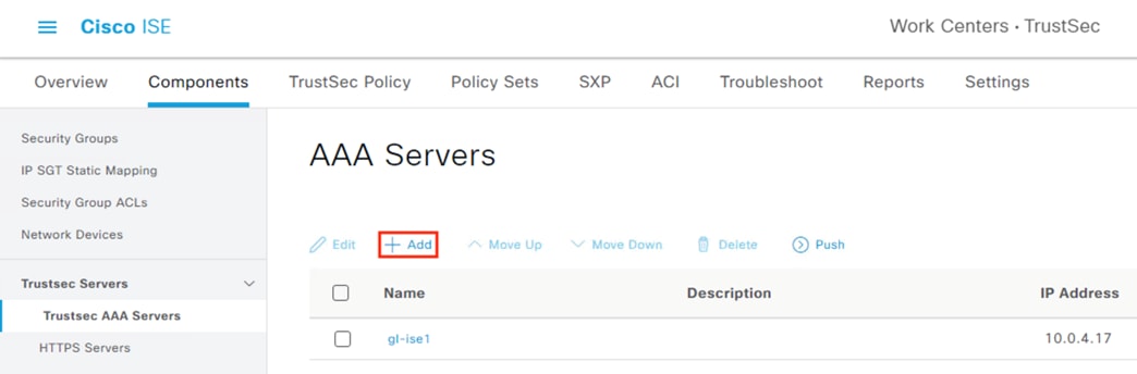
Step 4. Set a name, specify the IP of the ISE node that will serve as the TrustSec AAA server (this will probably be the primary node, and some deployments will want to configure multiple nodes), set the port to 1812, then click Save.
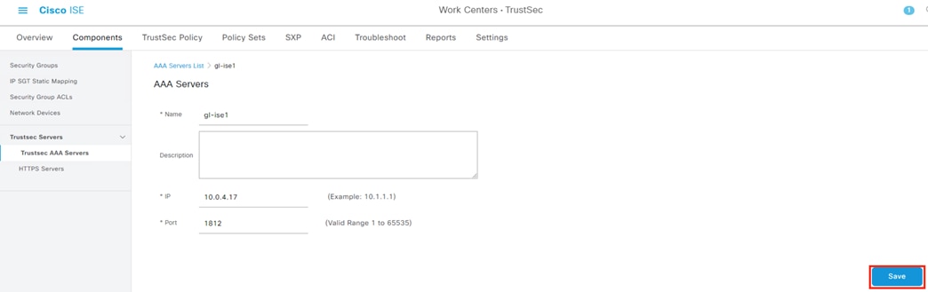
ISE: Add Switches as Network Devices
Step 1. Click the Menu icon (![]() ) and navigate to Administration à Network Resources à Network Devices.
) and navigate to Administration à Network Resources à Network Devices.
Step 2. Click the Add button (or select an existing switch and click Edit).
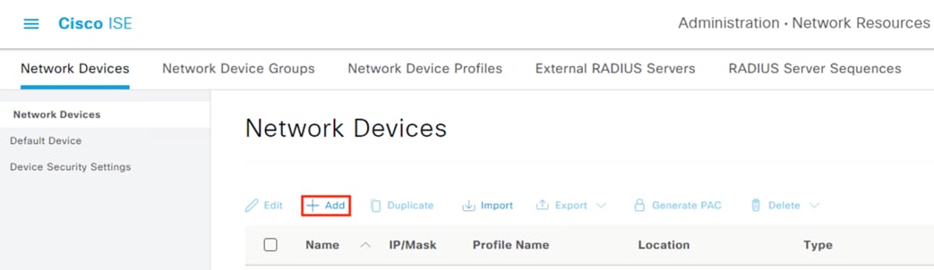
Step 3. Enter a name, set the IP address of the interface or VLAN that will connect to Cisco ISE, select Cisco as the Device Profile, set model and software information if desired, and set Location, IPSEC, and Device Type values.
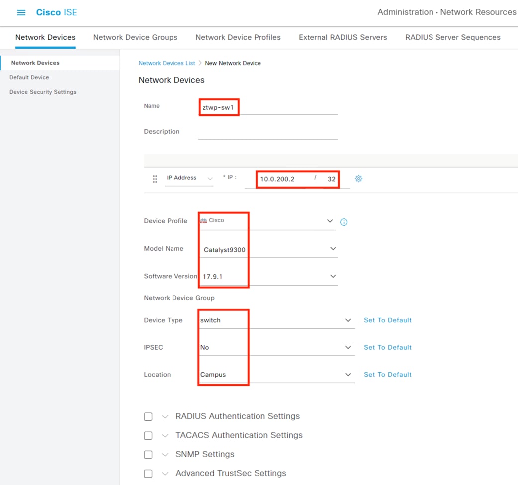
Note: New locations and device types can be created by clicking the dropdown arrows and then clicking the gear icon, as shown below.
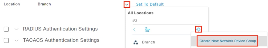
Step 4. Check the box for RADIUS Authentication Settings and expand the dropdown arrow.
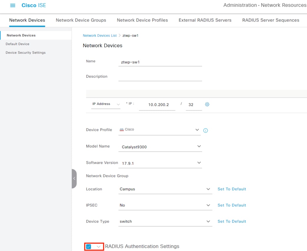
Step 5. Enter a Shared Secret and record it for later use, as it will be needed for the switch side configuration. Leave the CoA Port with the default value of 1700. DTLS can be configured for additional security if desired, and KeyWrap should be used for FIPS deployments.
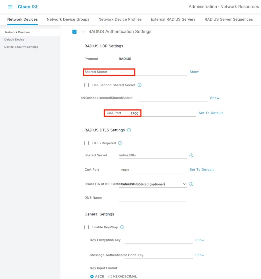
Step 6. Collapse the RADIUS dropdown and check the box next to Advanced TrustSec Settings, then click the dropdown arrow to expand the settings.
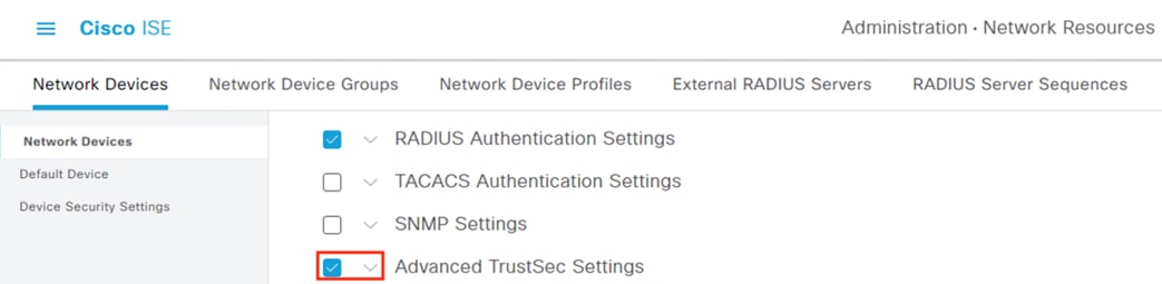
Step 7. Check the box for “Use Device ID for TrustSec Identification”, set a Device ID (the example below uses the Device Name), and create a password for the device authentication to ISE. Again, record the password for the later switch configuration.
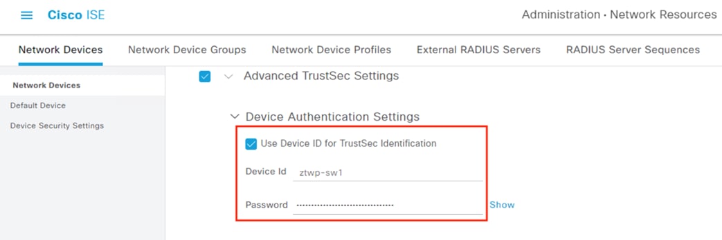
Step 8. Scroll down and check the box for ‘Other TrustSec devices to trust this device’. Also check the box for ‘Send configuration changes to device’ and select the radio button for CoA.
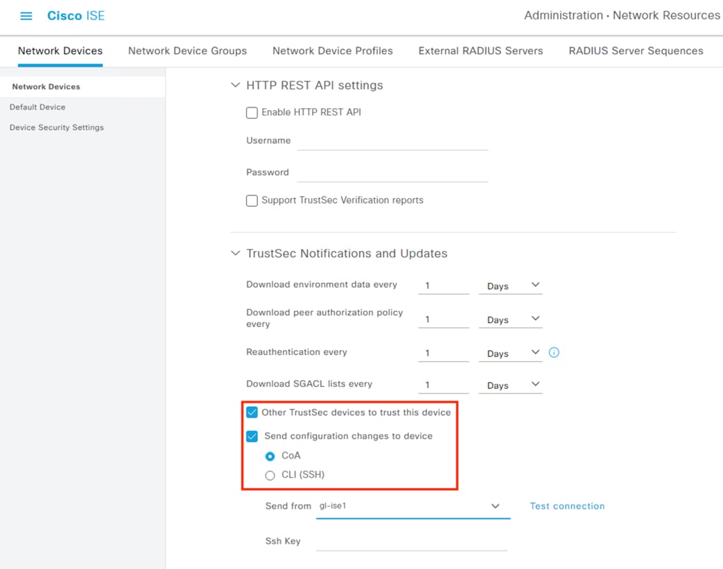
Step 9. Scroll further down and check the box for ‘Include this device when deploying Security Group Tag Mapping Updates’. Set an EXEC Mode username and password that can access the switch, then click Submit.
Note: It is recommended to use a service account for this connection in production networks.
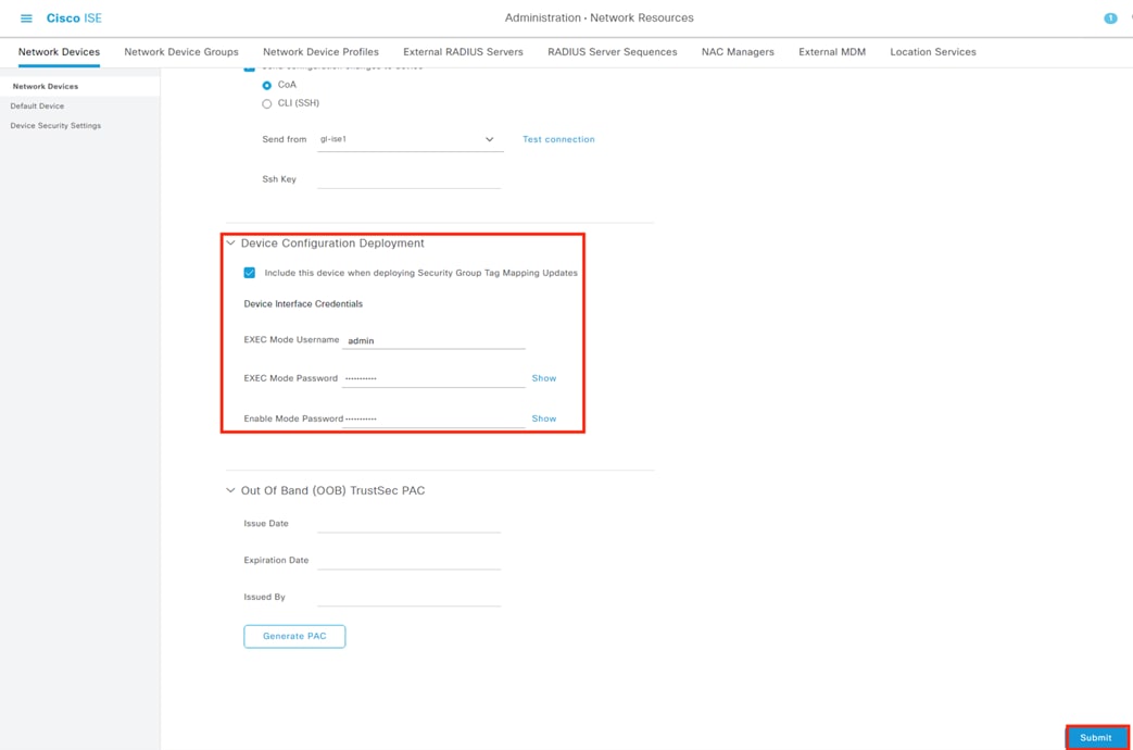
Step 10. Confirm the new entry populates.
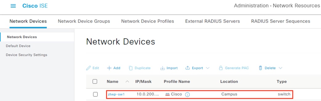
Step 11. Repeat the above steps to add additional switches.
ISE: Assign TrustSec Switches to TrustSec Security Group
Step 1. Click the Menu icon (![]() ) and navigate to Work Centers à TrustSec à TrustSec Policy.
) and navigate to Work Centers à TrustSec à TrustSec Policy.
Step 2. Click on Network Device Authorization.
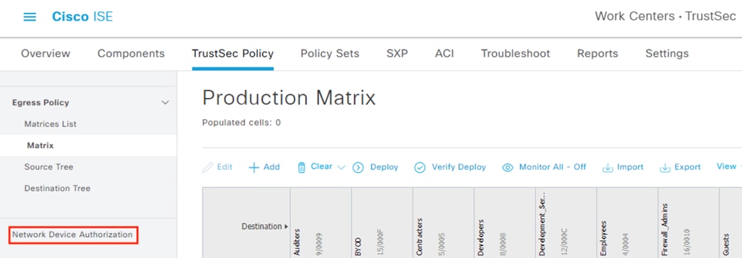
Step 3. On the Default Rule, click the dropdown arrow near Edit and select ‘Insert new row above’.
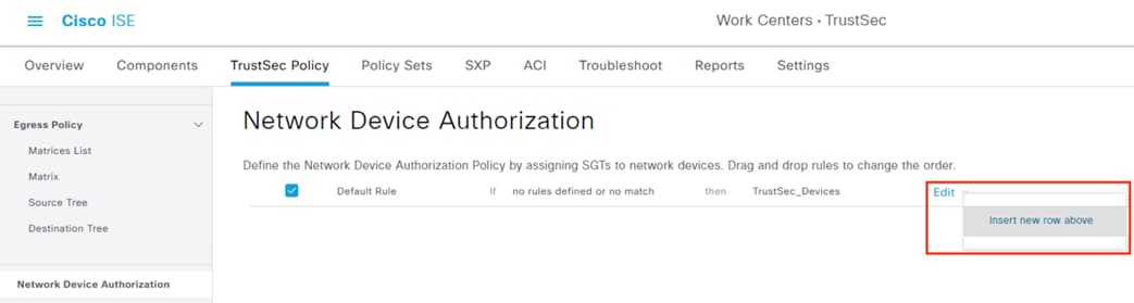
Step 4. Set the Security Group to TrustSec_Devices, change the name if desired, click the dropdown arrow under Conditions and select Create New Condition.
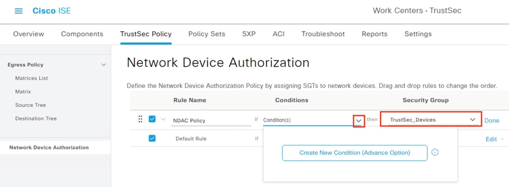
Step 5. Set the Condition to Device Type, leave the Expression on Equals, and select the switch device type configured previously.
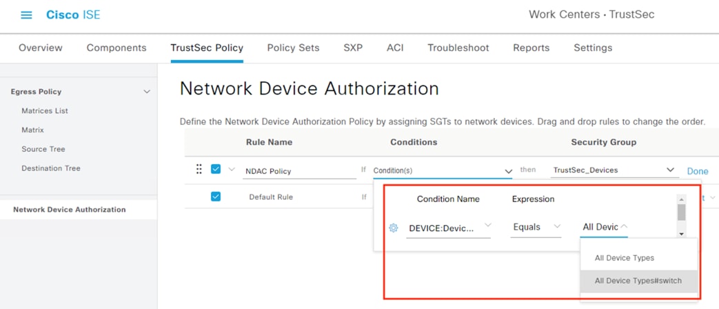
Note: In this example all devices of type switch are added to the TrustSec_Devices Security Group.
Step 6. Additional criteria can be set as needed by clicking the gear icon and selecting ‘Add Attribute/Value’ to create another condition.
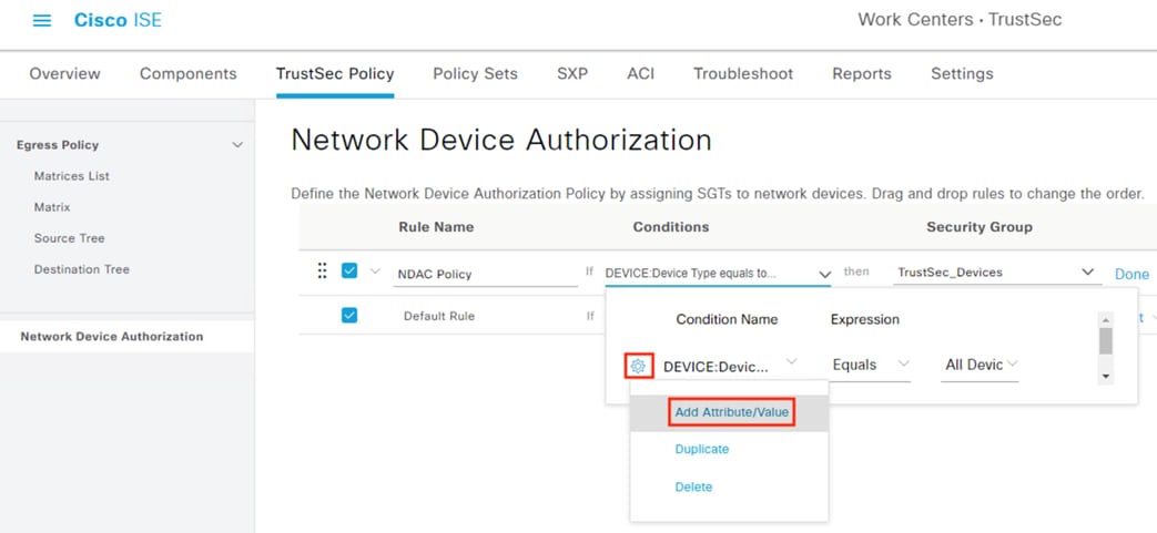
Step 7. Click the main page to collapse the Condition window. If the Default rule is set to the TrustSec_Devices Security Group, set the rule to Unknown. Click Save.
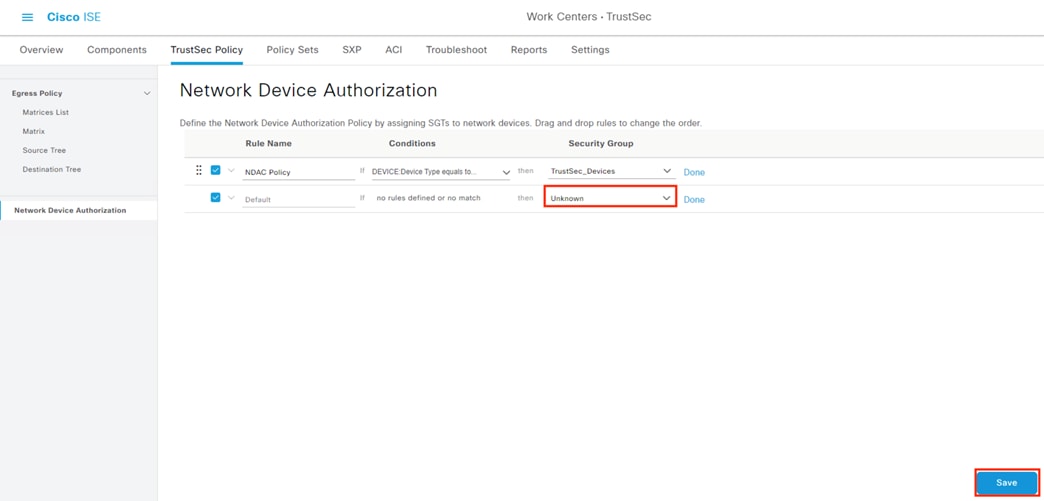
ISE: Disable Protected Access Credential (PAC) (Optional)
PAC provisioning can fail and remain in a hung state if an invalid device ID is provided. As a workaround to this failure point, the PAC feature can be disabled. See ‘Restrictions for Cisco TrustSec’ in the Cisco TrustSec Configuration Guide.
Step 1. Click the Menu icon (![]() ) and navigate to Administration à System à Settings.
) and navigate to Administration à System à Settings.
Step 2. On the left side menu, click the dropdown for Protocols, click the dropdown for EAP-FAST, and click EAP FAST Settings.
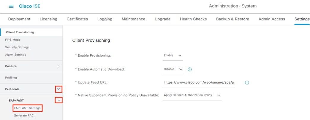
Step 3. If desired, set a recognizable value for the Authority Identity Info Description, tick the box for ‘Enable PAC-less Session Resume’, then click Save.
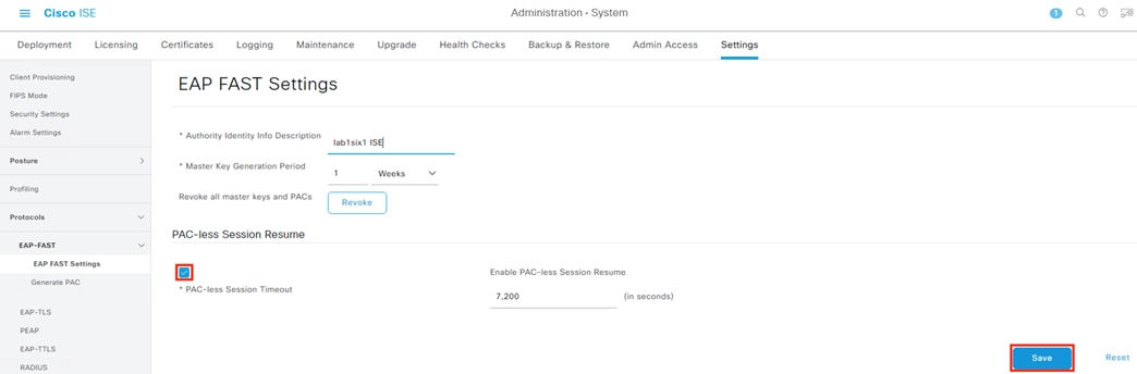
Note: This section will configure the switch to authenticate via AAA, which can change the local auth configuration on the switch for CLI access. It is recommended to save configuration and open an SSH session before starting this configuration from the GUI. Optional steps for re-enabling local CLI access are provided at the end of this section.
Step 1. Navigate to Configuration à Security à AAA.
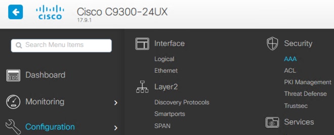
Step 2. Click the AAA Wizard button.
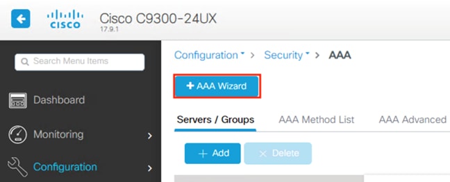
Step 3. Populate the ISE server details and tick the box for PAC Key. Enter the PAC Key and CoA Server Keys (these must both match the key configured for the switch in ISE under Administration à Network Resources à Network Devices à Add/Edit Device à RADIUS Authentication Settings à Shared Secret in the ISE: Add Switches as Network Devices section). Ensure RADIUS is checked in the upper left and Support for CoA is enabled. Click Next.
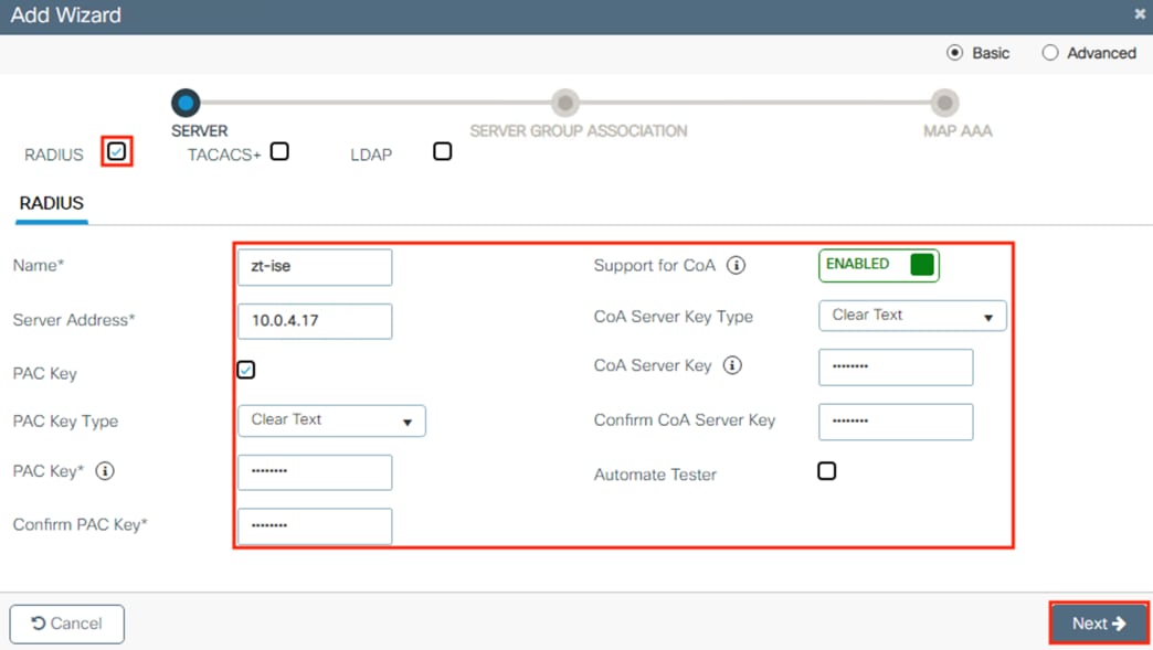
Step 4. Enter a name for the RADIUS group and add the RADIUS server configured on the prior page to the Assigned Servers box. Click Next.
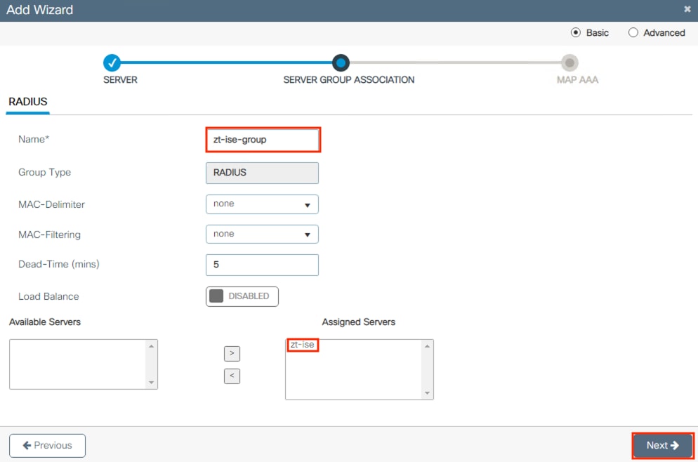
Step 5. We’ll now create a series of mappings for the RADIUS server. From the Authentication tab, set the Type to dot1x and add the group created on the prior page to the Assigned Server Groups box. Note: do not click Apply to Device until all three AAA sections are completed.
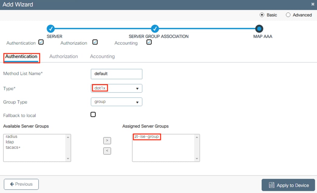
Step 6. Click the Authorization tab, set the Type to network, and add the zt-ise-group to Assigned Server Groups.
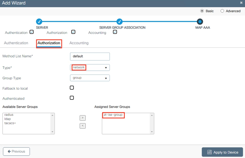
Step 7. Click the Accounting tab, select identity as the Type, set the zt-ise-group to the Assigned Server Groups, enter a name, and click Apply to Device.
![]()
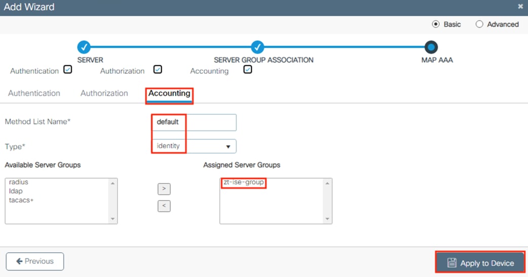
Step 8. The configuration changes can be confirmed by clicking on the save icon in the top right and then the Show Diff button.

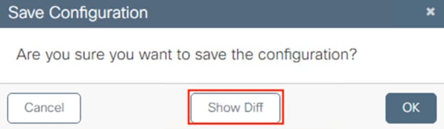
The above configuration adds the following lines to running-config.
AAA configuration is replaced.
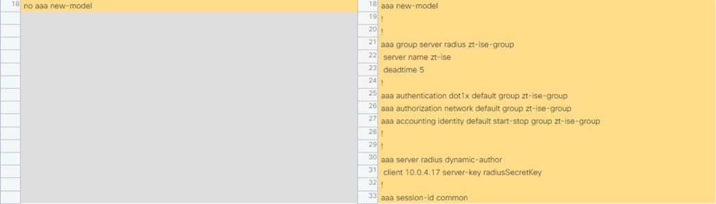
RADIUS server is configured, and PAC key is set.

Local login is disabled.
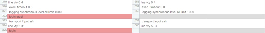
Below are notes on the functionality of each command.
aaa new-model – Create a new AAA instance.
aaa group server radius zt-ise-group – Create a group of RADIUS servers.
server name zt-ise – Assign a previously created RADIUS server to the group.
deadtime 5 – marks the RADIUS server as dead if 5 minutes pass without communication from the RADIUS server.
aaa authentication dot1x default group zt-ise-group – Assigns the created zt-ise-group as the authentication method for 802.1X ports.
aaa authorization network default group zt-ise-group – Specifies the authorization RADIUS server group for all network related service requests.
aaa accounting identity default start-stop group zt-ise-group – Configures the switch to send AAA Accounting logs to the configured RADIUS group when an 802.1X session begins or ends.
radius server zt-ise – Create a new RADIUS server.
address ipv4 10.0.4.17 auth-port 1812 acct-port 1813 – Specifies the IP address of the RADIUS server and port numbers for Authorization and Accounting.
pac key Admin123 – Sets the PAC key used to retrieve the PAC from the RADIUS server.
Below are the commands in a format that can be pasted into the CLI:
conf t
aaa new-model
radius server zt-ise
address ipv4 10.0.4.17 auth-port 1812 acct-port 1813
pac key radiusSecretKey
exit
aaa group server radius zt-ise-group
server name zt-ise
exit
aaa server radius dynamic-author
client 10.0.4.17 server-key radiusSecretKey
exit
aaa authentication dot1x default group zt-ise-group
aaa authorization network default group zt-ise-group
aaa accounting identity default start-stop group zt-ise-group
end
Switch: Configure Local Authentication (Optional)
The configuration in the prior section set up AAA, which automatically disables local authentication on the VTY lines. This section can optionally be used to re-enable local CLI access after configuring AAA.
Note: In a production environment it is preferable that all CLI access use TACACS, with static credentials being reserved for break-glass scenarios.
Step 1. From the switch GUI, navigate to Configuration à Security à AAA.
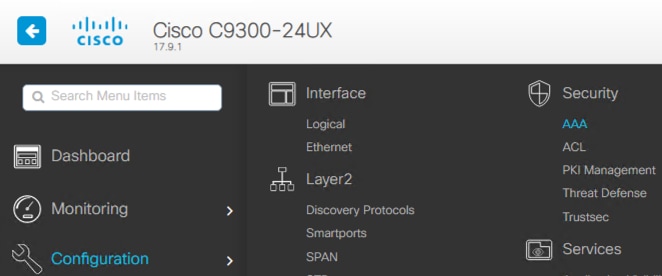
Step 2. Click on AAA Method List, select Authorization, then click the Add button.
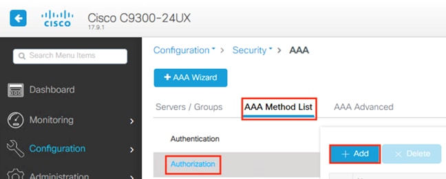
Step 3. Leave the name as default, set Type to exec, set Group Type to local, and click the Apply to Device button.
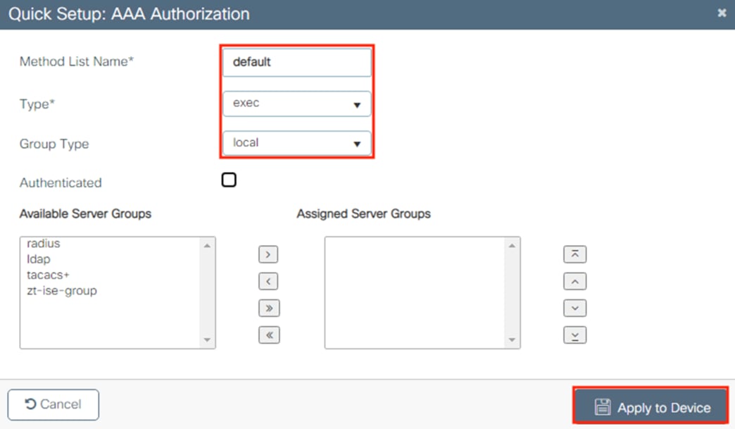
The above configuration adds the following config to running-config.
![]()
The above in text form.
aaa authorization exec default local
Step 4. Use an SSH client to test a known local account and verify access.
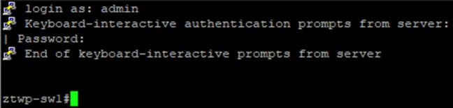
Step 1. Navigate to Configuration à Security à Trustsec.
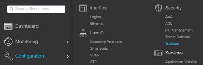
Step 2. Click Modify next to CTS Credentials.
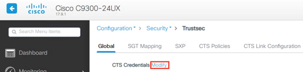
Step 3. Enter the CTS Device ID and the password from the Device Authentication Settings configured previously in ISE [under Administration à Network Resources à Network Devices à Add/edit device à Advanced TrustSec Settings à Device Authentication Settings (as covered in the ISE: Add Switches as Network Devices section)]. Click Apply.
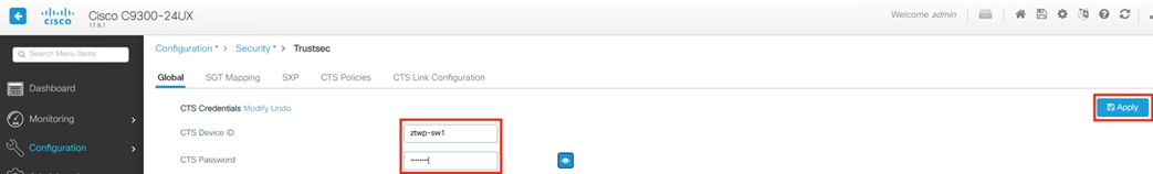
Step 4. Click on Add AAA Method List.
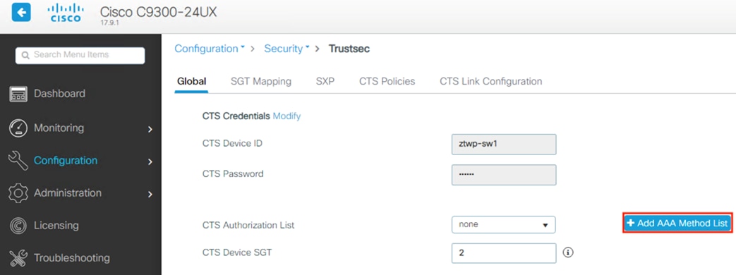
Step 5. Give the RADIUS server a name, enter the IP address of the ISE node, and create names for the RADIUS Server Group and Method List Name. For the PAC Key, enter the RADIUS Shared Secret configured previously in ISE under Administration à Network Resources à Network Devices à Add device à RADIUS Authentication Settings à Shared Secret. Click Apply to Device.
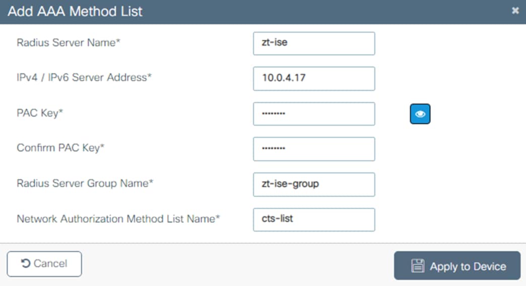
Step 6. The list name configured in the prior step will now populate in the CTS Authorization List dropdown. Click Apply.
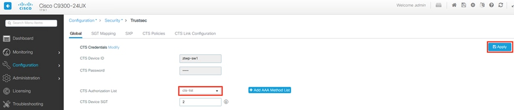
Step 7. Click the floppy disk icon in the top right to review the applied configuration.
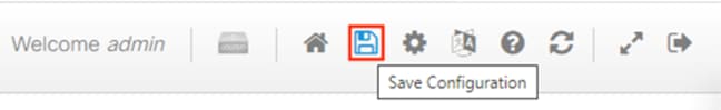
Click on Show Diff.

Review the modified running configuration and note that local login configuration may have been removed. It is recommended to verify successful SSH authentication before saving the config to startup.
AAA auth object cts-list is added under the AAA config.
![]()
The cts-list is defined.
![]()
Below is the applied configuration in text form:
aaa authorization network cts-list group zt-ise-group
cts authorization list cts-list
Switch and ISE: Verifying Successful TrustSec Connection
The configuration in the prior section will cause the switch to initiate a connection to ISE for TrustSec authentication. Successful authentication can be verified via the CLI or ISE logs.
Step 1. From the switch CLI, run the following command:
# show cts pacs
If the switch to ISE connection was successful, then the PAC will be displayed.
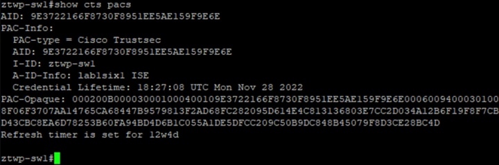
Step 2. In addition to the PAC, also verify the CTS environment data via the following command:
# show cts environment-data
The output should show information from ISE, including the Security Group Name Table.
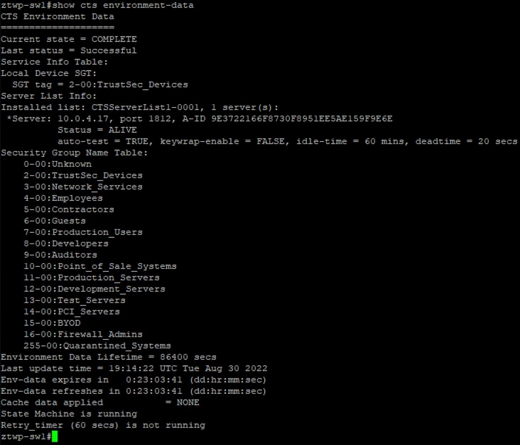
Step 3. If the PAC or environment data is not available on the switch, access the ISE GUI and check the RADIUS Live Logs via Operations à RADIUS à Live Logs.
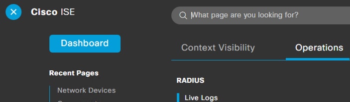
There should be successful authentication logs from the configured switch, as shown below.
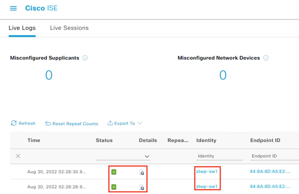
Drilling down on the logs will show that the PAC was successfully provisioned.
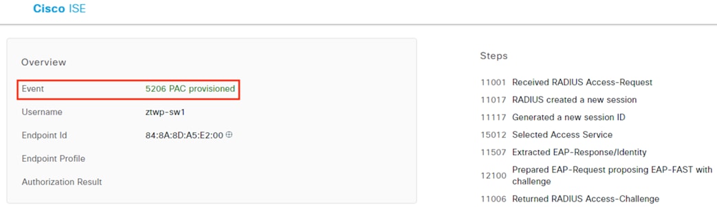
Note: After the switch registers to ISE for TrustSec, ISE will attempt to send a Dynamic Authorization connection to the switch over UDP port 1700. This will fail as shown in the screenshots below until 802.1X is configured on the switch, which we will configure in a later section.
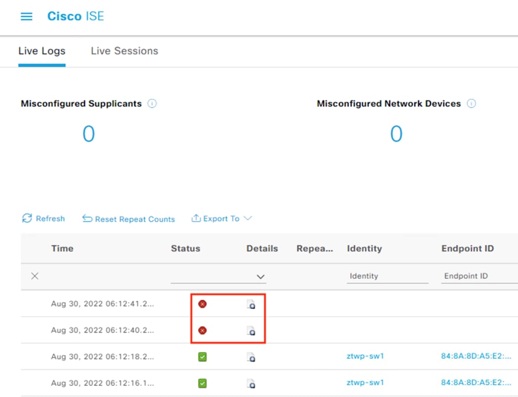
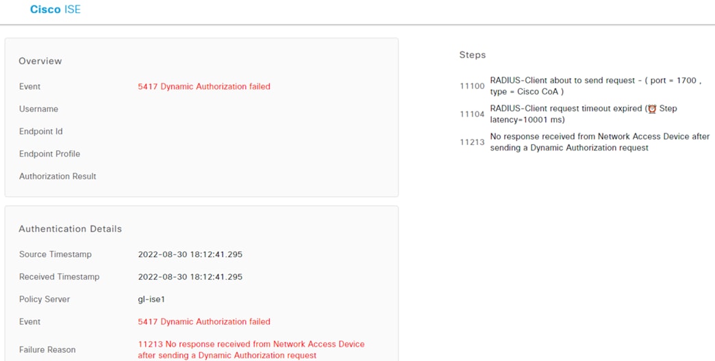
SXP is used to deliver SGT mappings to different areas of the network. SXP can be used to bridge gaps in the network left by devices that are not TrustSec compatible (either for enforcement or passthrough) and can also be used to send specific static SGTs to only the switches that need them for destination SGT enforcement—a must to conserve memory for TrustSec devices in large networks with many IP to SGT maps and SGACLs.
For this guide, SXP is used to deliver static SGT assignments to the Secure Firewall for enforcement. SXP is also used to segment SGACLs into different SGT Domains for the Branch and Data Center switches. In this example, ISE serves the role as speaker for all devices, with the switch and firewall acting as receivers.
ISE: Confirm SXP Service is Enabled
Step 1. Click the Menu icon (![]() ) and navigate to Administration à System à Deployment.
) and navigate to Administration à System à Deployment.
Step 2. Select a node that will be serving as SXP speaker, then click Edit.
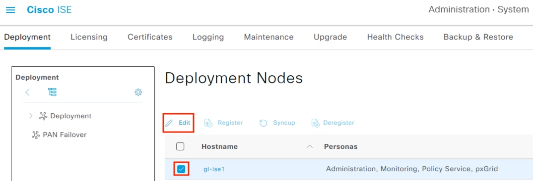
Step 3. Scroll down and confirm that SXP is enabled. If configuration changes are made, click Save in the lower right.
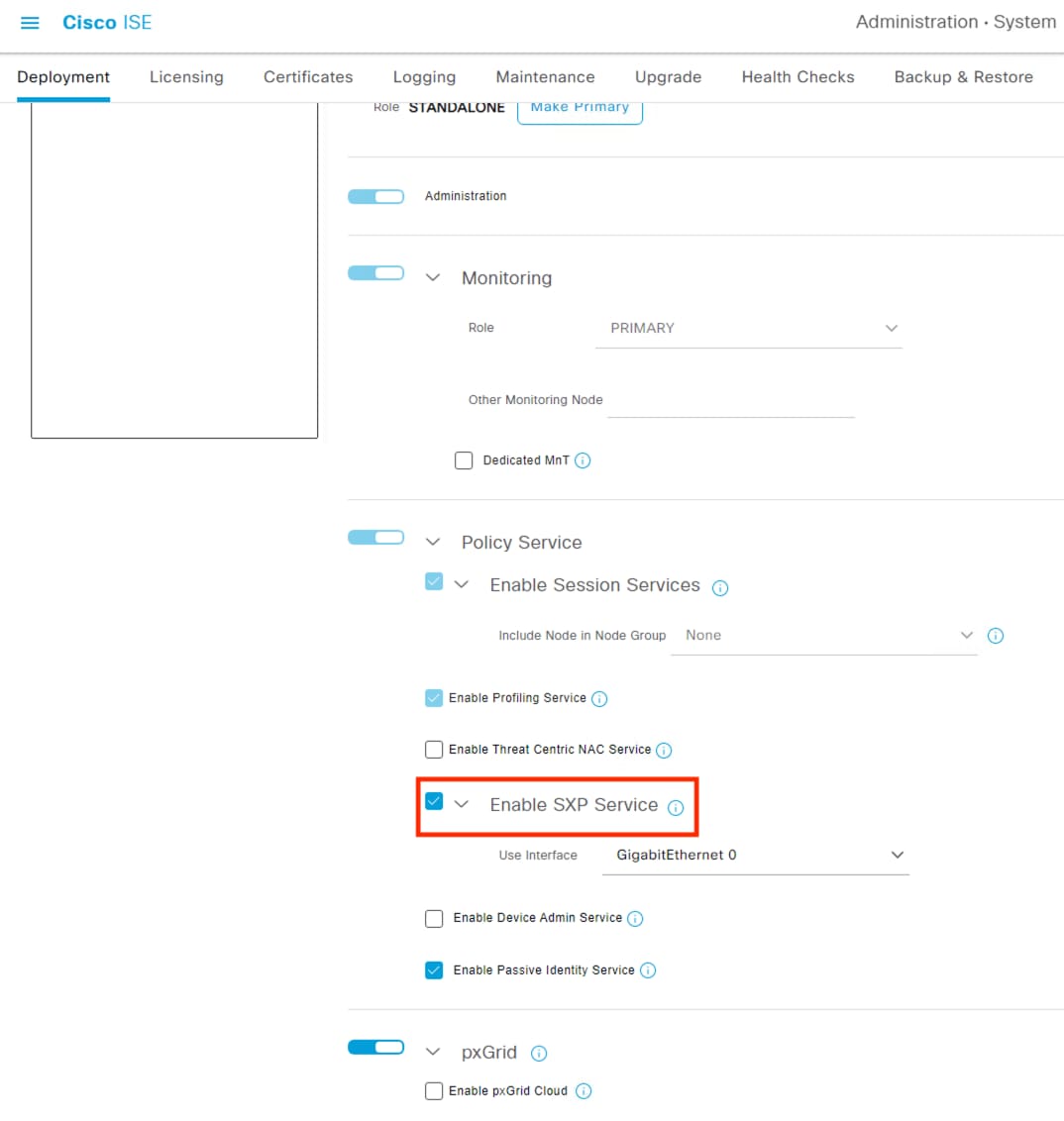
Step 4. Repeat the above steps for any other ISE nodes that will serve as SXP speakers.
Step 1. Click the Menu icon (![]() ) and navigate to Work Centers à TrustSec à Settings.
) and navigate to Work Centers à TrustSec à Settings.
Step 2. Click on SXP Settings.
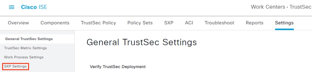
Step 3. Check the box to ‘Publish SXP bindings on PxGrid’, set a global password and record it for the switch configuration in the next section, then click Save.
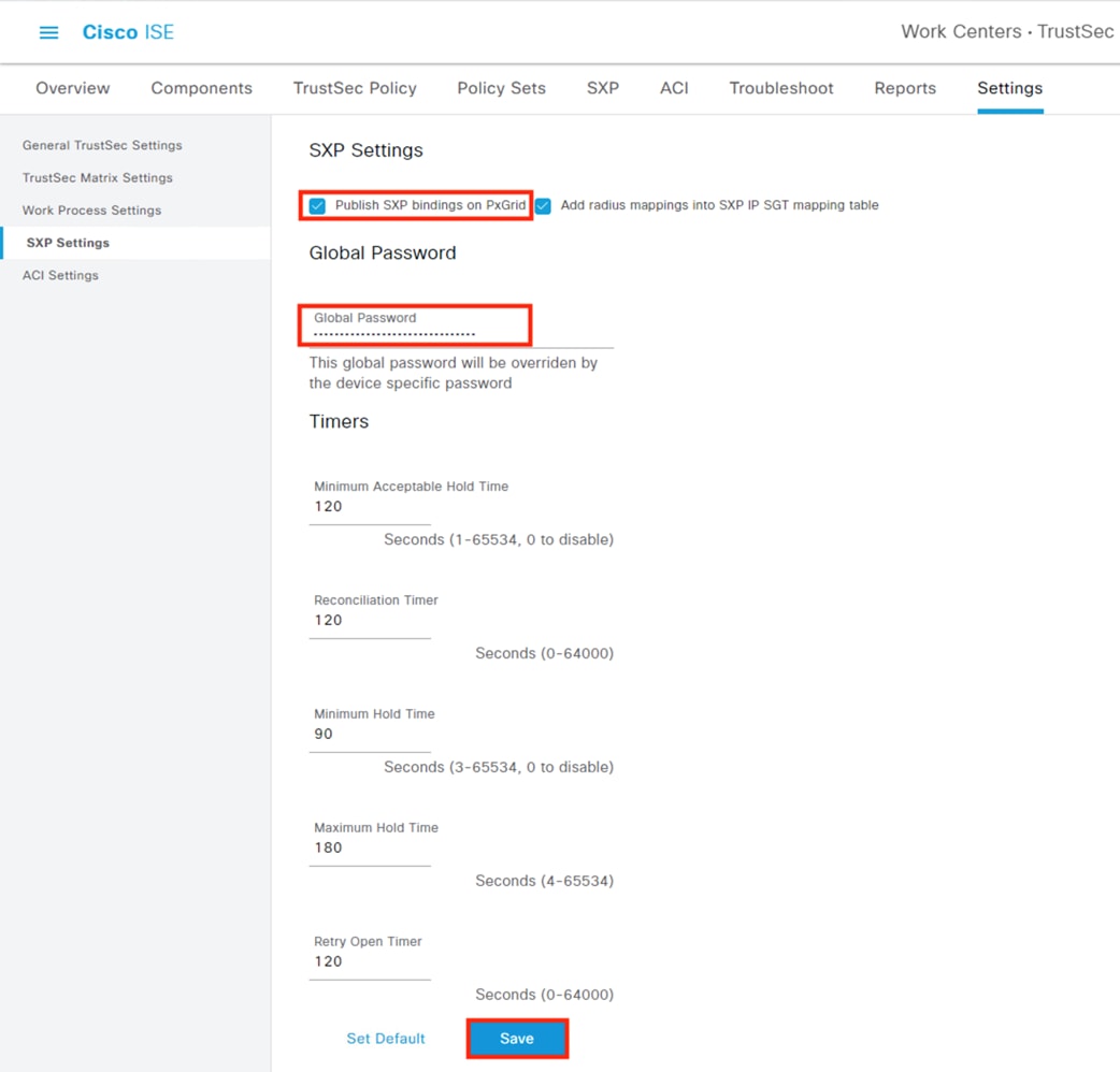
SXP domains are used for two purposes in this design. (1) They serve as a mechanism to push Destination SGT mappings to the FMC managed firewalls across the network. (2) Pushing static SGT mappings to the TrustSec access switch closest to the end device that the SGT is mapped to.
For the primary traffic path example used in this guide there are three groups of endpoints, two of which are statically mapped. (1) The user (employee or contractor) endpoint that initiates a connection to the application server; (2) the application server that receives the connection from the user endpoint; and (3) the DNS server that resolves the lookup for the application server URL on behalf of the user endpoint.
The user endpoint is dynamically assigned an SGT upon 802.1X authentication, at which point the authenticating switch (in this example, the branch switch) will see whatever SGT the user was assigned as a connected Security Group. The application server and DNS server are both virtual machines that do not authenticate to the TrustSec network, so they must be statically mapped to a Security Group (this is covered in the next section) and manually associated with their nearest access switch; for the application server this is the DC application switch, and for the DNS server this is the DC management switch.
Once a static destination Security Group has been assigned to a switch, ISE will also distribute it to the FMC which we registered via pxGrid earlier in this guide, and the FMC will in turn distribute the static IP to Security Group map to its firewalls. Destination Security Groups are not pushed to the FMC unless their associated SXP domain is associated with at least one SXP device.
Step 1. From the TrustSec Work Center, click on SXP then click on Assign SXP Domain.
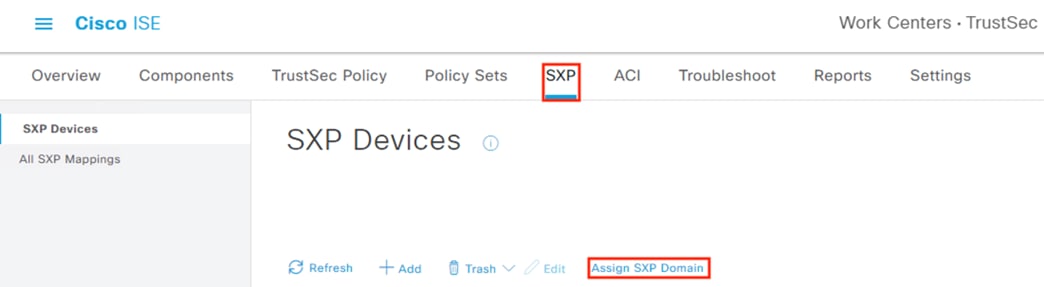
Step 2. Click on Create New SXP Domain.
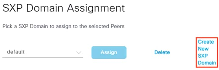
Step 3. Enter a name for the SXP domain, then click create. For this example, we’ll create an SXP domain for the application servers in the data center.
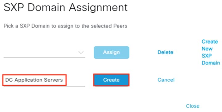
Step 4. Repeat the above steps to create SXP domains for different areas of the network. For this example, we’ll create a second SXP domain for the DC management network. This will cover Security Group assignments for all three devices in our workflow (endpoint, DNS server, application server), as the endpoint SGT is dynamically assigned. When finished, click Close.
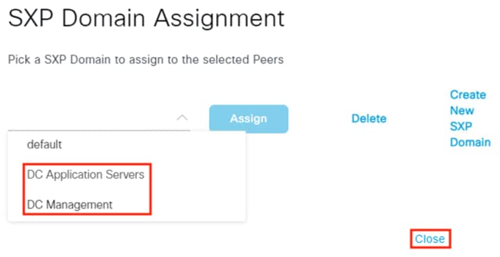
We’ll now add TrustSec switches as SXP devices and associate them with the applicable SXP domains. For this example, the datacenter access switch closest to the application servers will be associated with the DC Application Servers domain, and the datacenter access switch closest to the DNS server will be associated with the DC Management domain.
Step 1. From the SXP section of the TrustSec Work Center, click on Add.
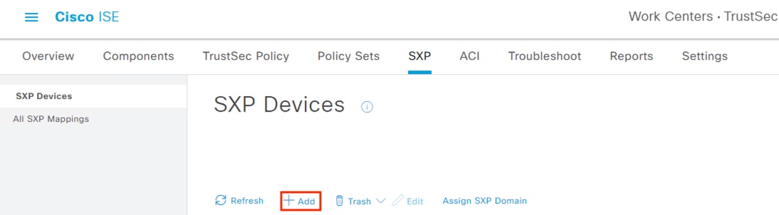
Step 2. Enter a name for the switch and set an IP address; set the Peer Role (here it is set as a Listener to ISE, but it can also be set to Both if the switch will perform a speaker function to other switches); specify one of the SXP domains configured in the prior section; leave the password type as default to use the password configured in the TrustSec SXP settings (note: you don’t enter a password on this screen when selecting default); click Save.
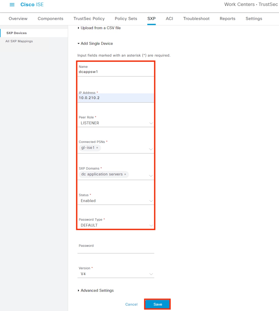
Step 3. Review the saved configuration and note that the status shows OFF.
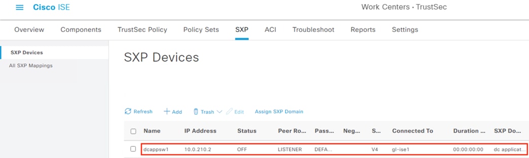
Step 4. The switch will reach an ON status after the configuration in the next section. Repeat the above steps to add additional switches and associate them to SXP domains. For this example, we’ll add a second switch associated with the DC Management domain.
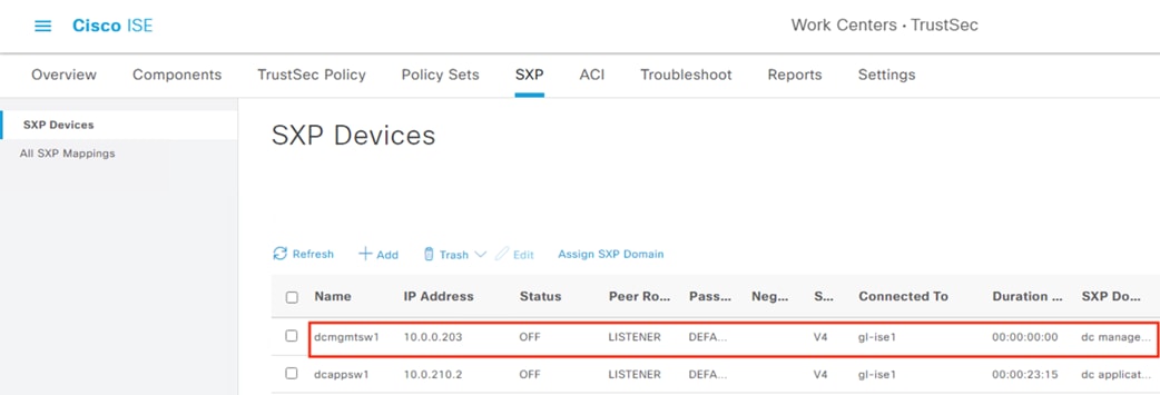
Step 1. Navigate to Configuration à Security à TrustSec.
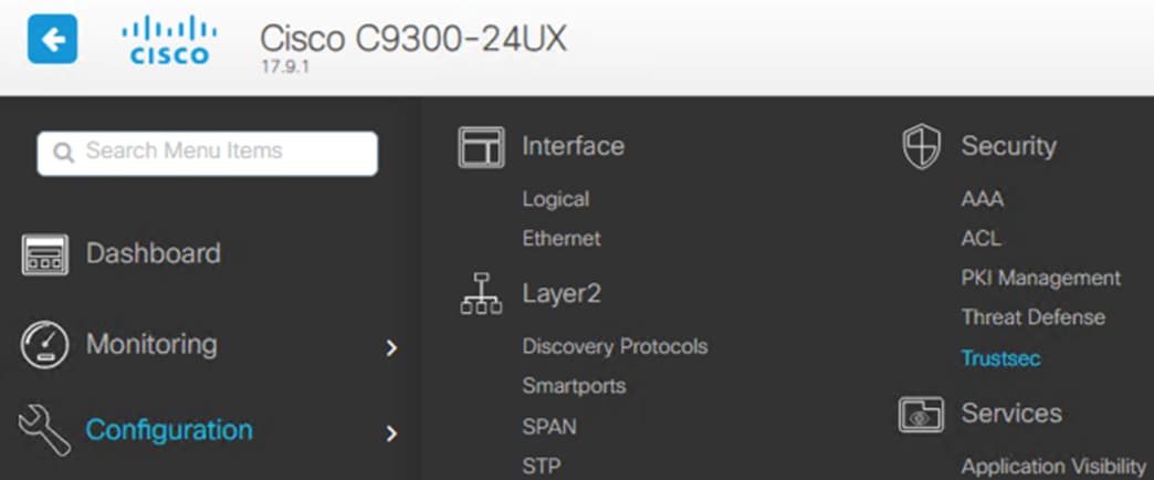
Step 2. Click on SXP.
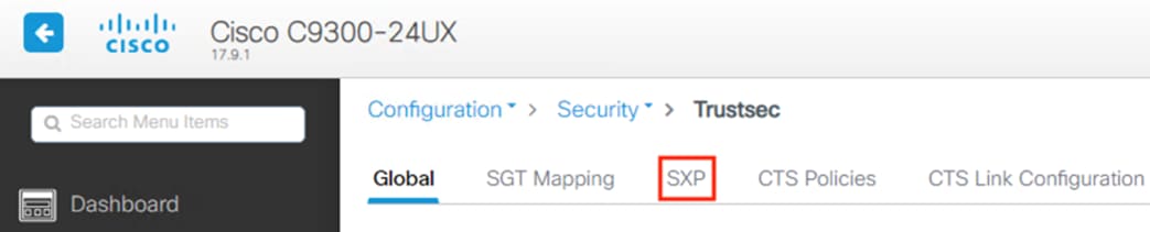
Step 3. Set SXP Status to Enabled, enter the IP of the switch interface or VLAN that will connect to ISE, and enter the password that was configured in the ISE SXP settings in the Configure SXP Settings section. Click Apply in the top right, then click the Add button beneath Peer Connections.
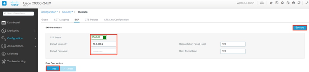
Step 4. Set the Mode to listener (or both, if this switch will also function as a speaker), set the Peer IP to the IP of the ISE node, set the Source IP that the switch will use to connect to ISE, and leave the password as default to use the password configured in the last screenshot. Set a VRF if applicable, then click Apply to Device.
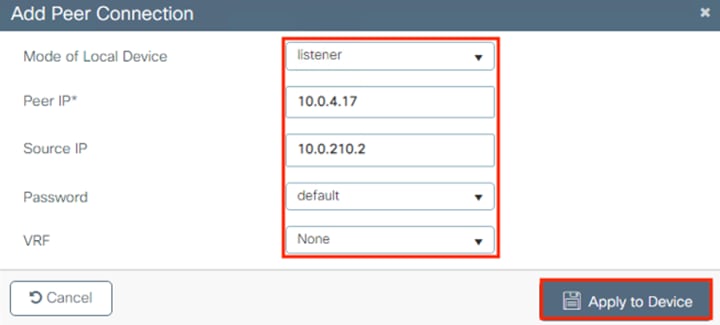
Step 5. To review or save the added running-config, click the Save Configuration icon.

Step 6. Click the Show Diff button to review configuration changes made since the last time running-config was copied to startup.
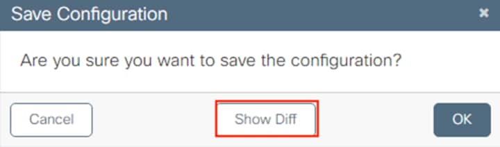
The above adds the following configuration to running-config.

Step 7. To save the running-config to startup-config, click Apply to Device.
Firewall: Confirm SXP Configuration
This step was already covered in the prior pxGrid configuration section.
Step 1. To verify the configuration, navigate to Integration à Other Integrations from the FMC.
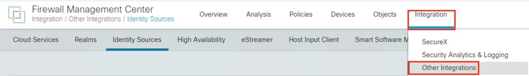
Step 2. Click on Identity Sources.
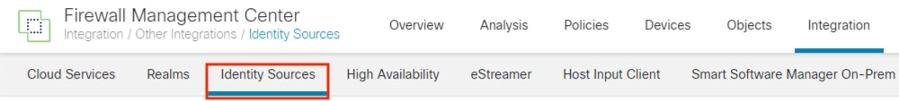
Step 3. Confirm that SXP topic is checked under the Identity Services Engine configuration.
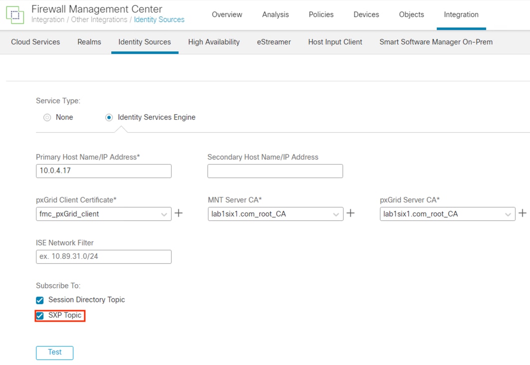
The Authentication and Authorization servers necessary for 802.1X were configured in the prior Configure AAA section.
Step 1. With the AAA configuration in place, navigate to Configuration à Interface à Ethernet to configure interfaces.
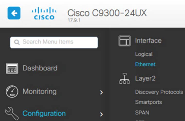
Step 2. Click a single interface or select multiple interfaces and click the Multi Port Configuration button (note: Multi Port Configuration will return the selected interfaces to a default configuration and is best used for initial setup). For this example, we will modify the Te1/0/1 interface.
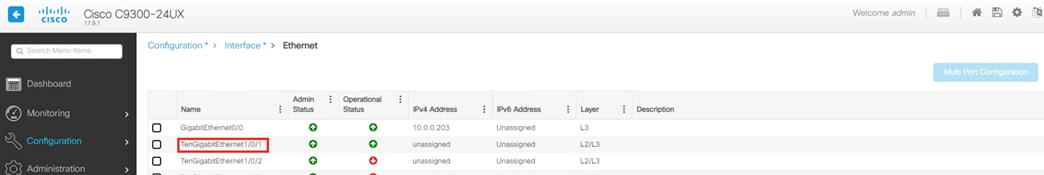
Step 3. Click Advanced.
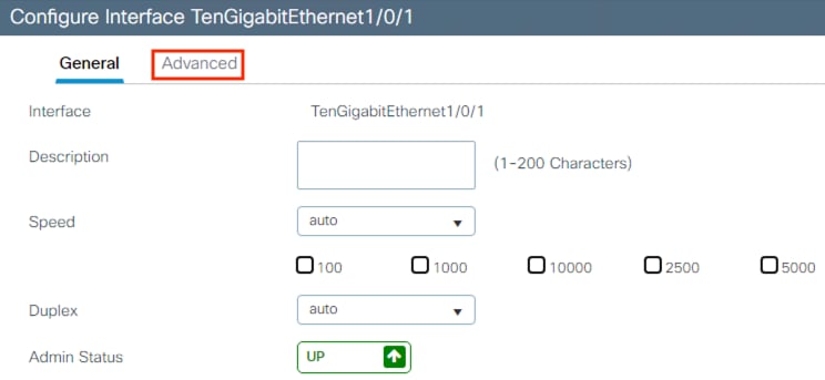
Step 4. Scroll down to the 802.1X Configuration section. In the below example, Authenticator Enabled configures the port for 802.1X and sets it to Access Port; Access-Session is set to closed for pre-authentication access; Authentication Order is set to use dot1x only, without MAB as a fallback option; Port Mode is set to Auto, which enables 802.1X authentication and sets the port to closed until an authentication is made; Host Mode is set to allow only a single host to access the port at any given time; finally, IP Device Tracking is set to enabled in order to maintain a table of IP and MAC addresses that access the port. After setting the config, click Update & Apply to Device.
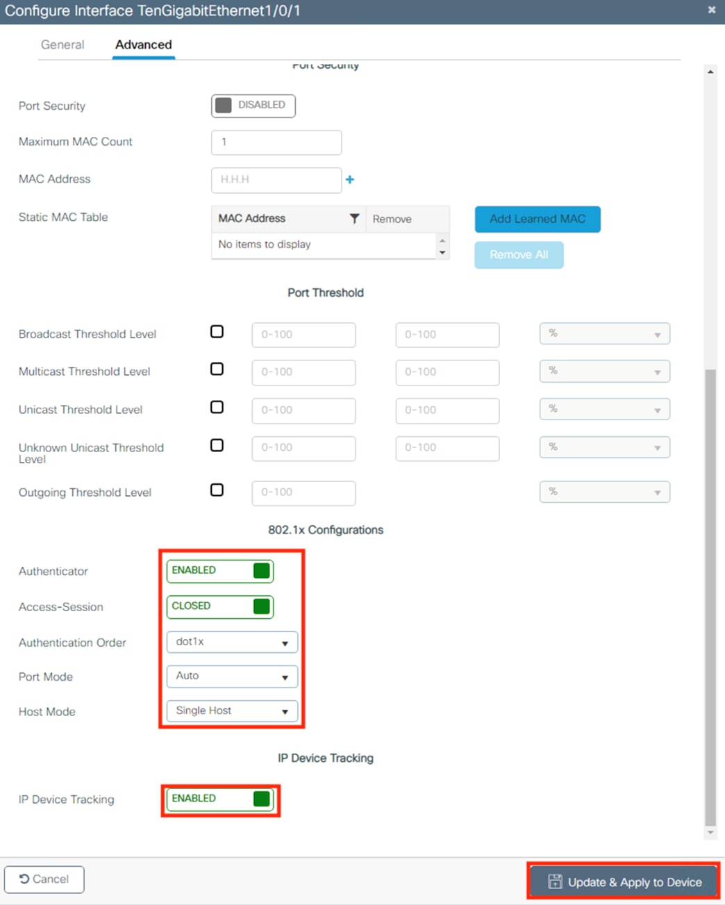
Step 5. We also need to enable 802.1X globally, which can only be done via command entry. To run the command from the GUI, navigate to Administration à Command Line Interface.
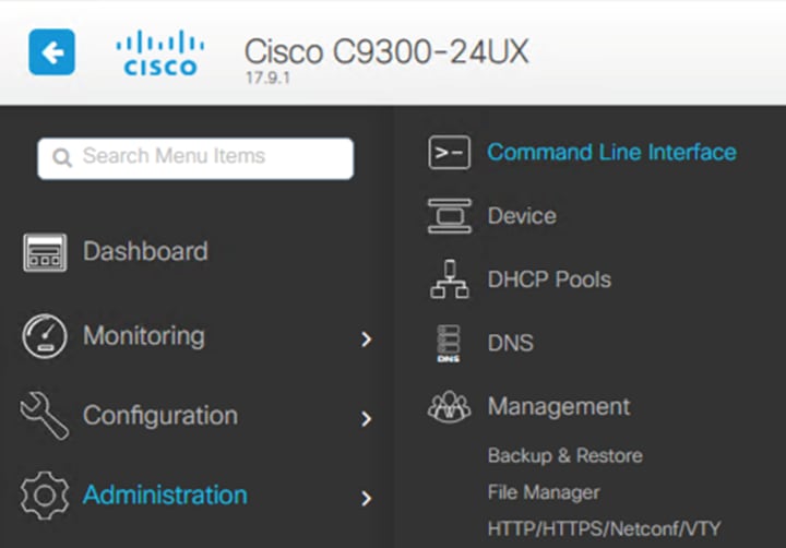
Step 6. Select the Configure radio button and enter the following configuration to globally enable Dot1x: dot1x system-auth-control
Step 7. Click the Run Command button.
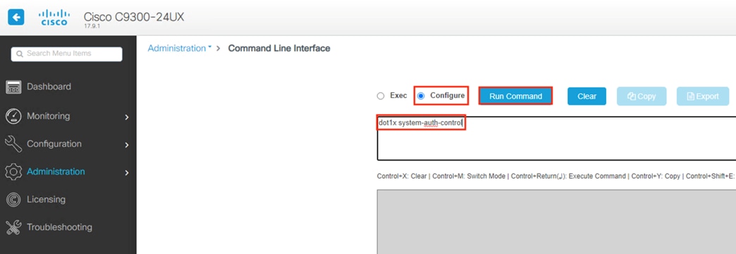
The above configuration adds the following lines in green to running-config.
![]()

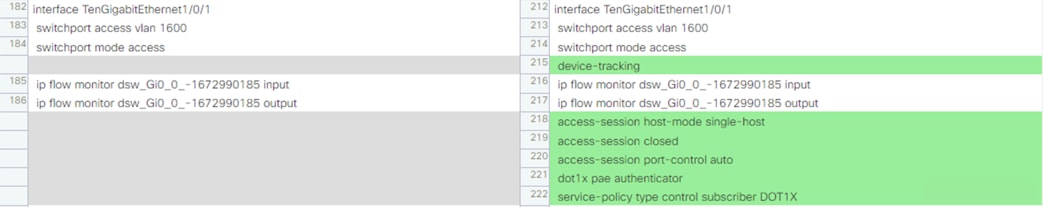
Configure ISE Security Groups and Static Mapping
We’ll now configure the ISE Security Groups (SGs) that will be used for the TrustSec Matrix, 802.1X, ISE AA policies, and Secure Firewall source and destination SGTs. These groups will form the backbone of the RBAC configuration in the remainder of the guide.
ISE: Configure Security Groups
Step 1. From the Cisco ISE GUI, click the Menu and choose Work Centers à TrustSec à Components.
![]()
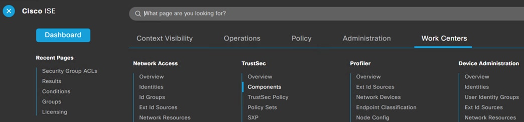
The Components page should open with the Security Groups tab selected.
Note: ISE has default groups for Contractors, Employees, and Guests.
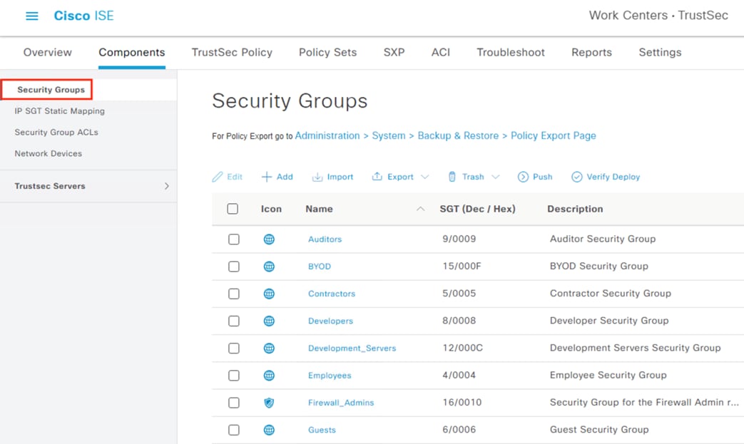
To give more granular control of user access and improve device validation, we’ll create Trusted and Untrusted groups for employees and contractors. We’ll also create a Machine Security Group that allows restricted access for devices that pass machine authentication but have not yet passed user authentication, and a Guest_Registration Security Group to cover the initial guest to ISE connection that occurs during guest registration, but before the Guest SGT is assigned. We’ll also create static destination SGs for ISE, DNS servers, and application servers.
Step 2. Click the Add button.
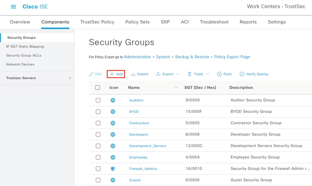
Step 3. Name the group Employee_Trusted_Device, select an Icon, and enter a Description if desired. Click Submit at the bottom of the page.
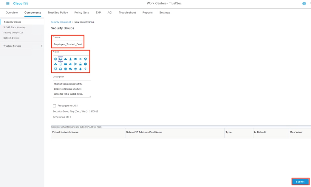
Step 4. Repeat the steps to create trusted and untrusted groups for employees and contractors.
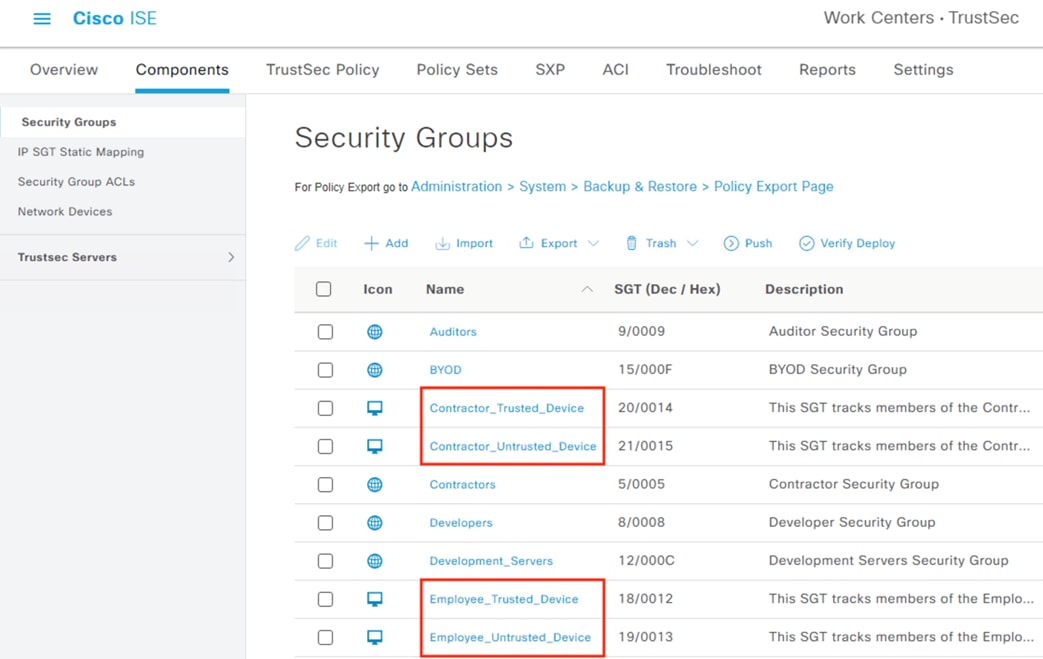
Step 5. Create an additional SGT for machine authentication.
Note: The NAM endpoint deployment will attempt an initial machine authentication, at which point we can assign an SGT. If a user then attempts a user login using the same endpoint, they will be assigned one of the Contractor or Employee SGTs based on the results of their combined machine and user auth.
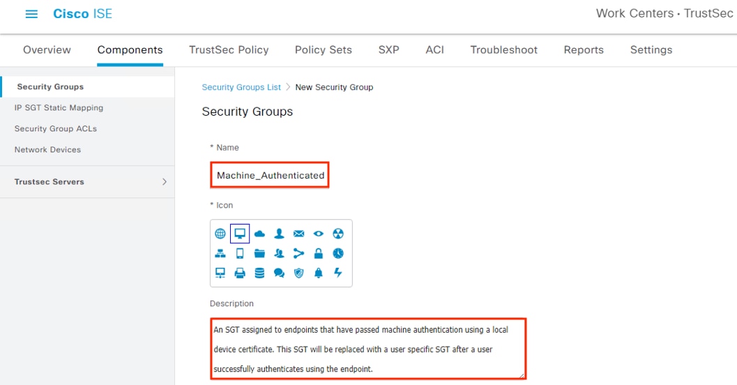
Step 6. Create SGTs for Guest_Registration and ISE, which will give us a cleaner firewall rule for the initial guest redirect to ISE during guest registration. SGs for Guest_Registration, the default Guests SG, ISE, and Machine_Authenticated are shown below.
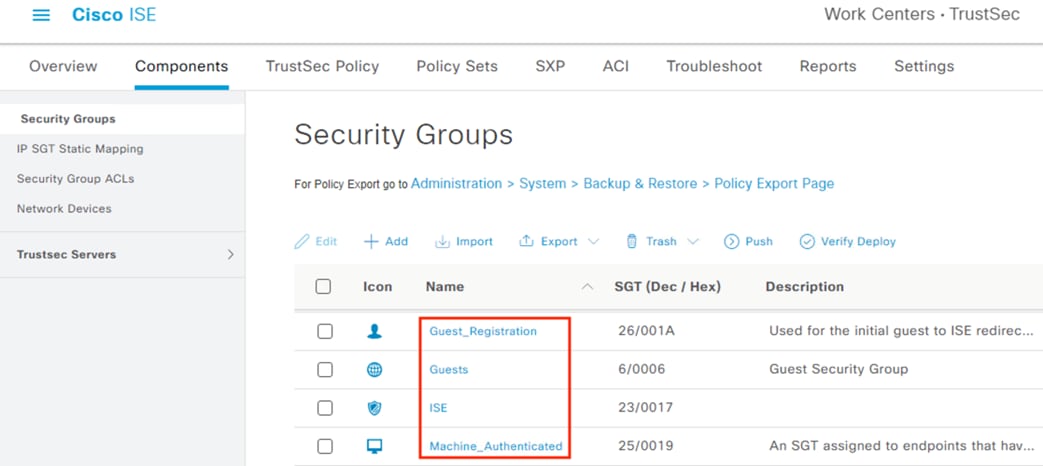
Step 7. Create an SGT to statically assign to our application servers, which will be the destination used in Dynamic SGT connection testing, and to our DNS servers, which will be needed to resolve the URLs associated with the application servers.
Repeat the Add steps to create a DC_Application_Servers group and a DC_DNS_Servers group (the DC naming convention reflects that both resources are in the datacenter for this example).
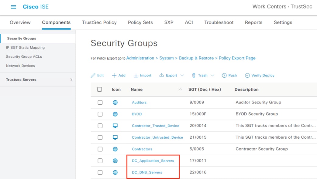
Step 8. Push the updated groups to connected devices.
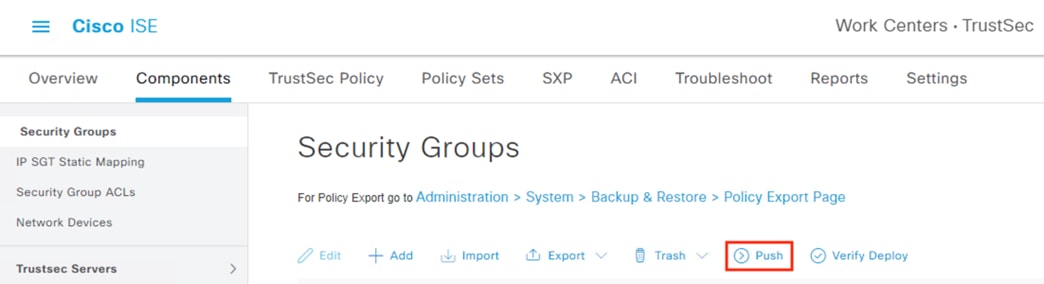
Step 1. To confirm the security groups are populated to the switches, run the cts show environment data command.
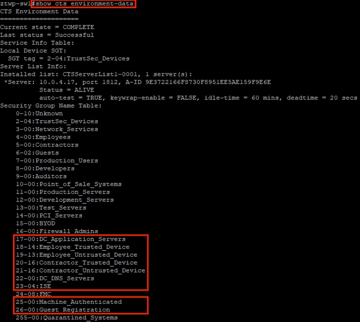
Step 2. If the expected security groups have not synced yet, run the following command to prompt the switch to retrieve the security groups from ISE:
# cts refresh environment-data
ISE: Configure Security Group Static Mapping
The application servers configured in the last section have a reserved pool of IP addresses, which we can statically map now. In addition, the ISE servers needed for Guest registration and the DNS servers needed to resolve the hostnames of the applications have static IP assignments.
Step 1. Click the IP SGT Static Mapping tab, then click Add.
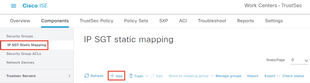
Step 2. Specify the IP address(es), leave the radio selection on Map to SGT Individually, select the DC_Application_Servers SGT, send the mapping to the DC Application Servers SXP domain, and select TrustSec devices to deploy the mapping to. Click Save.
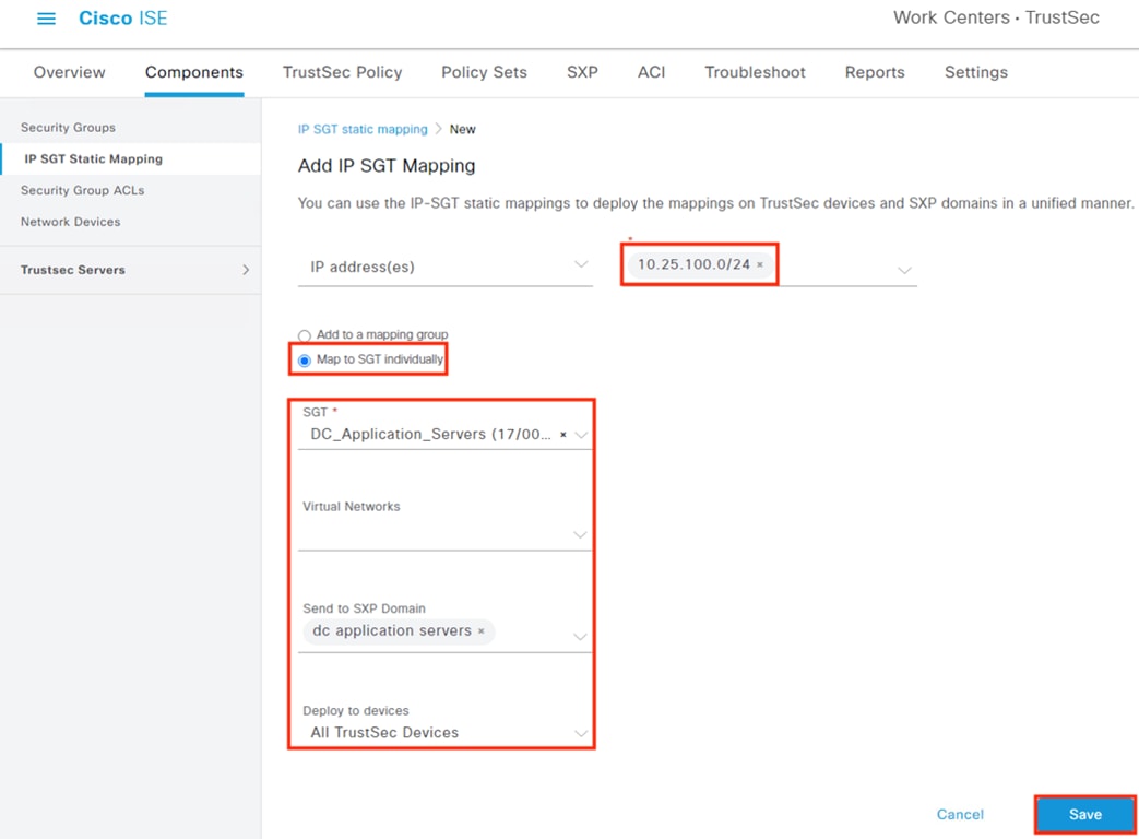
Step 3. Repeat the steps to add the DNS servers.
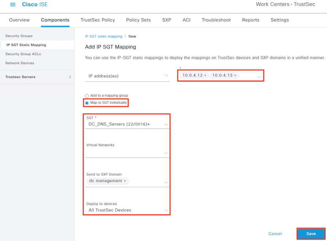
Step 4. Repeat the steps to add static mappings for ISE. Review the mapping details, then click Deploy.
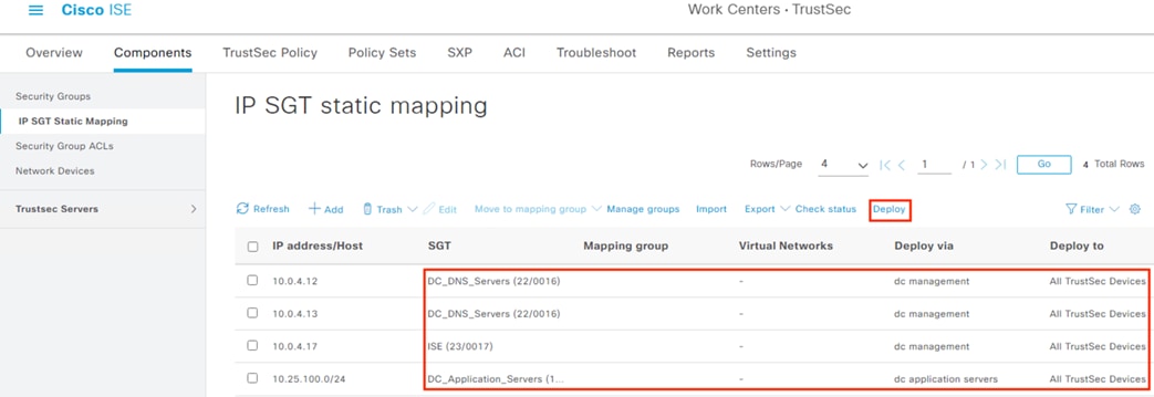
Step 5. Confirm the applicable switches are checked, then click Apply.
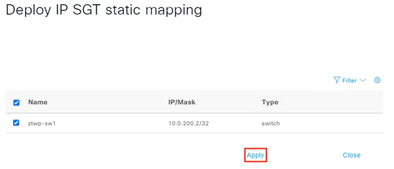
Step 6. Click OK at the warning.

Step 7. Confirm successful mappings, then click Close.
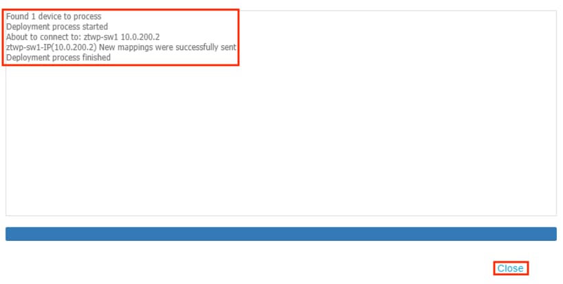
The example flows we covered at the start of this document include employees and contractors accessing private applications, and guest users accessing the internet. The employee and contractor connections will both be made over HTTPS and require an internal DNS resolution. Prospective guest users will also need to make an initial connection to the ISE Guest Registration portal to complete registration before accessing the internet. In this section we’ll add basic rules to allow the necessary HTTPS, DNS, guest portal, and internet connectivity, and set an implicit deny for all other connections.
Switch: Configure CTS Role-Based Enforcement
In addition to the prior TrustSec configuration, there is an additional configuration necessary for the switch to receive and enforce SGACLs.
Step 1. From the GUI, navigate to Configuration à TrustSec.
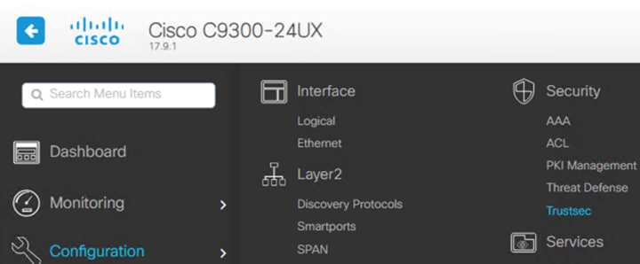
Step 2. Click on CTS Policies.
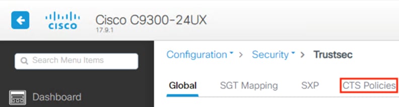
Step 3. Enter the VLAN associated with the SGACL (note: this can be set to include all VLANs on the CLI, if needed) and toggle the Global setting to Enabled. Click Apply.
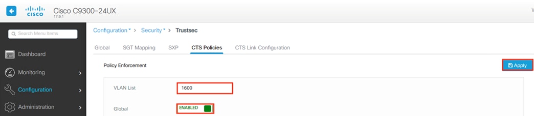
Step 4. Click the save icon to review the configuration change details.

Step 5. Click Show Diff.
The above config applies the following change to the backend.
![]()
Step 6. Click Apply to Device to copy the running-config to startup-config.
![]()
Note: it’s also possible to configure TrustSec switches in a monitor only mode to verify connections are permitted and denied as expected. For configuration steps, please see the Cisco TrustSec Configuration Guide.
ISE: Configure Security Group ACLs
Step 1. Navigate to Work Centers à TrustSec à Components.
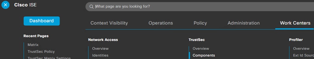
Step 2. On the left side, click on Security Group ACLs.
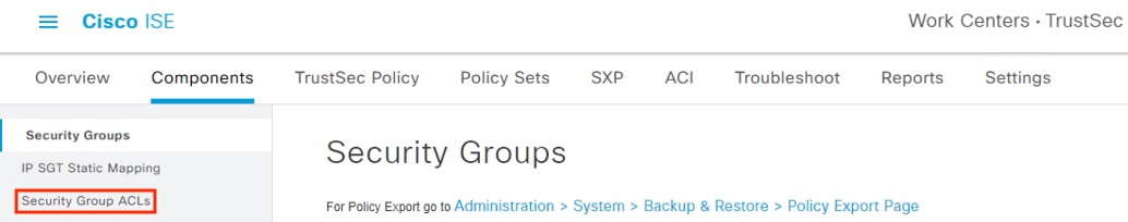
Step 3. Click the Add button.
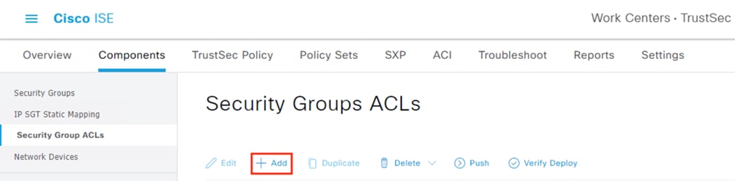
Step 4. Create a basic rule to allow an outbound HTTPS connection. Name the rule Permit_HTTPS_Request and enter ‘permit tcp dst eq 443’ for the rule content. Click Submit.
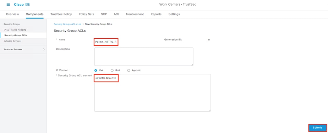
Note: SGACLs are not stateful, so we’ll also need a rule to allow the return traffic.
Step 5. Click Add again to create an ACL for the return traffic.
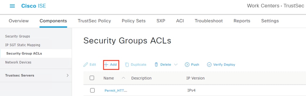
Step 6. Name this rule Permit_HTTPS_Response and give it criteria ‘permit tcp src eq 443’. Click Submit.
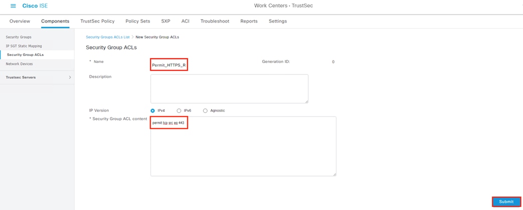
Step 7. Click Add again.
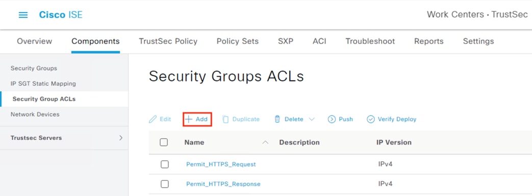
Step 8. Name the rule Permit_DNS_Request and add ‘permit udp dst 53’ in the content area. Click Submit.
Note: DNS can also use TCP for requests or responses that exceed UDP byte limits; while this isn’t common, DNS over TCP can also be allowed here if desired.
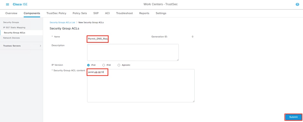
Step 9. Click Add again and create a rule titled Permit_DNS_Response with content ‘permit udp src 53’. Click Submit.
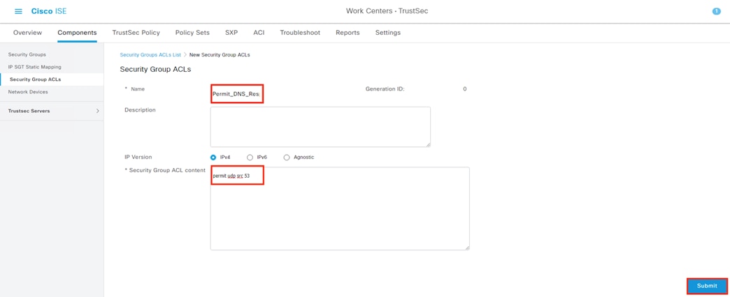
Step 10. Confirm the created rules appear, then click on TrustSec Policy.
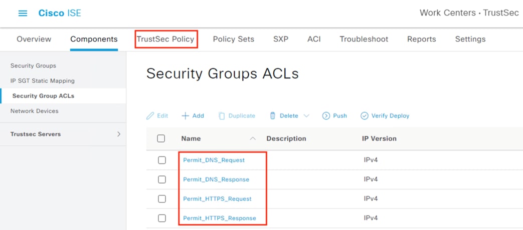
ISE: Configure TrustSec Matrix
Step 1. From the TrustSec Policy page, click Matrix.
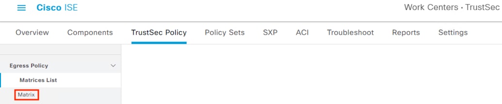
Step 2. It can save time to create a custom view with only groups we will be modifying. Click the dropdown on the right side and select ‘Create custom view’.

Step 3. Give the view a name and add the Security Groups created previously to both Source and Destination. Choose Name in the Sort Matrix By dropdown. Click Save.
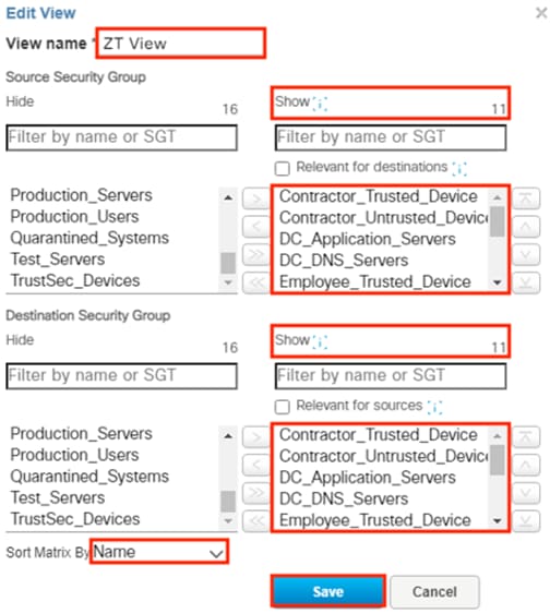
Step 4. The custom view will load automatically and can be selected from the right dropdown. Click the box for source Contractor_Trusted_Device and destination DC_Application_Servers, then click the pencil icon to edit.
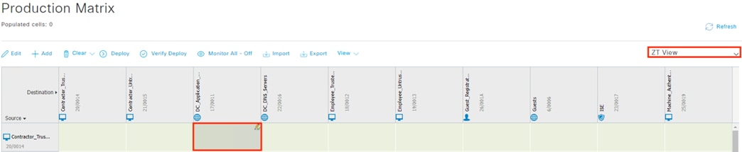
Step 5. Set the ACL to Permit_HTTPS_Request, then click Save.
Note: In this example we leave the Catch All rule set to None for the rules and rely on a Default Deny for the policy, but the Catch All rule can be configured by rule if preferred.
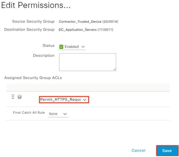
The matrix updates the cell with a blue color and the text of the applied ACL.
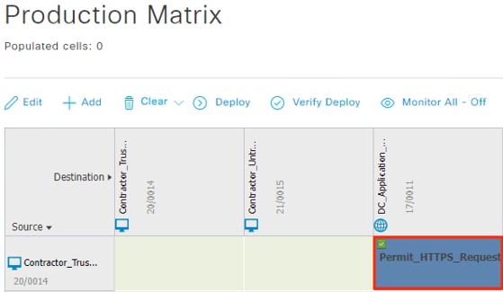
Step 6. Repeat the steps to allow HTTPS requests for all four contractor and employee Security Groups.
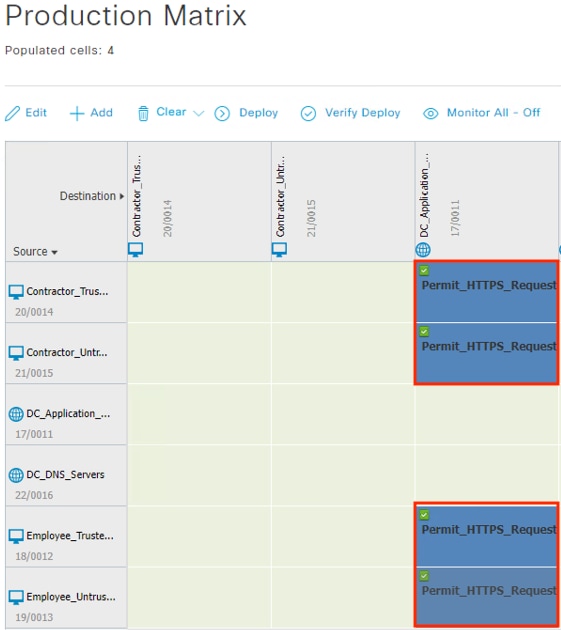
Step 7. Permit DNS requests from the four employee and contractor Security Groups to the DC_DNS_Servers Security Group.
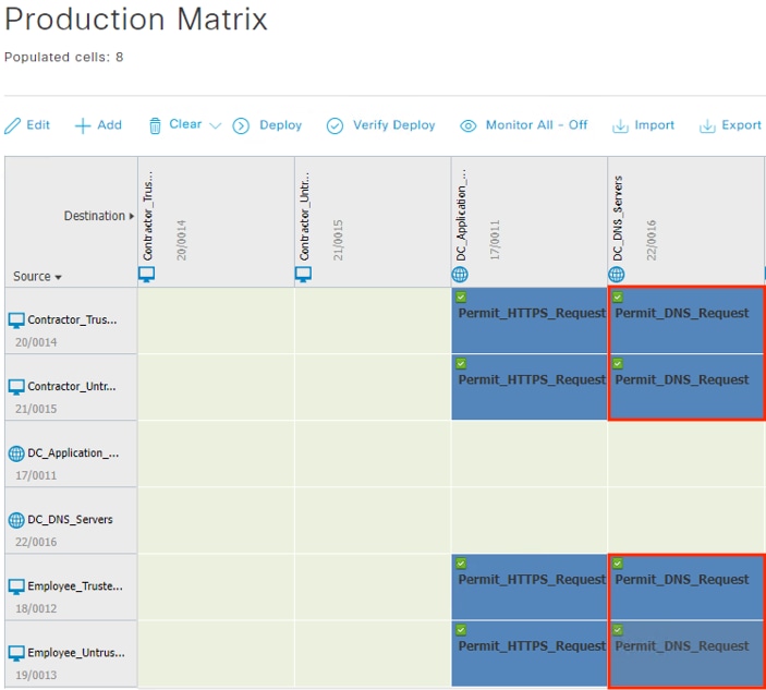
Step 8. Allow the return traffic for the HTTPS and DNS requests. These connections will have the DNS and Application servers as the source, the employee and contractor groups as the destination, and use the DNS_Response and HTTPS_Response ACLs.
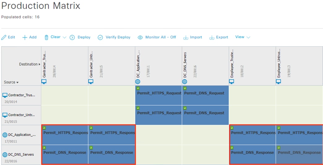
Step 9. Permit the Guest_Registration Security Group to connect to the ISE Security Group over HTTPS and permit the HTTPS Response from ISE to Guest_Registration.
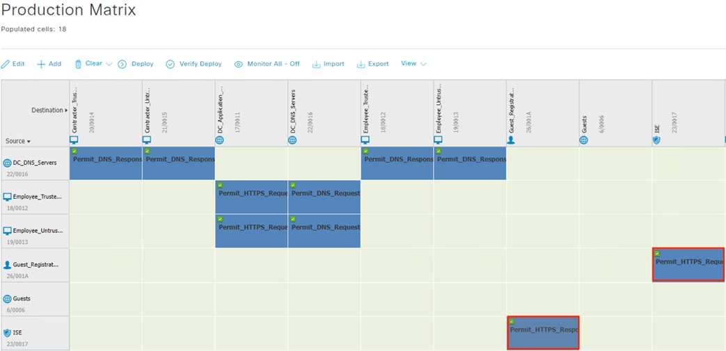
Allow the Guests and Machine_Authenticated Security Groups to access the Unknown Security Group. Rather than map all public IP spaces to an Internet Security Group, common practice is to map all internal IP space to Security Groups and then use the Unknown Security Group to represent ‘not internal’.
Step 10. Click the cell for Guests to Unknown, then click the pencil to edit.
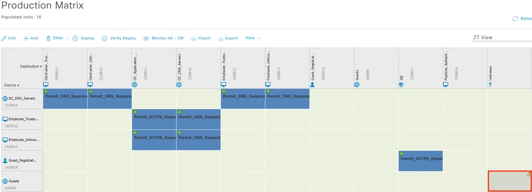
Step 11. Set the Final Catch All Rule to Permit IP, then click Save.
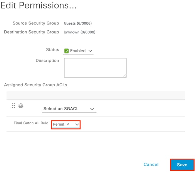
Step 12. Repeat the process to permit traffic from the Machine_Authenticated Security Group to the Unknown Security Group and permit the return traffic from Unknown to Guests and Machine_Authenticated.
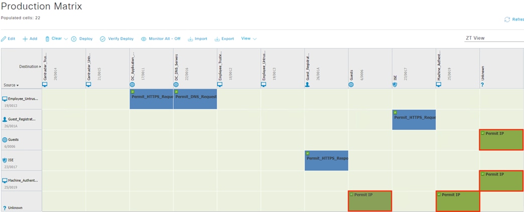
Note: Although the Matrix allows all traffic from Unknown IPs to Guest and Machine_Authenticated SGTs, stateful firewalls will deny any inbound connections to the Guest and Machine_Authenticated Security Groups. Only return traffic to outbound connections will be permitted by the firewall.
Step 13. Click on the Default link and set the default SGACL to Deny_IP_Log. Click Deploy.
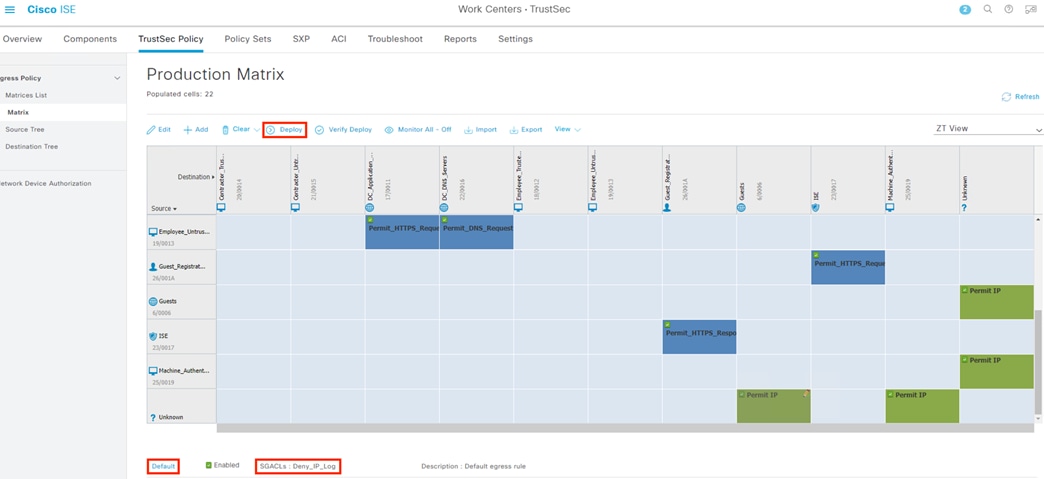
ISE Authentication and Authorization Policy Preparation
In addition to the ISE Profile checks, we will also perform both user and machine authentication for each 802.1X connection. Combining user and machine authentication requires EAP Chaining, which we’ll accomplish using the AnyConnect NAM and EAP-FAST.
Our AA configuration will leverage several certificates and endpoint configurations, specifically:
● A CA signed ISE certificate used for EAP connections. This will serve the function of server validation for the endpoint. Configuration is given in this section.
o The EAP certificate must be trusted by the endpoint. Steps to upload the certificate to the NAM profile configuration and distribute via Meraki MDM are provided in the Zero Trust User and Device guide.
● Trusted devices have a CA signed client authentication certificate installed.
o Steps to distribute machine certificates via GPO from an Active Directory CA are provided in the companion Certificate Guide under the section Active Directory: Distribute Machine Certificates via Group Policy Object.
● ISE must trust the root and any intermediary certificates in the client auth certificate chain on the endpoint. These will be used to validate the client certificate during EAP-FAST negotiation. Configuration is given in this section.
● Trusted devices have the NAM AnyConnect module installed with a profile that specifies server and client certificate validation. The NAM and profile settings are provisioned via Meraki MDM as covered in the Zero Trust: User and Device Security Design Guide.
o The NAM configuration will supersede any existing 802.1X configuration on the endpoint. NAM will initiate 802.1X connections using EAP-FAST.
ISE: Configure EAP Certificate
Step 1. Navigate to Administration à System à Certificates.
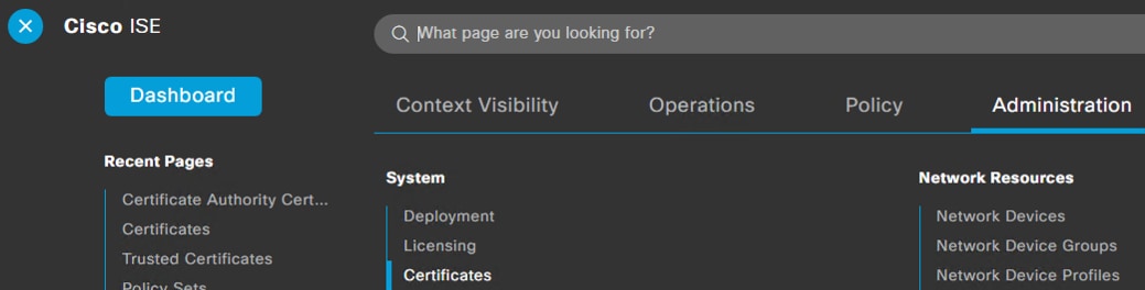
Step 2. Click on Certificate Signing Requests.
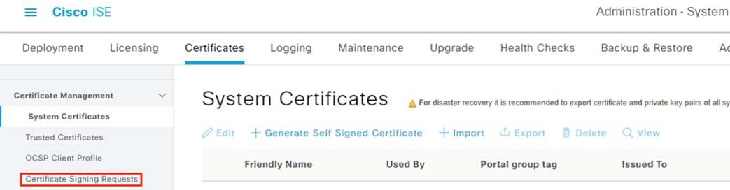
Step 3. Click on the Generate Certificate Signing Requests button.
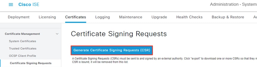
Step 4. Set the Usage to EAP Authentication and select the node(s) to generate the CSR for. Set Subject, SAN, and Key settings. Click the Generate button.
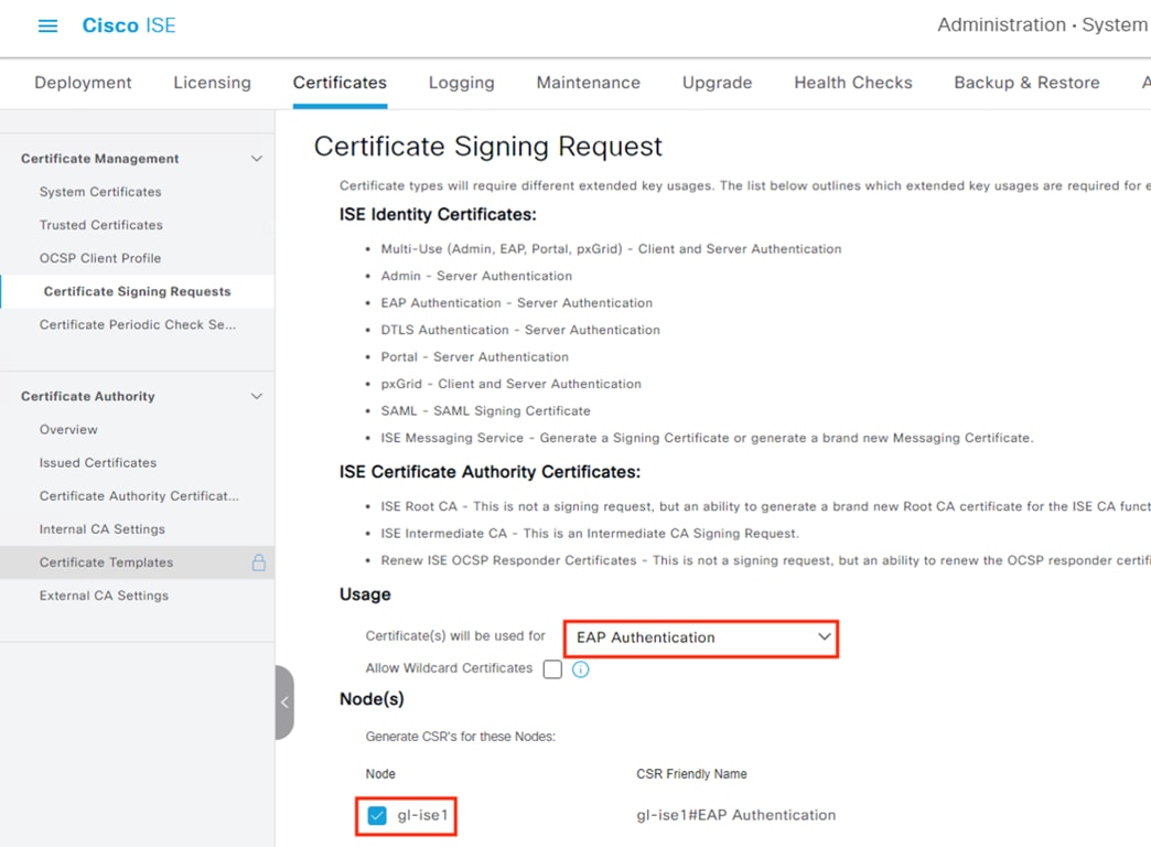
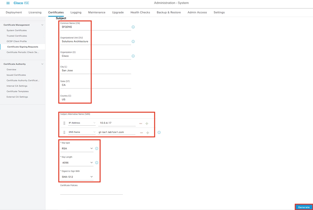
Step 5. Click the Export button and save the CSR.
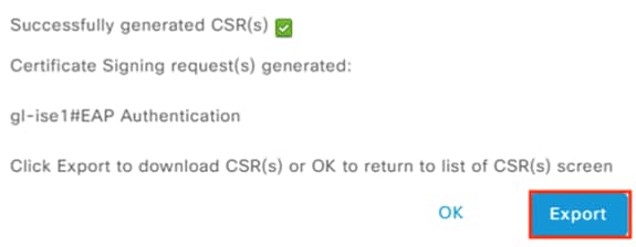
Step 6. Use a CA server to generate a Base 64 encoded certificate in a format that will be accepted by ISE, such as .cer. For a Windows CA, the Web Server template is adequate. For full certificate generation procedures using a Windows CA, please refer to the Create Certificates from CSRs using an AD Certificate Authority section in the Appendix.
Step 7. Return to the Certificate Signing Requests page in ISE. Check the box next to the CSR request, then click Bind Certificate.
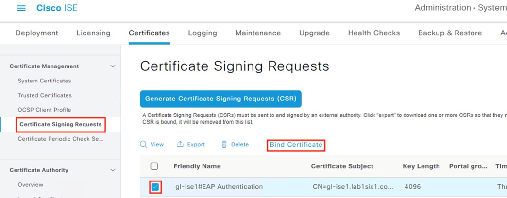
Step 8. Upload the certificate file retrieved from Active Directory, set a Friendly Name, confirm the EAP Authentication box is checked, then click Submit.
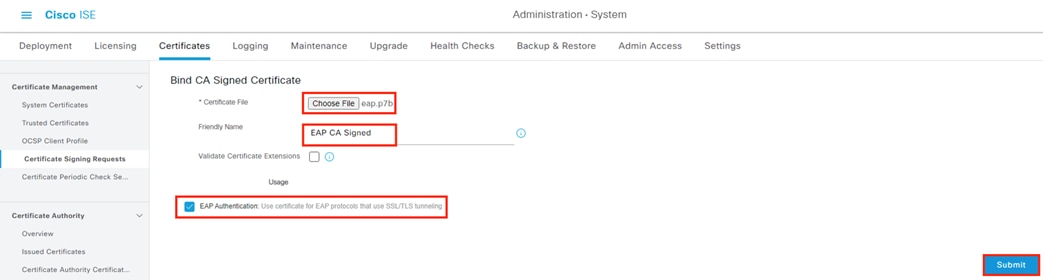
Step 9. A prompt will appear if there is a prior EAP certificate (ISE generates a default self-signed certificate, which this certificate will replace for EAP connections). Click Yes to replace the prior certificate.
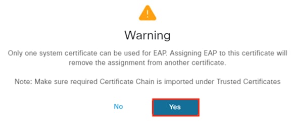
Step 10. To verify certificate install, click on the System Certificates link.
Step 11. Confirm the uploaded certificate is associated with EAP Authentication.
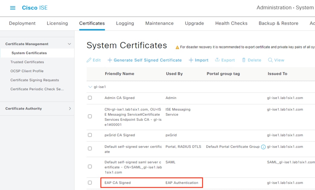
ISE: Configure EAP Chaining Settings
Step 1. Click the Menu icon (![]() ) and navigate to Policy à Policy Elements à Results.
) and navigate to Policy à Policy Elements à Results.
Step 2. From Authentication à Allowed Protocols, click on Default Network Access.
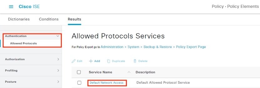
Scroll down to the EAP-FAST section and verify the following settings are enabled.
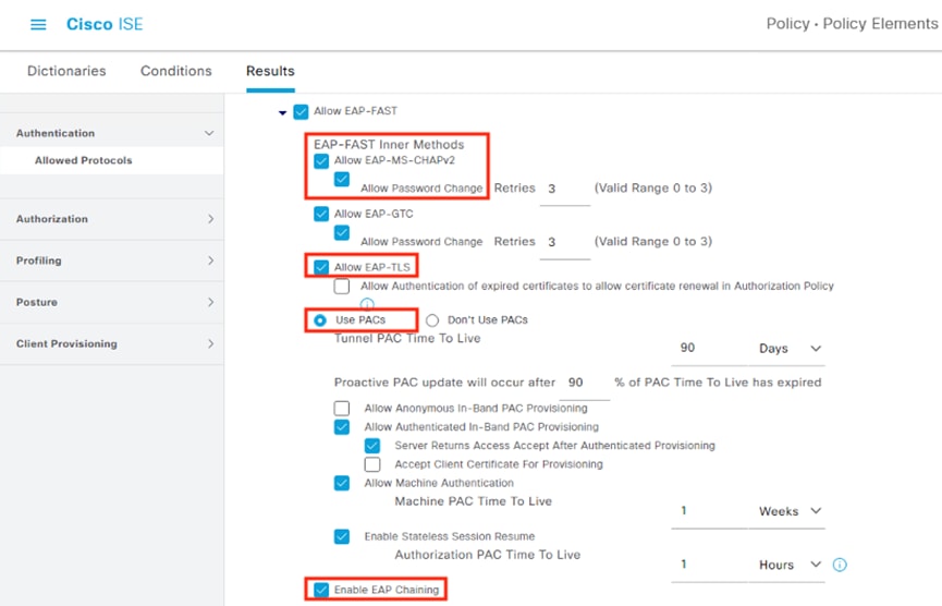
Step 3. Scroll down and click Save when finished.
ISE: Verify Certificate Authentication Profile Settings
Step 1. Click the Menu icon (![]() ) and navigate to Work Centers à Network Access à Ext Identity Sources.
) and navigate to Work Centers à Network Access à Ext Identity Sources.
Step 2. Click on Preloaded_Certificate_Profile.
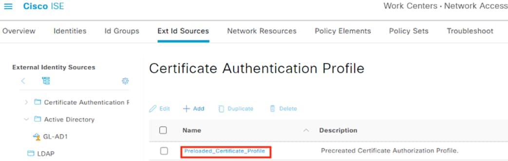
Step 3. Verify that the Certificate Attribute is set to the Subject Common Name. Click Save when finished.
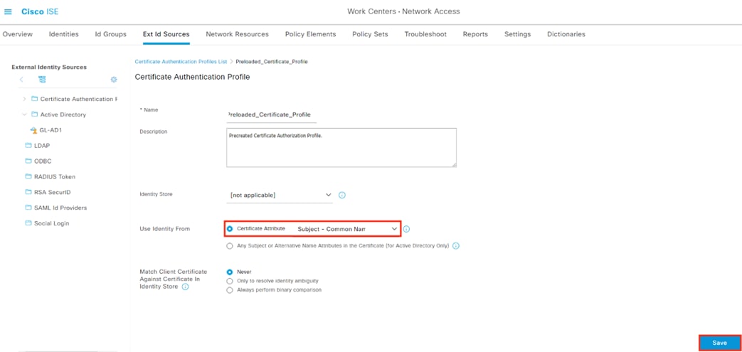
Step 4. Click the Identities tab, then click Identity Source Sequences. Edit All_User_ID_Stores.
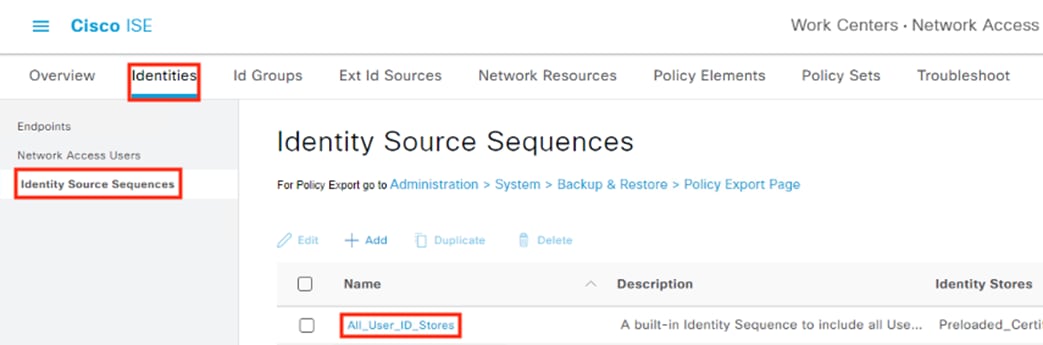
Step 5. Confirm that the Preloaded_Certificate_Profile configured in the prior step is selected for Certificate Based Authentication. Click Save.
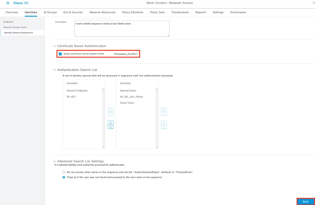
Windows: Confirm Machine Auth Certificate Details
Instructions for deploying certificates for machine authentication via Group Policy Object (GPO) are given in the companion Certifcate Guide under the Acitve Directory: Distribute Machine Certificates via Group Policy Object section. Steps to verify the location and details of a machine certificate are given below.
Step 1. From a Windows workstation, search for the term ‘cert’ and select the ‘Manage computer certificates’ entry to review local certificates that apply to all users on the endpoint.
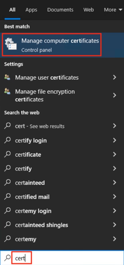
Step 2. Click the dropdown arrow next to Personal, then click the Certificates subfolder. Any certificates in the folder appear in the right window pane. Note that the certificate is personalized for the specific endpoint it is installed on (in this example, computer name J0PDU4H). Double click the certificate to open it.
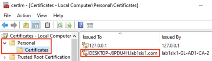
Step 3. Click the Details tab and then scroll down and click on Enhanced Key Usage. Verify there is an entry for Client Authentication.
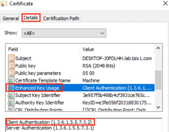
Step 4. Click on the Certification Path tab and review the certificate chain details. Click OK when finished.
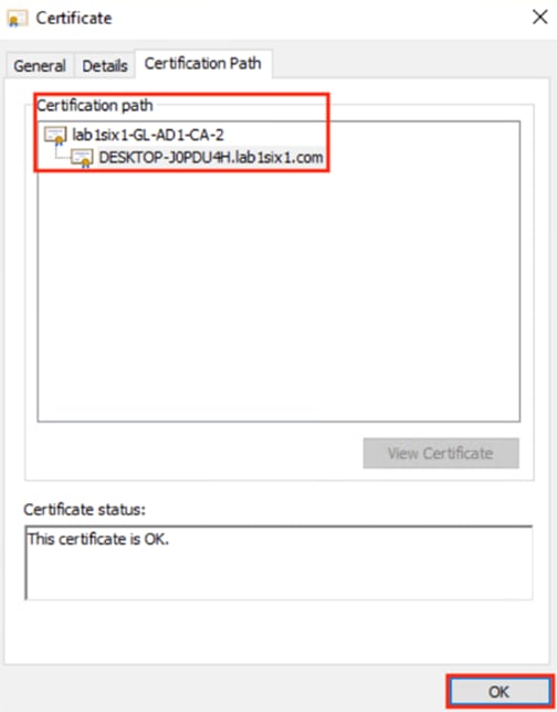
In this case our certificate is signed by only a root CA, which was already added to the ISE Trusted Certificates store in a prior section. For steps to export an AD root certificate (or intermediary certificate) and add it to the ISE Trusted Certificates store, see the Export a Root Certificate section in the companion Certificate Guide.
Step 5. Continue to the next section for steps to verify the certificates in the ISE Trusted Certificates store and configure them for client authentication.
ISE: Configure Trusted Certificates for Client Authentication
With the NAM profile configuration set in the Zero Trust User and Device guide, each endpoint will present a client certificate during 802.1X machine authentication. For ISE to accept the client certificate presented by an endpoint, the root and any intermediate certificates in the client certificate chain must be set to trust for client authentication within ISE.
Step 1. Click the Menu icon (![]() ) and navigate to Administration à System à Certificates.
) and navigate to Administration à System à Certificates.
Step 2. Click on Trusted Certificates.
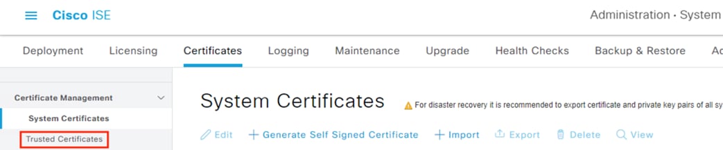
Step 3. Select the root certificate that signed the client certificate used by the endpoint then click Edit.
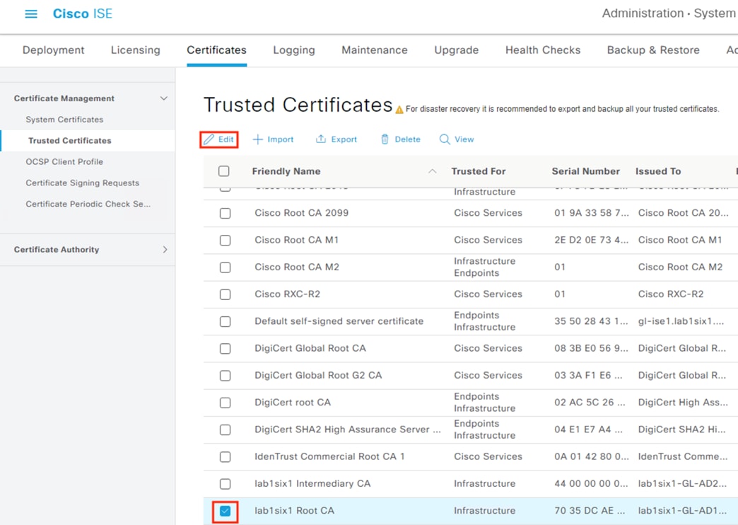
Step 4. Check the box for ‘Trust for client authentication and Syslog’, then click Save.
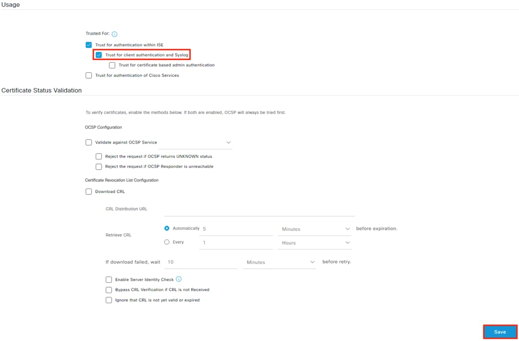
Step 5. Repeat the process above for any intermediate CAs in the client certificate chain.
ISE: Confirm Machine Authentication is Enabled
Machine Authentication must be enabled for ISE to validate the endpoint based on the client certificate.
Step 1. Click the Menu icon (![]() ) and navigate to Work Centers à Network Access à Ext Id Sources.
) and navigate to Work Centers à Network Access à Ext Id Sources.
Step 2. Select an Active Directory instance.
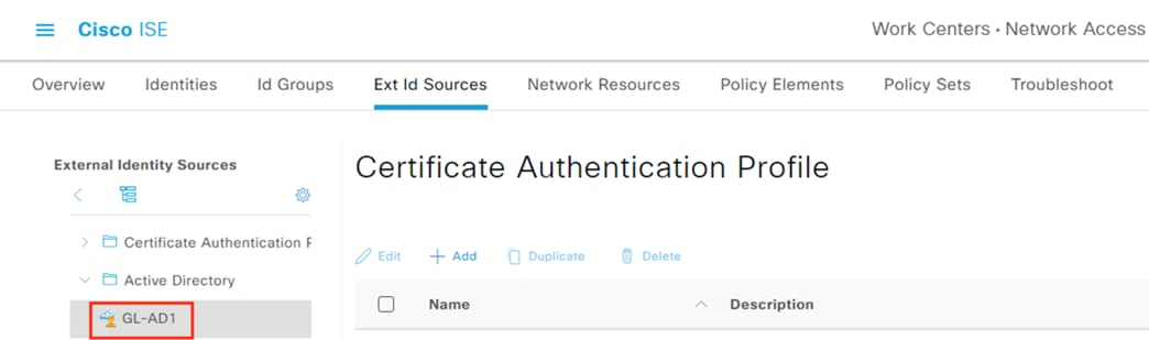
Step 3. Click Advanced Settings.
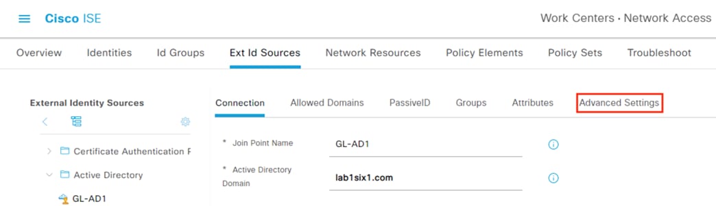
Step 4. Confirm that Enable Machine Authentication is checked.
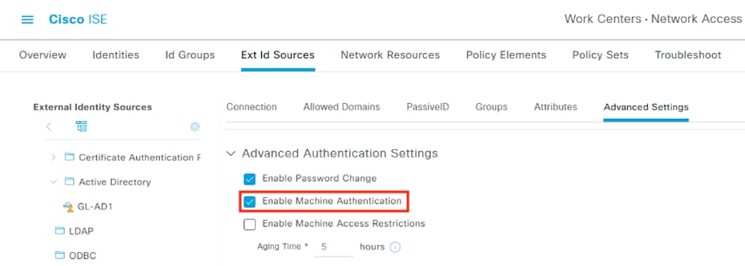
Note: Machine Access Restrictions (MAR) is not needed for this configuration because EAP-FAST can perform the client authentication and machine authentication together; this allows us to reliably authorize the user, even if there is not a machine authentication cached via MAR within the Aging Time window.
Configure the Authentication and Authorization rules that will be used to provide AA for 802.1X connections (configured in the next section), and assign dynamic SGTs to permitted 802.1X connections for enforcement via Secure Firewall and SGACLs.
Step 1. Click the Menu icon (![]() ) and navigate to Policy à Policy Sets.
) and navigate to Policy à Policy Sets.
Step 2. Edit an existing policy or click the + icon to create a new one.
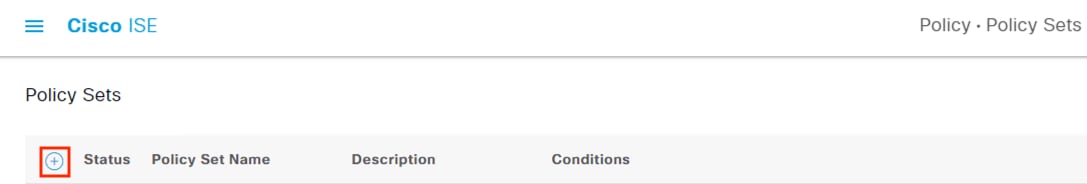
Step 3. Name the policy and set the Allowed Protocols to Default Network Access, then click the + icon.
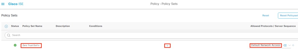
Step 4. Drag the Wired_802.1X library condition to the NEW | AND | OR box.
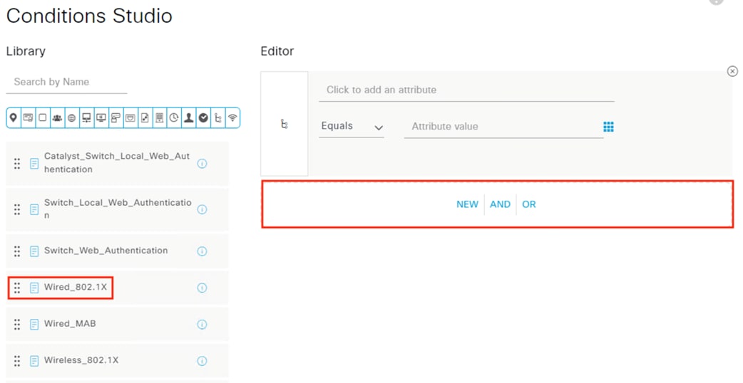
Step 5. Drag the Wireless_802.1X library condition to the NEW | AND | OR box.
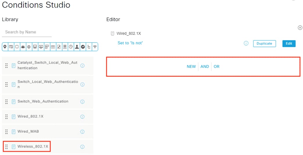
Step 6. Set the condition to OR. If desired, mouse over the Wired_802.1X and Wireless_802.1X and click edit to change the premade conditions to their expanded format.
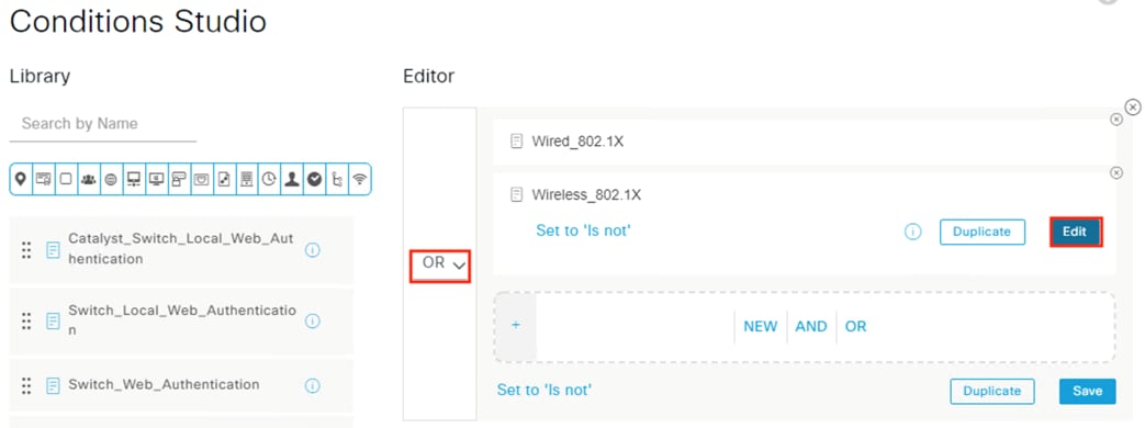
The expanded conditions are shown below for reference (the behavior will be the same regardless of whether they are expanded). Click Use at the bottom of the page.
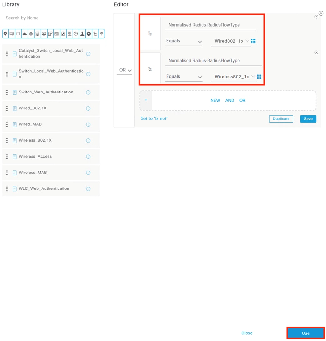
Step 7. Click Save.
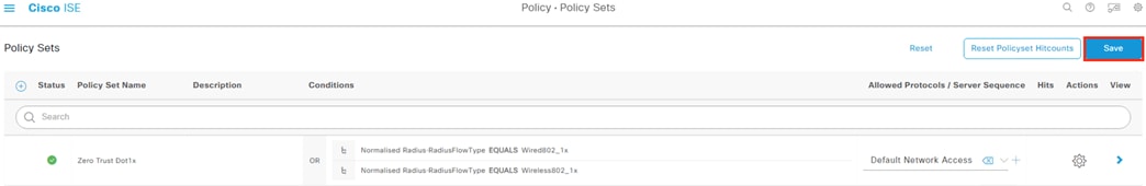
Step 8. Click on the > icon for the new policy.

ISE: Create Authentication Policy Rules
Step 1. Expand the Authentication Policy, then click the + icon.
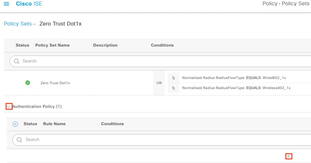
Step 2. Name the rule and set the Use column to All_User_ID_Stores (other options can be selected with more narrow criteria, if desired). Click the + icon to set conditions.
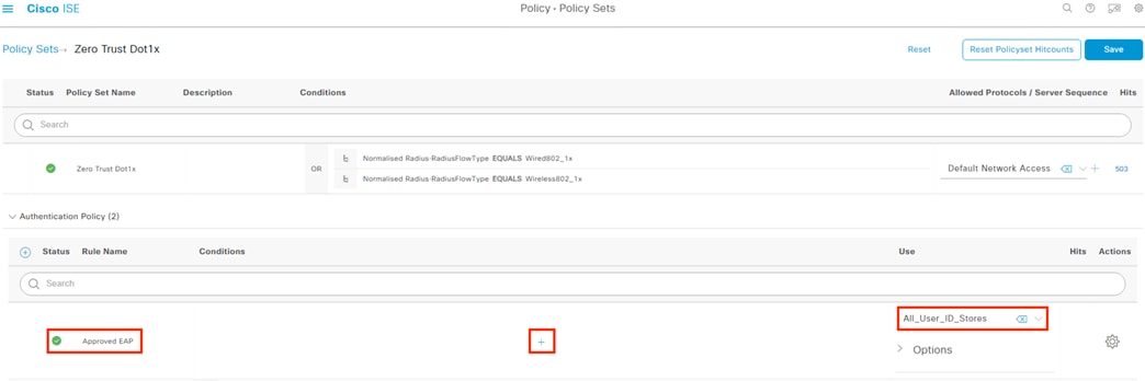
Step 3. Click to add an attribute.
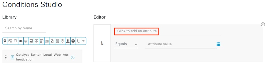
Step 4. Select Protocol (highlighted in blue), set the Dictionary to Network Access, and select the EapAuthentication attribute.
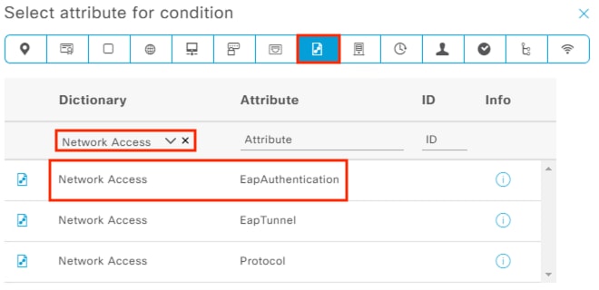
Step 5. With the Network Access-EapAuthentication criteria set, click the drop-down and select EAP-TLS (this will match our NAM configuration for machine and user auth).
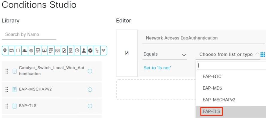
Step 6. Click the New option.
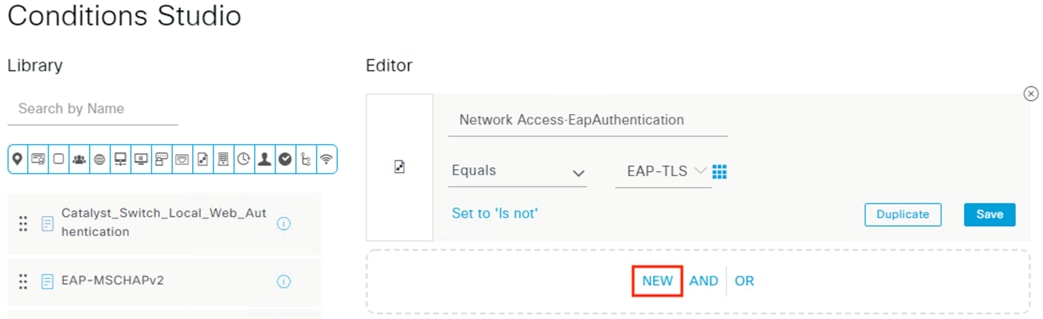
Step 7. Click to add an attribute.
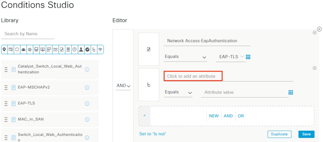
Step 8. As with the prior step, set the Dictionary to Network Access and the Attribute to EapAuthentication.
Step 9. Set the condition to OR and select EAP-MSCHAPv2 for this EapAuthentication (this will allow untrusted devices that do not have the NAM installed to pass Authentication, while restricting less secure protocols).
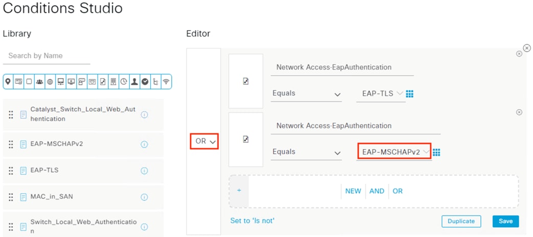
Step 10. Scroll down to the bottom of the page and click Use. Verify the rule details and set the Default rule to DenyAccess. Click Save.
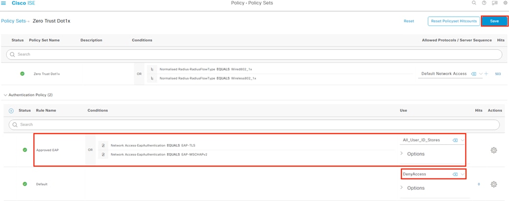
ISE: Create Authorization Policy Rules
Expand the Authorization Policy – Global Exceptions section and note that there is a default rule from the ANC Policy that sets a Quarantine match to Deny Access. This is the mechanism that will block endpoints that are quarantined in Secure Analytics using the ANC feature.
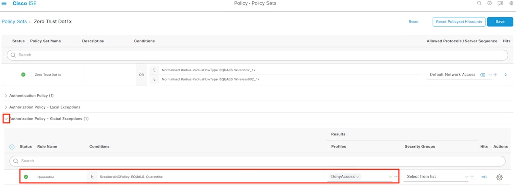
Step 1. Expand the Authorization Policy and click the + icon to create a new rule.
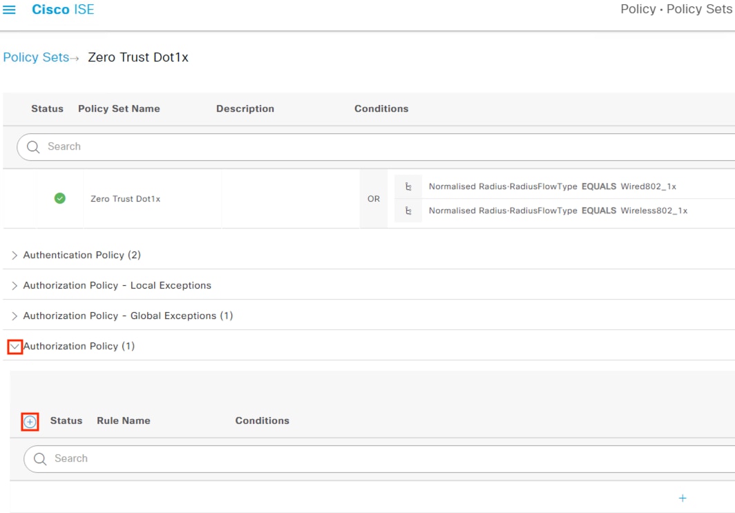
Step 2. Name the rule and click the + icon under the Conditions column to modify the rule criteria.
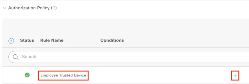
Step 3. Click to add an attribute.
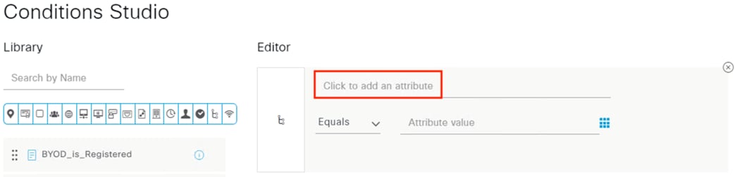
Step 4. Select the Protocol set, select Network Access under Dictionary, then click the EapTunnel attribute.
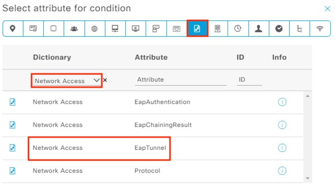
Step 5. Click the dropdown and select EAP-FAST. This will match the 802.1X connection initiated by the NAM installation.
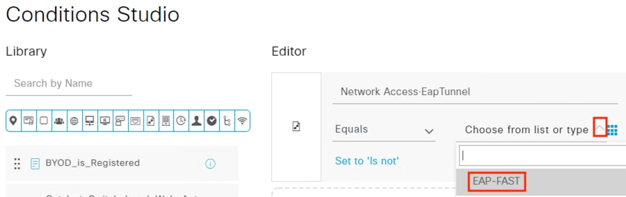
Step 6. Click on NEW.
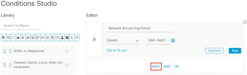
Step 7. Click to add an attribute.
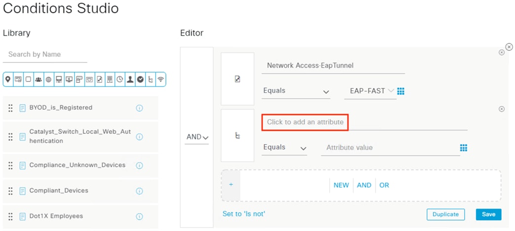
Step 8. Select Protocol, filter the Dictionary by Network Access, and click on EapChainingResult.
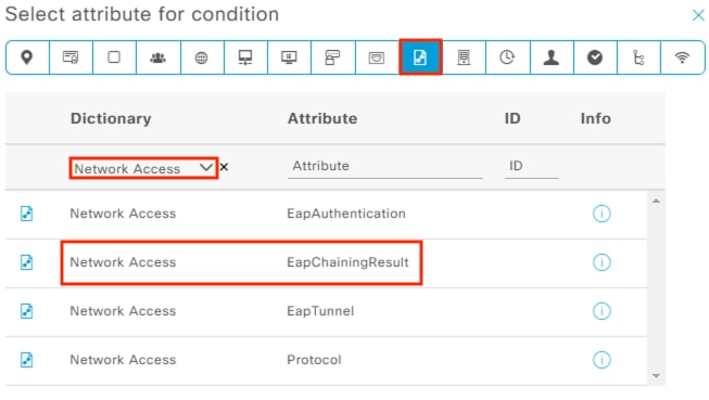
Step 9. Click the drop-down and select ‘User and machine both succeeded’. This will restrict rule matches to only 802.1X attempts that submit both a machine and user auth and pass both.
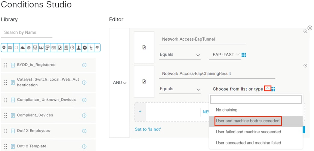
Step 10. Click New again.
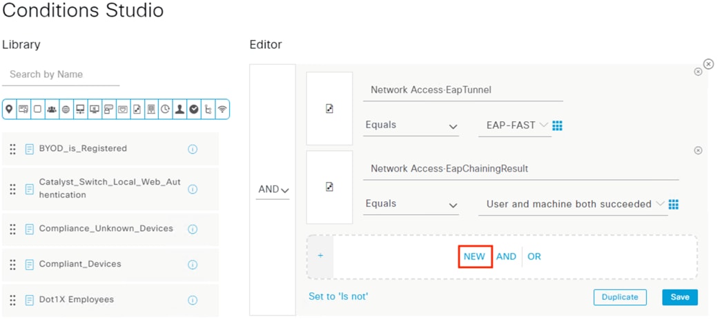
Step 11. Select the Identity category and click on the AD join point under Dictionary and ExternalGroups as the Attribute.
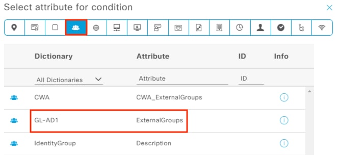
Step 12. Click the drop-down and select the Employee group.
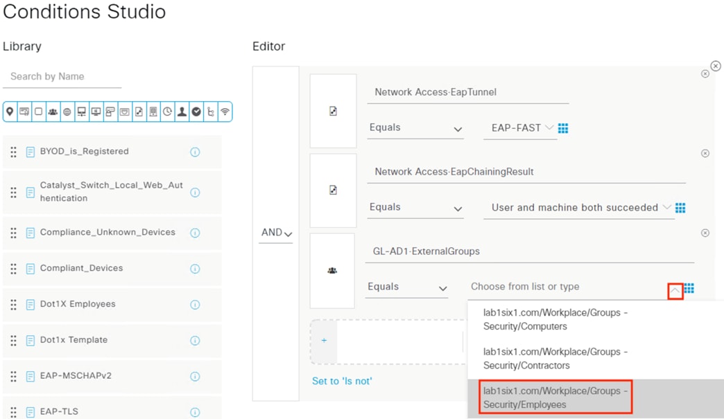
Step 13. Scroll down and click Use. Verify the Conditions, set the Profile to PermitAccess, and set the Security Group to Employee_Trusted_Device. Finally, click the gear icon and select ‘Duplicate below’.
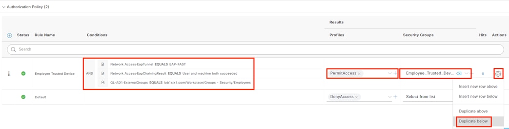
Step 14. Click the Conditions of the duplicate rule to edit.
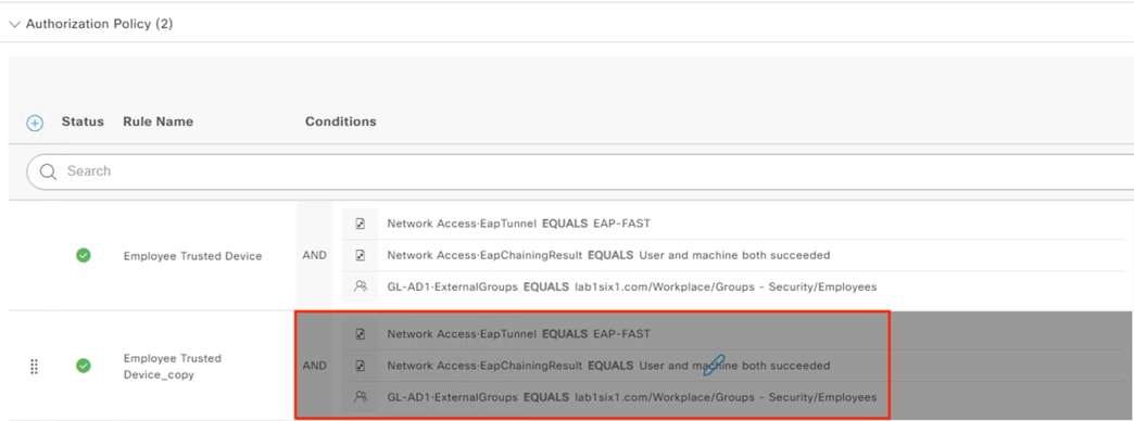
Step 15. Click the x to remove the Employees group.
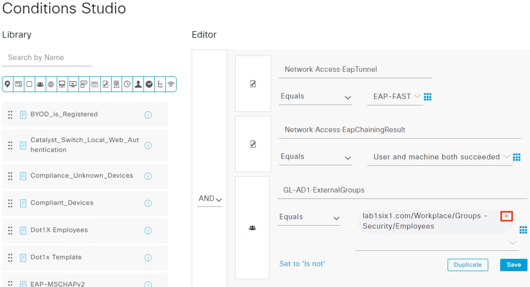
Step 16. Click the drop-down and select the Contractors group. This will perform a Trusted Device check against users in the Contractor group.
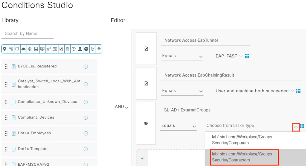
Step 17. Scroll down and click Use. Change the rule name to Contractor Trusted Device and change the Security Group to Contractor_Trusted_Device. Click Save.
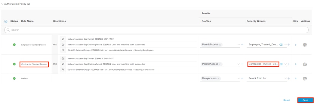
Step 18. Create two new rules that use only the AD group criteria and assign the Untrusted SGTs to Employees and Contractors. These should be placed below the Trusted rules so that users are evaluated against the Trusted rules first, then drop down to the Untrusted rules if they fail the Trusted rule checks.
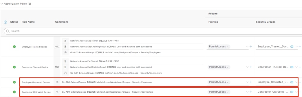
Step 19. Create a new rule for the Machine authentication. This will be the same format as the Untrusted Device rules, but it will perform a check against an AD group for computers rather than users.
The final policy configuration is shown below. Note that the policy order should be Trusted Devices at the top and Machine Authentication at the bottom. Because ISE policies are evaluated top to bottom, this allows us to match a login to a Trusted User if that criteria is met, then an Untrusted User if that criteria is met, and then finally a Machine Authentication if no user login is provided. If the login attempt is not from a user or machine in an accepted AD group, then the Default of DenyAccess is applied.
Step 20. After reviewing the policy details, click Save.
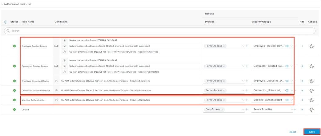
ISE: Enable Guest Wireless Rules
The Default policy has two rules for Guest Wireless access that we’ll use, with one modification.
Step 1. Return to the Policy Sets page and view the Default policy.
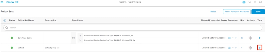
Step 2. Expand the Authorization Policy and locate the rules for Wi-Fi_Guest_Access and Wi-Fi_Redirect_to_Guest_Login. Enable both rules and set the Security Group for Wi-Fi_Redirect_to_Guest_Login to Guest_Registration.
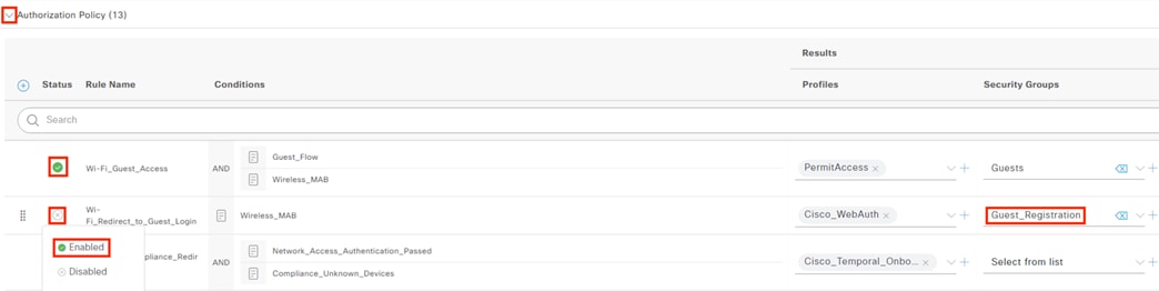
Step 3. Click Save when finished.
Secure Firewall Access Control with Dynamic SGT
We previously configured Secure Firewall to receive Dynamic SGT information from ISE via pxGrid, and to receive destination SGT mappings via SXP domain. Now that we have end users successfully authenticating via 802.1X and receiving SGT assignments upon login, we can use both source and destination SGT assignments in Secure Firewall rules. The example rules given below are for outbound connections leaving a branch without a local DNS or ISE server destined for applications hosted at a data center over SD-WAN.
We’ll create rules to allow the following connections.
1. Employees with the Trusted Device SGT can connect to an internal case portal. Because the portal contains sensitive customer information, only users with trusted devices are allowed access.
2. Users with the Contractor Untrusted Device SGT can connect to an internal Sock Shop app that offers premium, discounted socks to users regardless of device trust.

3. Allow guests to access the internet regardless of device trust.
Supplementary rules to permit DNS resolution for the internal apps and to allow prospective guest users to access an ISE registration portal are also covered.
While these rules are intentionally overfitted to their respective allowed users, they serve as clear examples of applying least privilege to different connections. The example rules below are all configured with an allow by exception, deny by default philosophy.
Secure Firewall: Create Access Control Policy
Step 1. From the FMC GUI, navigate to Policies à Access Control.
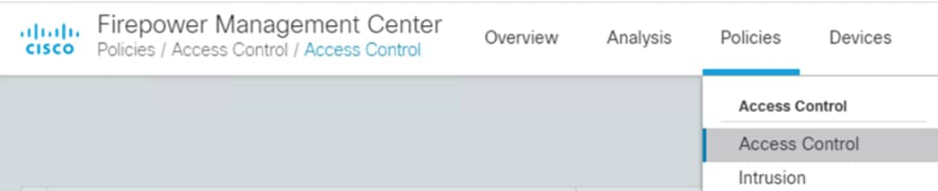
Step 2. Either edit a currently applied policy or click the New Policy button to create one.
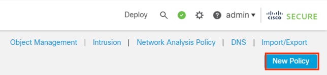
Step 3. Enter a name for the policy and assign a Secure Firewall device as the target using the Add to Policy button. As a best practice this guide uses the ‘Block all traffic’ option as the Default Action, meaning that any traffic that is not allowed by a rule will be blocked (implicit deny, permit by exception). Click Save.
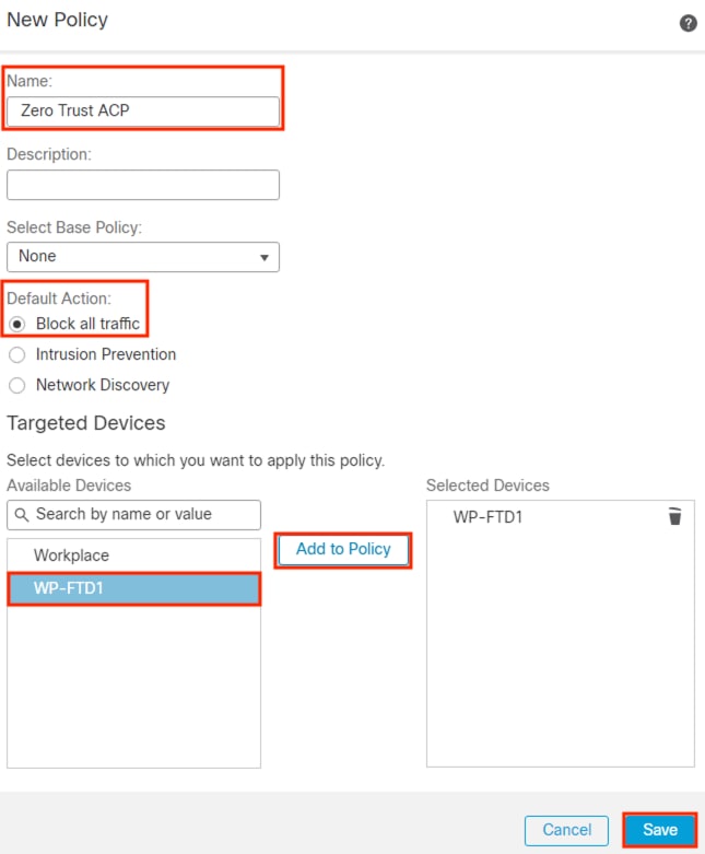
Secure Firewall: Rule Creation Walkthrough
Step 1. From the edited or newly created policy, click the Add Rule button. Note that the following screenshots use the new UI layout set by the toggle switch highlighted below.
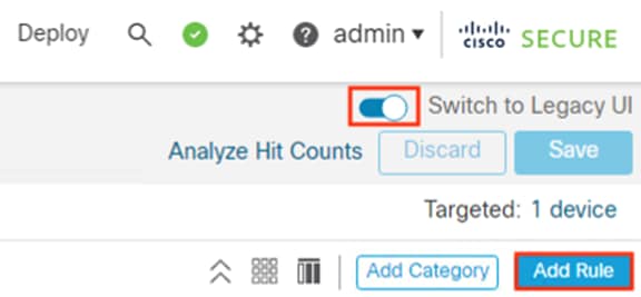
Step 2. Enter a name for the rule and select where in the policy to Insert it.
Step 3. On the left side, set the action to Allow so that matching connections will be permitted with subsequent inspection.
Step 4. Set the Intrusion Policy (the default Balanced policy is shown below)
Step 5. Set a default or custom Variable Set
Step 6. Select a File Policy (for steps to create a file policy and integrate it with Secure Malware Analytics Cloud, please see Appendix D)
Step 7. It is recommended to enable beginning of connection logging for initial testing, after which logging can be switched to end of connection to collect more connection details. Alternatively, both beginning and end of connection logging can be enabled if storage of duplicate logs is not a concern.
Step 8. Finally, click the middle of the page to add object and group criteria.
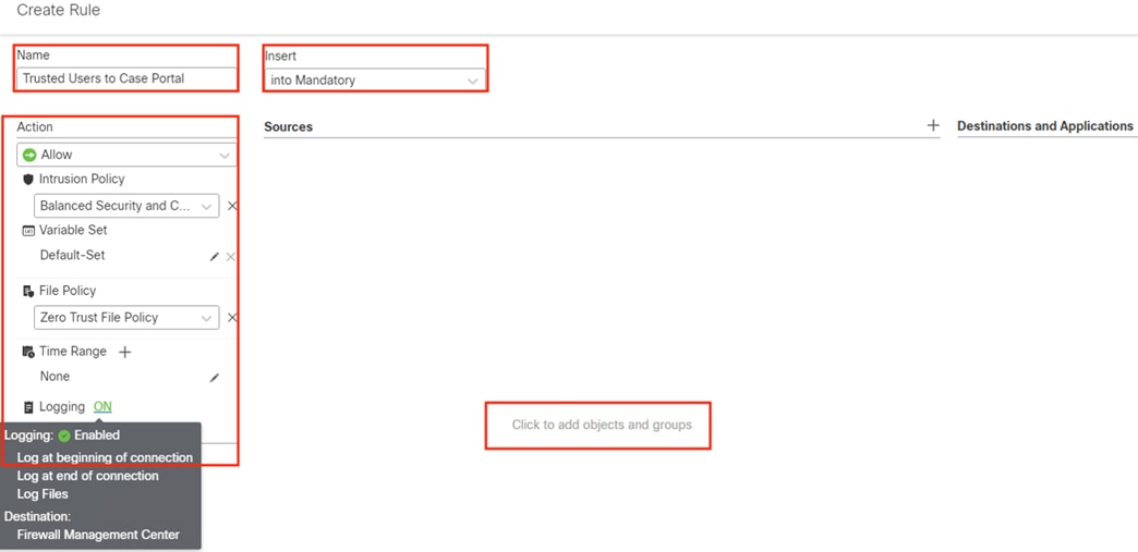
The Network page loads first by default. We can follow two different philosophies for networks when using SGTs:
1. Specify network criteria in addition to SGTs for firewall policy auditing purposes
2. Utilize SGTs exclusively to reduce network object maintenance and overhead across the firewall deployment
For this example, we will supplement our SGT criteria by also adding a source object that defines the host subnet allocated to user endpoints. The effect of this is an AND condition—the firewall rule will match a session that is sourced from an IP within the host subnet AND which also has a designated SGT attached to the packet, confirming a successful auth and device validation. We’ll leave the destination network blank and rely strictly on destination SGT attributes from ISE to reduce IP groups maintenance and use ISE as a single source of truth.
The screenshot below shows the action of searching for a premade network range object and adding it as Source criteria.
Step 9. Alternatively, new objects can be created by clicking the Create Network Object link in the lower left. When finished, click the Zone tab.
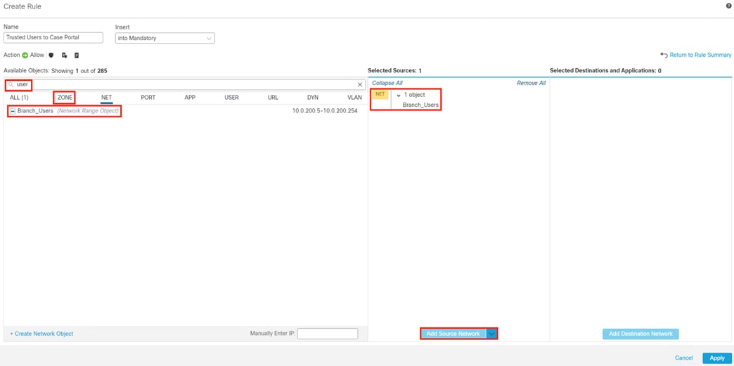
Security Zones are mapped to firewall interfaces and serve as a mechanism to specify traffic flow for a rule.
Step 10. In this example, we want to allow end users to connect to the data center over SD-WAN, so we will set the Workstations Security Zone (which is connected to the access switch) as the source, and the SD-WAN Security Zone (which is connected to the edge router) as the destination.
Step 11. When finished, click on the Port tab.
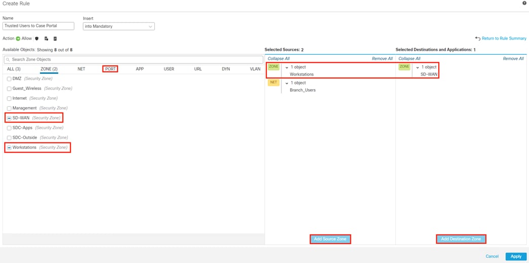
Step 12. Search for 443 and add the HTTPS TCP/443 object as a destination port (or use the Create Port Object link in the lower left, if needed). The source port for HTTPS connections is drawn from the ephemeral port range, and these are typically left as ‘any’ criteria in practice. However, a port range of 1024-65535 can be added for the Source port if desired.
Step 13. When finished, click on App.
Note: HTTPS destination ports other than 443 can also be added here, such as 8443.
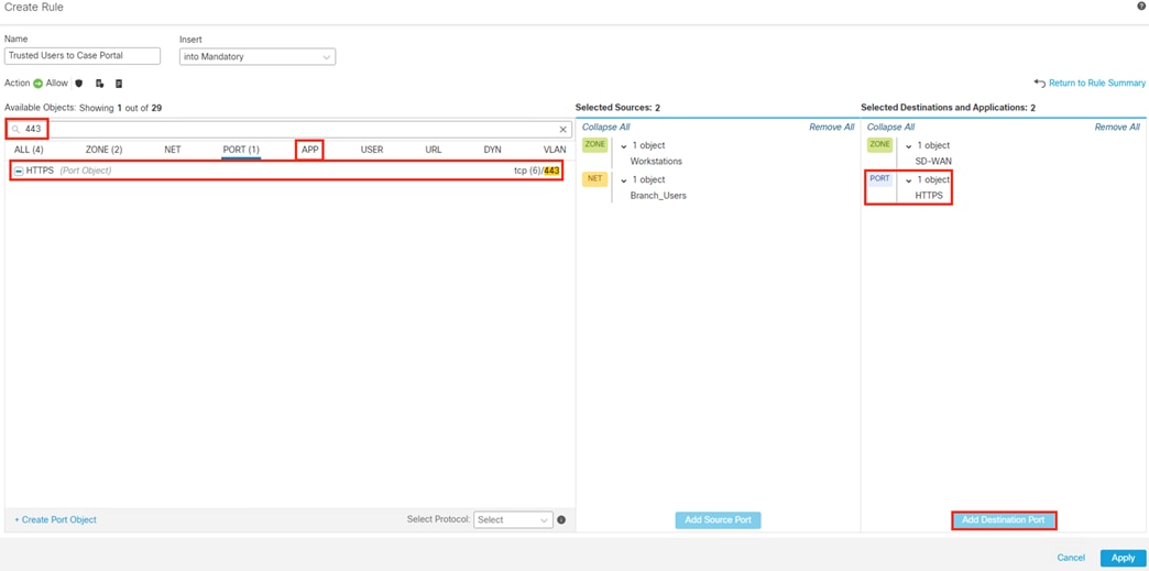
Step 14. From the Application page, search for HTTPS and add the HTTPS application to the Destination column.
Step 15. When finished, click on the URL tab.
Note: While there is some redundancy to specifying destination port 443 and HTTPS application detection in the same rule, there are some beneficial security outcomes in doing so. Specifying only port 443 will allow protocols other than HTTPS to match the rule and be allowed, which isn’t our intent here. Alternatively, specifying only HTTPS with no destination port also has a drawback. Application detection typically relies on a unique packet or string for identification, and for a TCP session this will occur at least after the three-way handshake and perhaps even later in the session. Specifying both 443 and HTTPS application tells the firewall to only wait for HTTPS application detection for sessions that have destination port 443, and to deny the session if the port 443 connection turns out to be something other than HTTPS (for an HTTPS session the earliest that application detection can occur is on the 4th packet, the Client Hello).
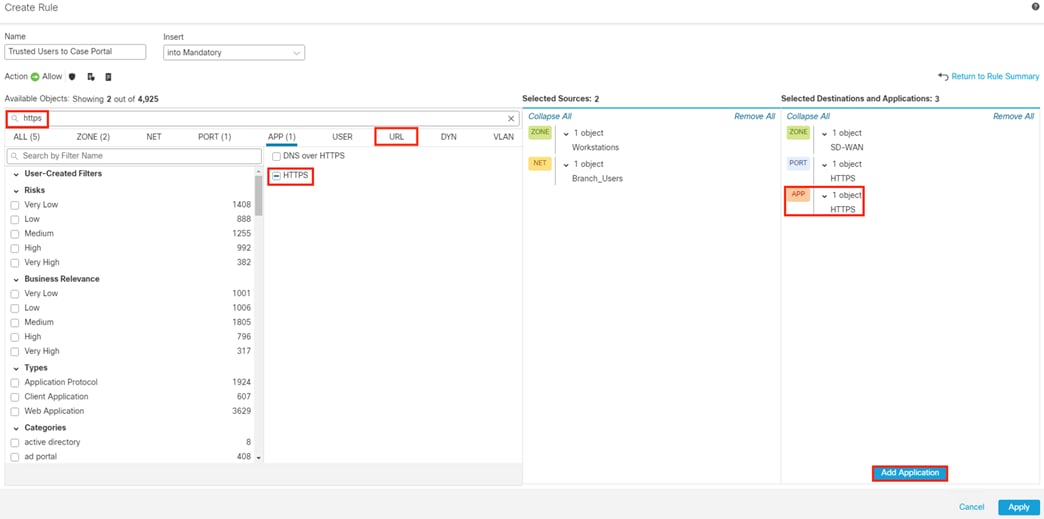
Step 16. From the URL page, enter the URL and click the Add URL button to add it to the Destination column (or use an object, if preferred). The example below shows a case portal address. URL matching is done via string match, and we want to be as specific as possible without leaving out any wanted matches. For example, if we wanted to match both HTTPS and HTTP, we could remove the https:// from the start of the URL string, but that isn’t our intent here. When finished, click on the Dynamic Attributes tab.
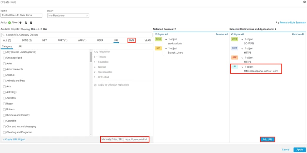
Step 17. Use the search bar to find the Dynamic SGTs from ISE and add them to the Source and Destination columns. For this example, we use source of Employee_Trusted_Device and Destination of DC_Application_Servers. When finished, click Apply.
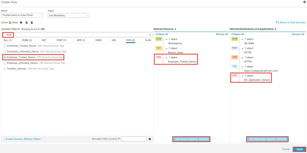
Step 18. Review the rule, then click Save.
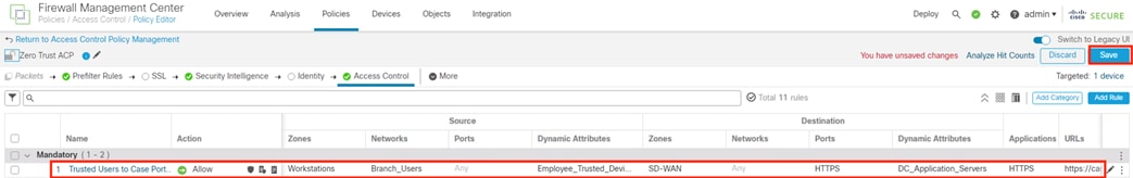
Secure Firewall: Complete Access Control Policy Rule Creation
Step 1. Click Add Rule to configure additional rules and click Save when finished. Complete criteria for each rule are shown below.
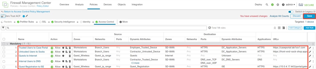
Notes on the criteria used in each of the above rules:
1. Configuration and logic of the first rule were given in the prior section
2. The second rule allows users who were assigned the Contractor_Untrusted_Device SGT during the ISE AA process to access a sock-shop URL hosted by the application servers mapped to the DC_Application_Servers SGT. This rule is very similar to rule 1, with the only differences being selection of a different source SGT and destination URL.
3. The third rule permits users assigned the Guests SGT during the ISE AA process to access destinations that have the Unknown SGT, which will match any IP space not used by the internal network. Zones are used to force the traffic path of Guest_Wireless to Internet—while the configuration is not shown in this guide, the separation of an Outside firewall interface into internet and SD-WAN Security Zones could be accomplished via a logical sub-interface and separate VRF, with corresponding sub-interface and VRF on the edge router. Alternatively, both SD-WAN and internet traffic can be sent to a single edge router interface, with routing decisions left to the router. The rest of the rule is left intentionally broad, as the intention is to provide general web access to guest users without restriction. However, the Intrusion Policy has been enabled to provide some visibility and protection against the possibility of users launching malicious activity from the company IP space. The File policy has been disabled to reduce firewall resource overhead on guest connections.
4. The fourth rule allows the four Contractor and Employee SGTs to access internal DNS servers over TCP and UDP ports. This rule allows end users to perform name resolution for the URLs allowed in rules one and two. As with rules one and two, a destination SGT is specified, in this case corresponding to the DC_DNS_Servers static SGT assignment performed in the Configure ISE Security Groups and Static Mapping section.
5. The fifth rule permits the connection for a prospective guest user to connect to ISE and complete the Guest Portal process. The allowed URL is in the default format used by the Cisco_WebAuth profile, which was used in the ISE: Enable Guest Wireless Rules section. Because the connection is HTTPS, matching port and application criteria is used. Note that decryption capabilities are needed to match on path beyond the URL (e.g. /portal/gateway).
Step 2. With the policy saved, click Deploy.
Step 3. Click the Deploy button for the firewall associated with the saved Access Control Policy from this section.
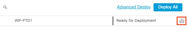
Step 4. Verify that the Deployment completes successfully.
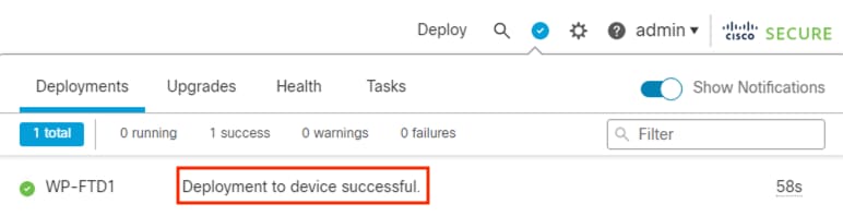
Validation and verification steps are given throughout this guide for individual sections and configurations. The tests below incorporate multiple areas of integration and should be performed when all areas of configuration are complete.
ISE: Validate Machine and User 802.1X Authentication and Authorization
In the ISE Authorization Policy section we created five rules to track AA for Employees, Contractors, and device posture. We’ll test the most complex sequence of Machine AA à Trusted Employee/Contractor + Machine AA in this section.
To start, we want to force a new Machine AA attempt from a Trusted device. The easiest way to force a new Machine AA attempt is to have the user sign out and then sign back in again (note: a user resuming a locked session won’t trigger a new Machine AA attempt). After the endpoint signs on, from ISE navigate to Operations à RADIUS à Live Logs.
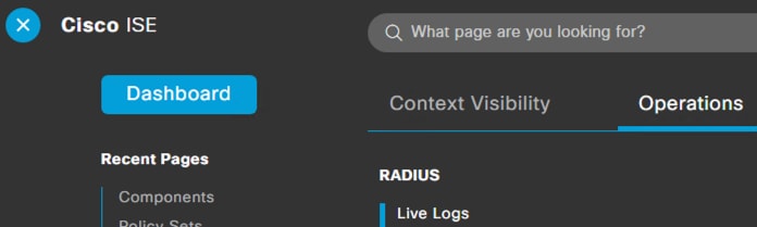
ISE RADIUS logs show a sequence of machine auth (host/Desktop in the screenshot below) followed by machine + user auth (lee,host/Desktop in the screenshot below), both from the same Endpoint ID. Click the view icon under the Details column to view the machine auth report.
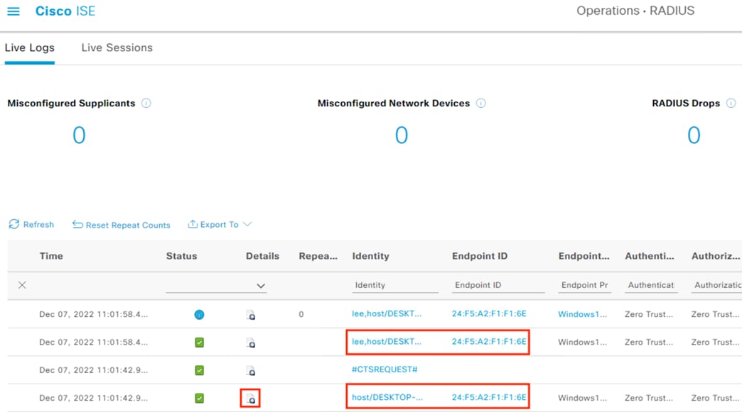
Machine Authentication and Authorization
The Overview section of the report shows the username as the desktop name of the endpoint, which is expected for machine authentication.
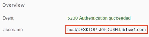
The Username field in the above screenshot matches the name of the issued computer certificate on the endpoint.
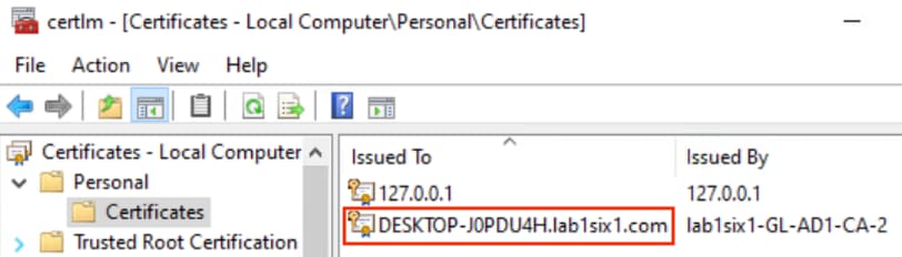
The Authentication and Authorization fields in the overview section also match the expected AA policy rules we configured previously, with result of Permit Access.
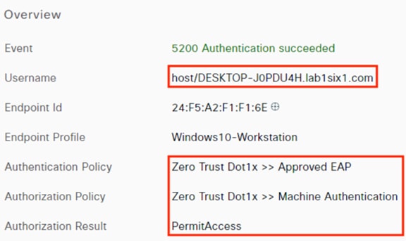
Reviewing the Authentication Details section of the report, we can see that the Authentication Protocol is the EAP-FAST configured on the NAM install, and the Machine_Authenticated SGT has been assigned.
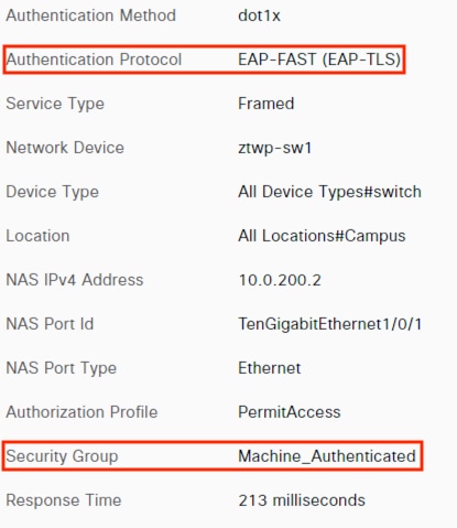
The Other Attributes section shows an EapChainingResult of ‘User failed and machine succeeded’—this is expected, as the host has submitted machine credentials via certificate but no user credentials. We also see that matched AD group is the Computers group, not a user group.
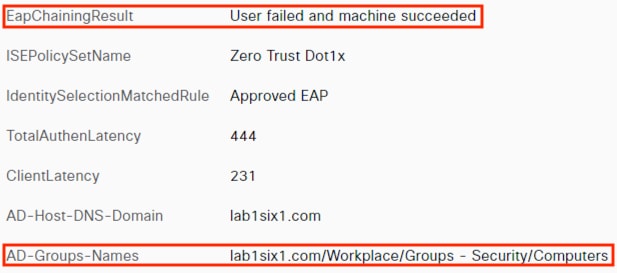
Going through a few points of the Steps section of the report, after initial EAP-FAST and TLS negotiation we see EAP chaining begin for the user type, which the client rejects and prompts for machine type instead.
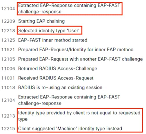
Later logs show the extraction and evaluation of the client certificate.
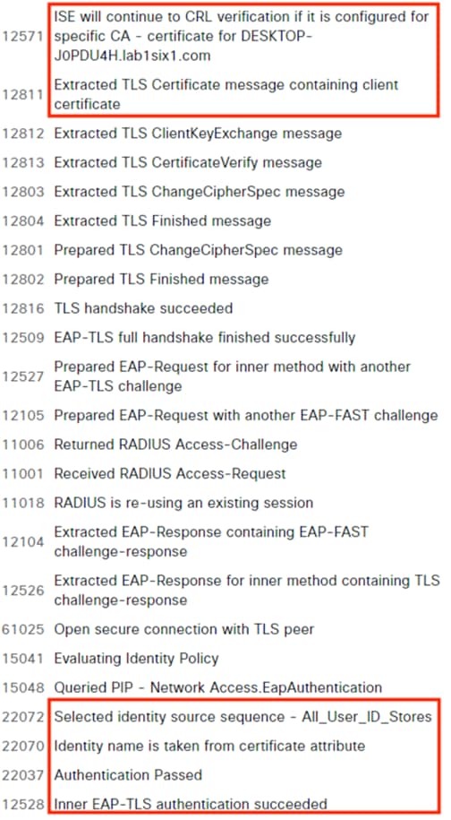
A check of the machine is also performed against Active Directory, which succeeds.
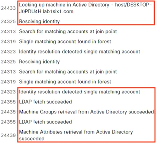
Return to the Live Log page and drill down on the user + machine log.
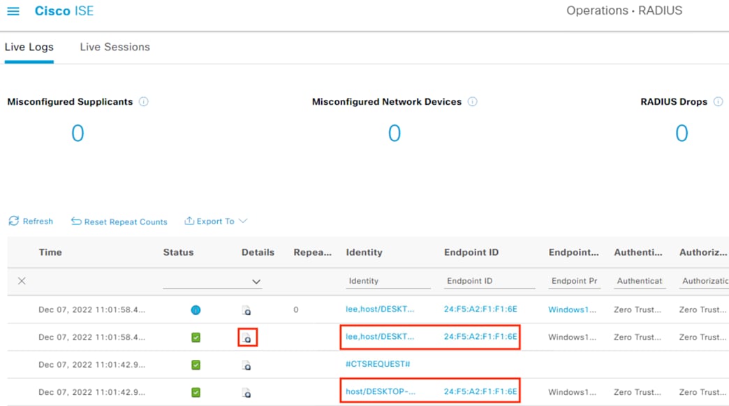
Machine + User Authentication and Authorization
The Overview section is like the machine auth results, with two notable differences—the username (lee) appears before the host details, and the Authorization Policy match is the Employee Trusted Device rule.
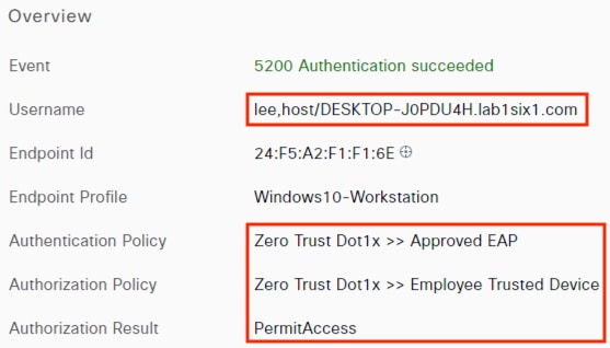
In the Authentication Details we see that both EAP-TLS and EAP-MSCHAPv2 were used as inner methods by EAP-FAST, and the assigned SGT is Employee_Trusted_Device.
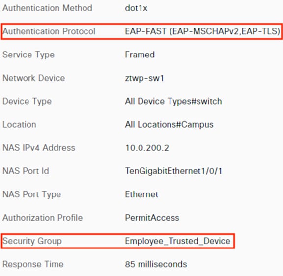
Reviewing additional Authentication Details, we see that the EapChainingResult is now successful for both user and machine, and AD queries were performed for both the user and machine.
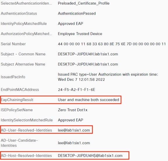
Reviewing the Steps section, the client this time proceeds with the user auth rather than suggesting machine auth; the user auth succeeds.
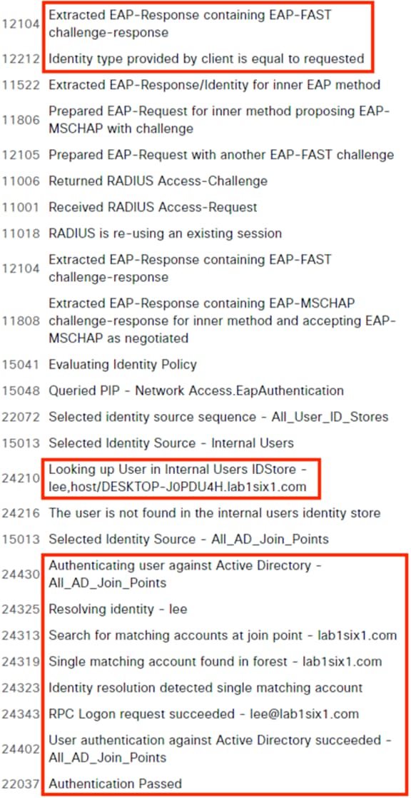
A check of the machine against AD is then performed.
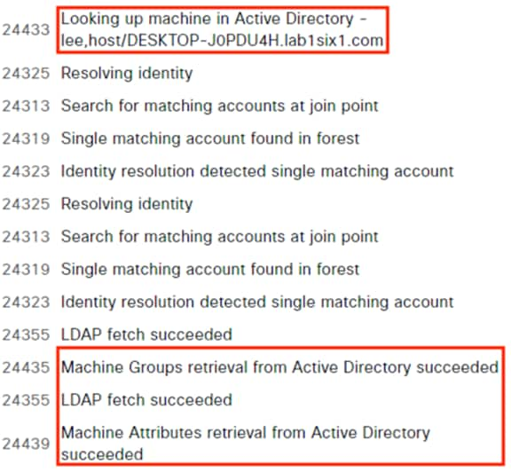
Secure Firewall: Validate Access Control with SGTs
With the rules configured and successfully applied, use an endpoint to generate traffic that matches one of the allow rules. Once the traffic has been generated, Navigate to Analysis à Connections à Events, then click on Edit Search.
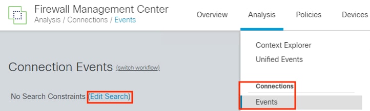
For this example, we’ll search for a DNS query to our caseportal.lab1six1.com application server. Click the Networking category on the left side, enter search criteria in the DNS Query field, then click Search.
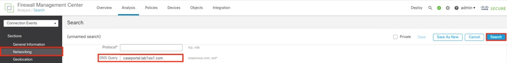
The default search results show us most of the fields we’d expect for this connection. Note that there are two connection events, one that has a Last Packet field and another that only has a First Packet field. These two events are due to us checking both beginning and ending Connection Event logging. In this case, the beginning log was generated when the DNS request was seen, then the ending log was generated after the DNS response was seen and Secure Firewall detected that the DNS session was complete.
Click on Table View of Connection Events for more details.
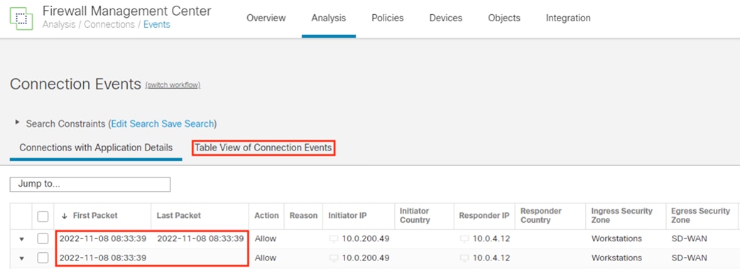
The Table View of Connection Events has many columns. We only need some of them to confirm a solid match of our expected Access Rule, and it can be helpful to collapse those useful columns into one view. Click the ‘x’ on any column, then uncheck any columns that are not needed. Click Apply. Note: disabling columns is a temporary change and will reset when the FMC session ends.
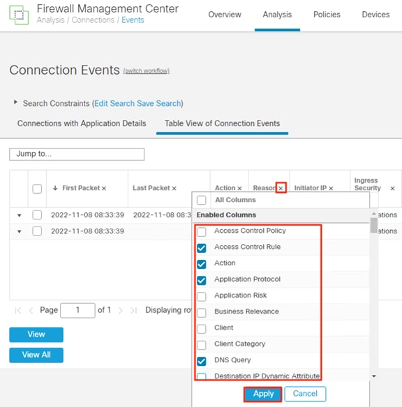
From the Table View we can confirm that the traffic matched the previously configured DNS rule, that the DNS Application was successfully detected for the port 53 traffic, and that the Source and Destination SGTs are both correct for the flow. Also note that our End of Connection event has an additional Responder Packet and associated Responder Bytes—by waiting until the end of the connection (DNS Request + DNS Response) to generate an event, additional packet information was collected.
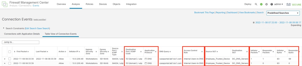
ISE and Secure Analytics: Validate User Quarantine
We can test a quarantine block by manually setting an authenticated user to quarantine in Secure Analytics and then re-attempting a connection.
Step 1. From Secure Analytics, navigate to Analyze à Flow Search.
The ANC quarantine action is performed from the host page, so we’ll search for the source IP seen in the last section.
Step 2. Enter the IP address, change the time window if necessary, then click Search.
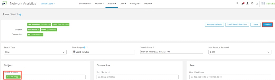
Step 3. Click the IP address in any flow event.
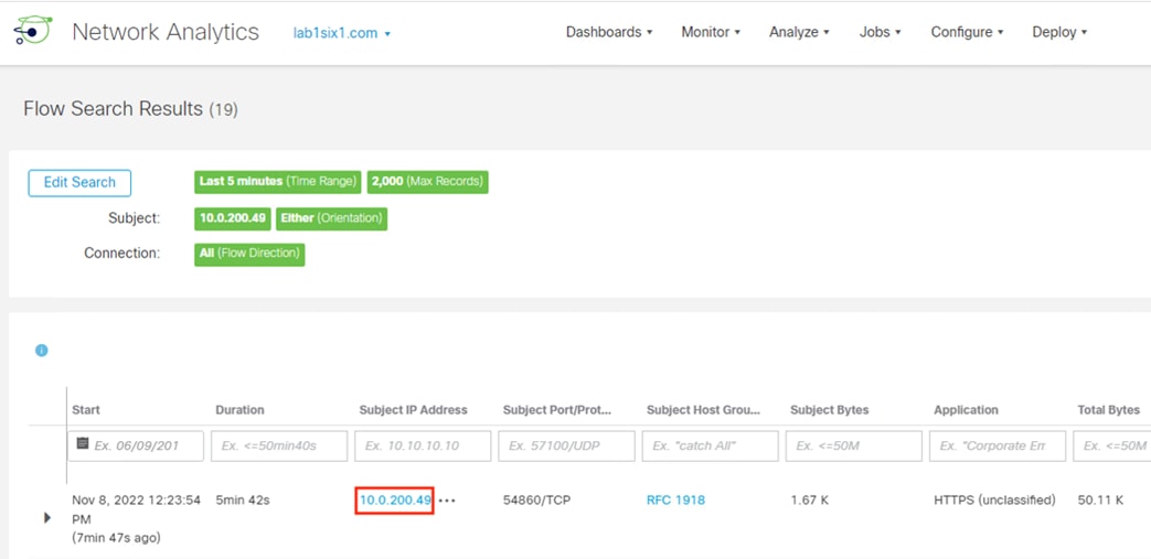
Step 4. Scroll down the page to verify the target user is still logged into the host, then click Edit next to ISE ANC Policy.
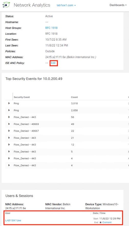
Step 5. Reconfirm the username, select Quarantine from the ANC Policy dropdown, then click Save.
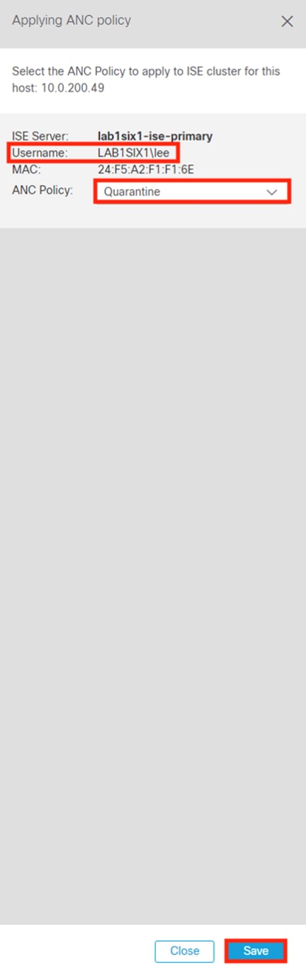
Generate some traffic on the quarantined user’s endpoint. The expected result is that all traffic fails.
Step 6. From ISE, navigate to Operations à RADIUS à Live Logs.
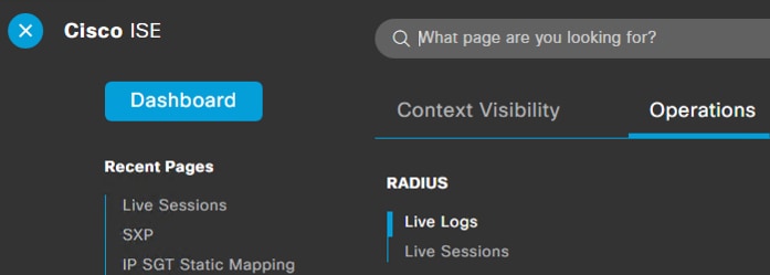
Step 7. Confirm an auth event for the quarantined user with result DenyAccess. Click on the details option.
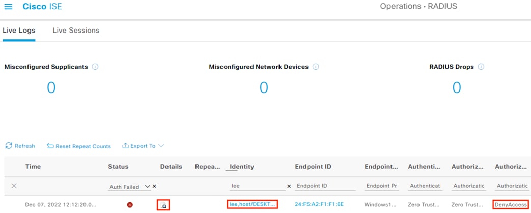
Step 8. Review the Overview details. The connection should match the ANC Quarantine rule, which has the result DenyAccess.
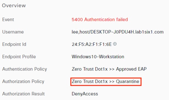
The Steps section provides a detailed breakdown of the ANC evaluation.
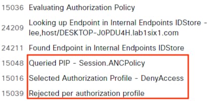
Step 9. Return to Secure Analytics. To restore access to the quarantined user, navigate to Monitor à ISE ANC Assignments.
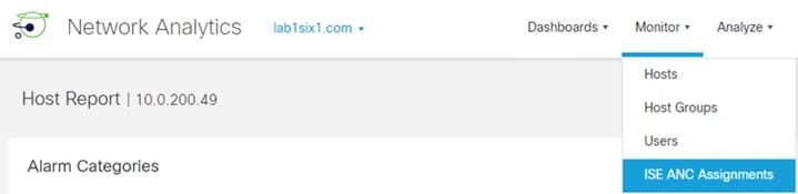
Step 10. Click the ellipses underneath the Assign ANC Policy column and select None.
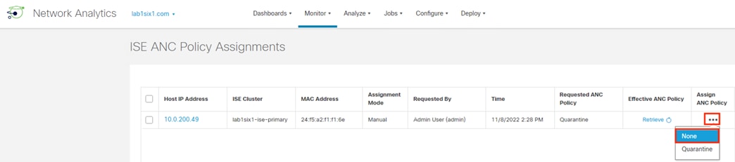
Step 11. Reload the page and confirm that the quarantine entry is removed.
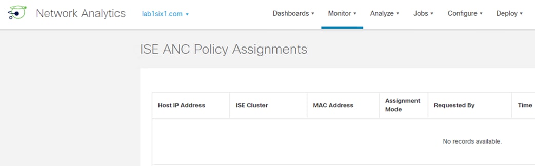
The method of quarantine used in this guide results in an 802.1X attempt with result of DenyAccess, so there is not an active 802.1X session for the host after the quarantine is removed. In Operations à RADIUS à Live Sessions, ISE will show the Session Status as Terminated.
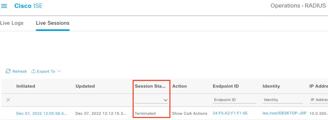
There are no CoA actions available for a terminated session.
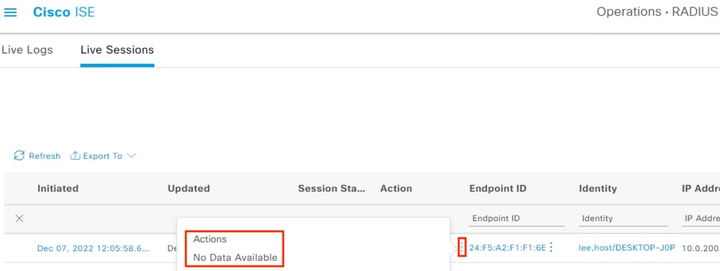
The end user will need to initiate a new login event to restore access.
| Acronym |
Definition |
| ACP |
Access Control Policy |
| AVC |
Application Visibility and Control |
| BYOD |
Bring Your Own Device |
| CA |
Certificate Authority |
| CN |
Common Name |
| CoA |
Change of Authorization |
| CSR |
Certificate Service Request |
| CTB |
Cisco Telemetry Broker |
| CTS |
Cisco TrustSec |
| DC |
Data Center |
| DNG |
Duo Network Gateway |
| DNS |
Domain Name System |
| FMC |
Firewall Management Center |
| FQDN |
Fully Qualified Domain Name |
| Firepower Threat Defense |
|
| GUI |
Graphical User Interface |
| HTTPS |
Hypertext Transfer Protocol Secure |
| ISE |
Identity Services Engine |
| MAR |
Machine Access Restriction |
| MDM |
Mobile Device Management |
| MFA |
Multi-Factor Authentication |
| MnT |
ISE node with Monitoring designation |
| MSRPC |
Microsoft Remote Procedure Call |
| NGFW |
Next Generation FireWall |
| OS |
Operating System |
| PAC |
Protected Access Credential |
| RADIUS |
Remote Authentication Dial-In User Service |
| RBAC |
Role Based Access Control |
| SAN |
Subject Alternative Name |
| SD-WAN |
Software Defined Wide Area Network |
| SOC |
Security Operations Center |
| SG |
Security Group |
| SGT |
Security Group Tag |
| SGACL |
Security Group Access Control List |
| SXP |
SGT Exchange Protocol |
| TLS |
Transport Layer Security |
| URL |
Uniform Resource Locator |
| WMI |
Windows Management Instrumentation |
Appendix B – Software Versions
| Product |
Platform |
Version |
| Cisco Catalyst 9300 |
Hardware Switch |
17.9.1 |
| Cisco Identity Services Engine |
Virtual Machine |
3.1 |
| Cisco Firepower Threat Defense 4140 |
Hardware Firewall |
7.2 |
| Cisco Secure Firewall Management Center |
Virtual Machine |
7.2 |
| Cisco Secure Network Analytics Flow Collector |
Virtual Machine |
7.4 |
| Cisco Secure Network Analytics Management Center |
Virtual Machine |
7.4 |
| Cisco Telemetry Broker Manager |
Virtual Machine |
1.2.3 |
| Cisco Telemetry Broker Node |
Virtual Machine |
1.2.3 |
Appendix C – Secure Malware Analytics Integration
Secure Malware Analytics is a cloud and on-prem malware sandbox that performs dynamic analysis on submitted files. In this guide, we configure Secure Firewall to automatically send files to Secure Malware Analytics for sandbox analysis. Note: these steps require a Secure Malware Analytics cloud account.
Step 1. Navigate to Policies à Malware & File.
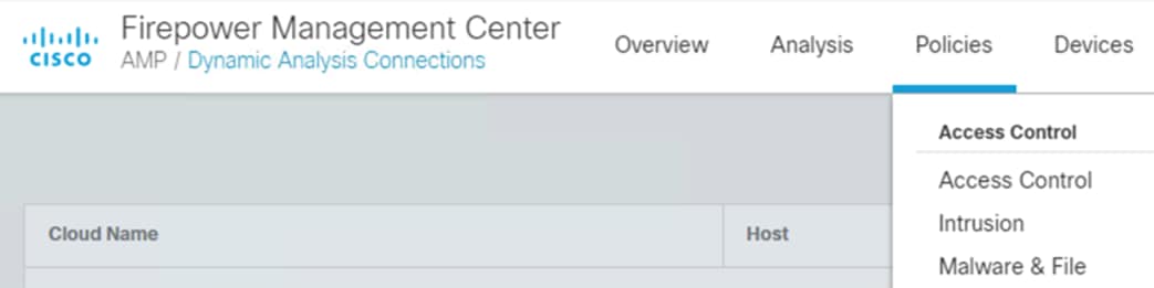
Step 2. Clink on New File Policy.

Step 3. Enter a name for the File Policy, and a description if desired. Click Save.
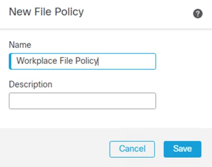
Step 4. Click on Add Rule.
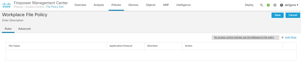
Step 5. Set the Action to Block Malware, which will block the final packet of an identified malware file, resulting in transfer failure.
Step 6. Check the box for Dynamic Analysis so that eligible files can be submitted to Secure Malware Analytics for further analysis.
Step 7. Add file categories for malware inspection—for this example, we’ve added the file types that are eligible for Dynamic Analysis. Set the other options as desired.
Step 8. Click Save.
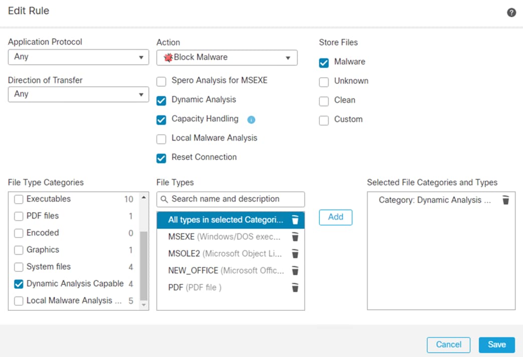
Step 9. Click Save again to save the File Policy.
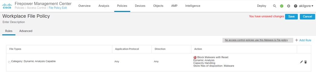
The File Policy will be associated to an Access Control Policy in the Creating Access Control Policies section.
Associate FMC to Secure Malware Analytics Cloud
Step 1. Navigate to AMP à Dynamic Analysis Connections.
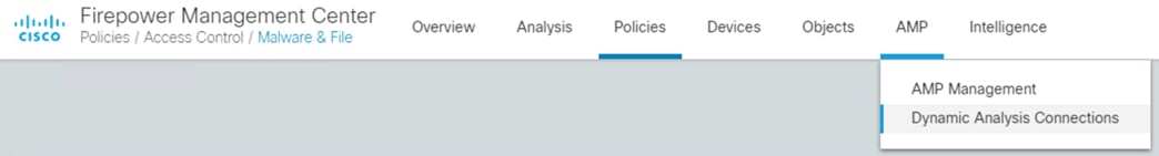
The cloud connection to Secure Malware Analytics is preconfigured, but you’ll need to associate it to a cloud account to view details of sandbox analysis in the Malware Analytics cloud portal.
Step 2. Click the Associate button (chain icon) on the right side.
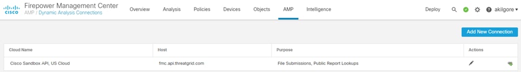
Step 3. Click Yes on the prompt.
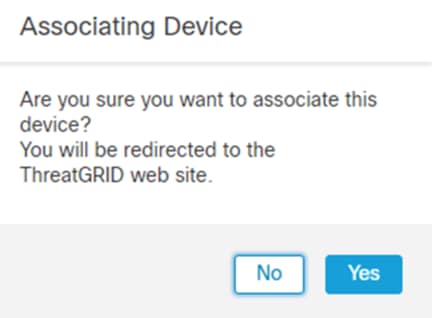
Step 4. Enter credentials for the online portal and click Log In.
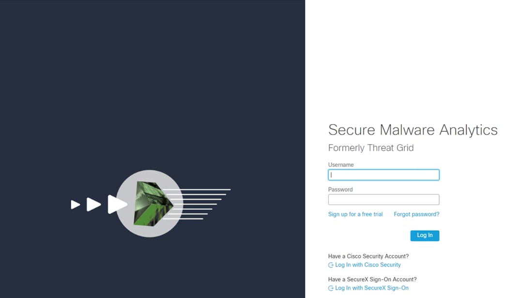
Step 5. Click the green Submit button to associate (scroll to the right to see the full association ID).
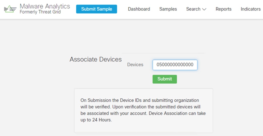
Association may take up to 24 hours for the public cloud.
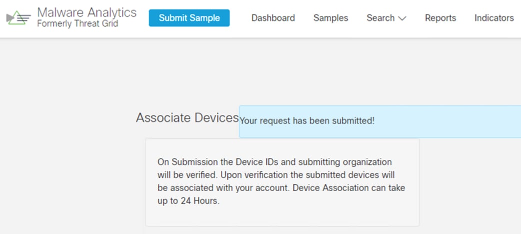
● Cisco Zero Trust Architecture Guide
● Cisco Zero Trust: User and Device Security Design Guide
● Cisco SAFE Certificate Management Design Guide
If you have feedback on this design guide or any of the Cisco Security design guides, please send an email to ask-security-cvd@cisco.com.