Secure Data Center – Cisco ACI, Secure Firewall, and Secure ADC Design Guide
Available Languages
Bias-Free Language
The documentation set for this product strives to use bias-free language. For the purposes of this documentation set, bias-free is defined as language that does not imply discrimination based on age, disability, gender, racial identity, ethnic identity, sexual orientation, socioeconomic status, and intersectionality. Exceptions may be present in the documentation due to language that is hardcoded in the user interfaces of the product software, language used based on RFP documentation, or language that is used by a referenced third-party product. Learn more about how Cisco is using Inclusive Language.
This design guide details the secure data center solution based on the Cisco Application Center Infrastructure (ACI). The Cisco Secure Firewall and Cisco Secure Application Deliver Controller (ADC) solutions are used to secure access to the workloads in an ACI data center.
The target audience for this design guide are Solution Architects responsible for designing a secure data center and the implementation team responsible for deploying a secure data center.
This design guide covers the following components:
● Cisco Application Centric Infrastructure (ACI)
● Cisco Secure Firewall (Firepower Threat Defense (FTD))
● Cisco Secure Application Delivery Controller (Radware Alteon)
This design guide does not cover the following components:
● Cisco Secure Firewall (Application Security Appliance (ASA))
● Cisco Identity Services Engine
● Cisco Secure Access by Duo
● Cisco Secure Network Analytics (Stealthwatch Enterprise)
● Cisco Secure Cloud Analytics (Stealthwatch Cloud)
● Cisco Secure Workload (Tetration)
● Cisco Secure Endpoint (AMP for Endpoint)
As your data flows from an increasing number of devices to your data center or private/public cloud, you must understand your data flow to be able to protect it. Cisco SAFE is an architectural approach that helps you visualize this transit of the data in terms of business flows, understand the attack surface associated with these flows and hence, devise appropriate capabilities to secure them. This framework provides complete guidance from the initial identification of business flows in an architecture for securing it and then deploying and validating the solution.
Cisco SAFE simplifies network security by providing solution guidance using the concept of ‘Places in the Network’ (PINs). This design guide is a recommended threat defense architecture for the Secure Data Center PIN.
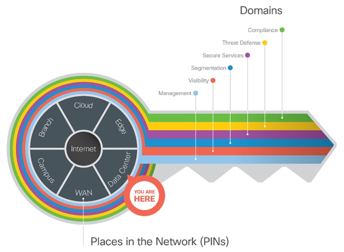
SAFE matches up defensive capabilities against the categories of threats today. SAFE simplifies security by starting with business flows, then addressing their respective threats with corresponding security capabilities, architectures, and designs. SAFE provides guidance that is holistic and understandable.
More information about how Cisco SAFE simplifies security, along with this and other Cisco Validated Designs (CVDs), can be found here.
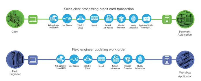
Secure Data Center Business Flows
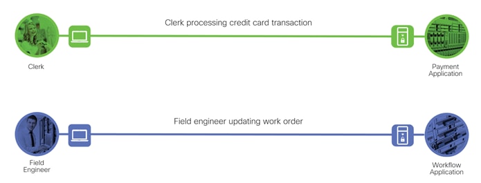
SAFE uses the concept of business flows to simplify the identification of threats and the selection of security capabilities necessary to protect the data flow. The two typical types of data flows in data center are north-south and east-west. North-south refers to data flow that enters or leaves the data center and east-west refers to the data flows within the data center. This solution focus is on the north-south data flow business use cases and the threats they present.
Two examples of north-south data flows are described below:
● In the first example, a clerk located at a branch is processing a credit card transaction on the payment application
● The second example, a field engineer working remotely is updating a work order on the workflow application
Secure Data Center Attack Surface
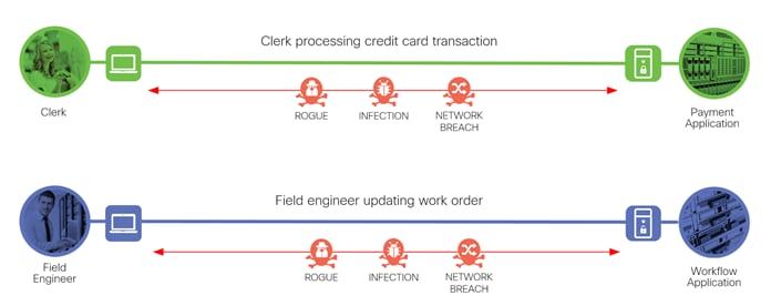
The Secure Data Center solution protects workloads by applying security controls to the attack surface found in the data center. The attack surface in data center spans the business flows used by humans, devices, and the network.
Threats include rogue identity, infections, and advanced persistent threats allowing hackers the ability to take control of your devices and networks. Legacy remote administration access to devices (such as modems) adds additional risk. Zero-day vulnerability attacks can bypass existing controls and infect systems.
The threats represented in the example data flows include:
● Rogue: An unauthorized device on the network
● Infection: A file that has been infected by malware
● Network Breach: Unauthorized access to the network
Cisco’s security approach for the modern cloud applications allows companies to achieve:
● Improved resiliency to enable cloud availability and secure services
● Operational efficiency from automated provisioning, flexibility, and integrated security
● Advanced threat protection from Cisco TALOS – industry-leading threat intelligence to stay up to date, informed, and secure
What is our security approach?
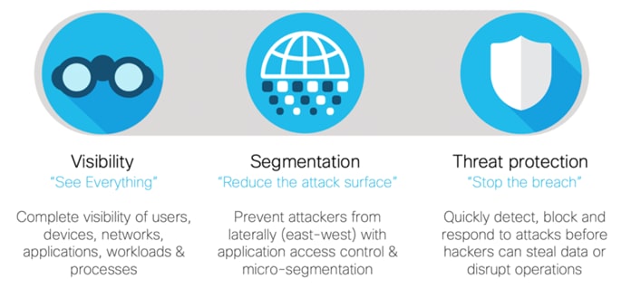
Specific capabilities are necessary to protect the data center and build the appropriate layers of defense. These capabilities work together to create several layers of defense protecting the data center applications. The top priorities or the three pillars that we keep in mind while designing the secure data center solutions are:
● Visibility - Complete visibility of users, devices, networks, applications, workloads, and processes
● Segmentation - Reduce the attack surface by preventing attackers from moving laterally, with consistent security policy enforcement, application access control and micro-segmentation
● Threat Protection - Stop the breach by deploying multi-layered threat sensors strategically in the public cloud to quickly detect, block, and dynamically respond to threats
Specific capabilities are necessary to protect the data center and build the appropriate layers of defense. These capabilities work together to create several layers of defense protecting the data center.
| Icon |
Threat |
Icon |
Capability |
Security Solutions |
| |
Unauthorized access and malformed packets. |
|
Firewall Segmentation |
Cisco Secure Firewall (Firepower Threat Defense (FTD)) Application Security Appliance (ASA)) |
| |
Attacks using worms, viruses, or other techniques. |
|
Intrusion Prevention System (IPS) |
Cisco Secure Firewall (Firepower Threat Defense (FTD)) |
| |
Malware distribution across networks or between servers and devices. |
|
Network Anti-Malware |
Cisco Secure Firewall (Firepower Threat Defense (FTD)) Application Security Appliance (ASA)) |
| |
Attack tools hiding in permitted applications. |
|
Application Visibility Control (AVC) |
Cisco Secure Firewall (Firepower Threat Defense (FTD)) |
| |
Attacks against poorly developed applications and web vulnerabilities. |
|
Web Application Firewall (WAF) |
Cisco Secure Application Delivery Controller (Radware Alteon WAF) |
| |
Theft of unencrypted traffic. |
|
TLS Encryption Offload |
Cisco Secure Application Delivery Controller (Radware Alteon) |
| |
Attackers or malicious users accessing restricted information. |
|
Identity/Authorization |
Cisco Identity Services Engine (ISE) Cisco Secure Access by Duo |
Developing a defense-in-depth architecture requires identifying existing threats and applying appropriate security capabilities to thwart them.
The two business flows defined earlier are shown with the necessary security capabilities.
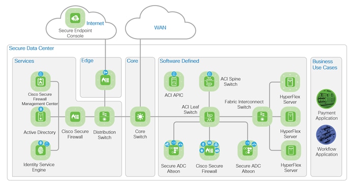
The Cisco Secure Data Center reference architecture is a solution that includes the best of Cisco’s products for a modern data center.
● The data center network is based on Cisco Application Centric Infrastructure (ACI)
● Cisco Secure Firewall (Firepower Threat Defense) protects the data center infrastructure
● Firepower Management Center (FMC) manages Cisco Secure Firewall and integrated services
● Advanced Malware Protection (AMP) for Networks on the Cisco Secure Firewall detects malware
● Secure Application Delivery Controller (Secure ADC) provides TLS offload and Web Application Firewall (WAF)
● Identity Services Engine (ISE) enables 802.1x authentication
Product information and capabilities will be discussed in the Implementation section below.
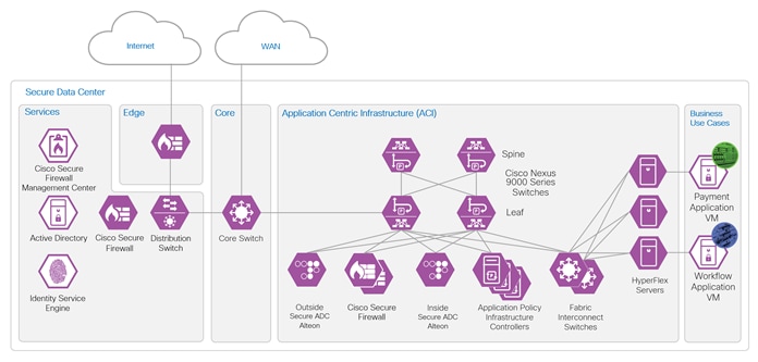
The secure data center architecture is illustrated in the figure below. The figure highlights the services and components discussed in this guide and their place in the network. The Edge connects the data center to Internet and cloud services, like Secure Endpoint Console. It also connects remote users to the data center with VPN services. The WAN connects the branch offices to the data center. The Internet and WAN are places in the network (PINs) that are outside of the data center. Refer to the SAFE Architecture Guides for details on other PINs. Within the data center, the Core connects the Services zone and Software Defined zone.
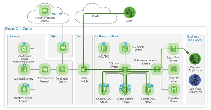
The first business use case depicted below is a payment application for PCI compliance. The clerk is depicted by the green token is connected to the WAN from a branch office. The clerk is processing a sales transaction that includes a credit card and is accessing the payment application in the data center. The data flow enters the data center Core zone from WAN and is routed to the Software Defined zone. Software Defined zone refers to software defined segmentation, which is delivered by Cisco Application Centric Infrastructure (ACI).
The flow enters the ACI Leaf through a Layer 3 Out (L3Out), and an ACI Service Graph allow the flow through to the external Alteon. The Alteon Web Application Firewall inspects and the SSLi (TLS offload) decrypts the flow. The unencrypted flow is redirected by ACI to the Firepower for inspection. If the flow passes all inspections, it is returned to the ACI leaf switch and routed to the internal Alteon. The internal Alteon encrypts the flow and routes it back to ACI. ACI routes the flow to the HyperFlex servers hosting the application. If the flow fails inspection at any point, it is dropped by the inspecting appliance.
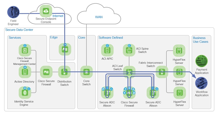
The second business use case depicted secures remote access for employees accessing an application in the data center. The field engineer is depicted by the blue token is accessing the data center using a VPN connection to submit a work order to the workflow application. The data flows from the Internet enters the Edge zone, where the VPN termination is handled by the Edge. The flow is routed to the distribution switch in the Services zone and then to the Core zone. The path from the core to the application is the same as the business use case 1.
The network topology below illustrates the nodes in the Cisco ACI fabric. The fabric consists of two leaf nodes, two spine nodes and three Application Policy Infrastructure Controllers (APICs). Each leaf node connects to the two spine nodes and each APIC controller connects to the two leaf nodes. The leaf nodes do not direct connect to each other nor do the spine nodes. The leaf nodes act as the connection point for all servers, storage, physical or virtual L4-L7 service devices, and external networks. The spine nodes act as the high-speed forwarding engine between leaf nodes. The Cisco ACI fabric is managed, monitored, and administered by the Cisco APICs. Each node on the network, the Cisco ADC, Cisco Secure Firewall and Fabric Interconnect connects to both leaf nodes with port-channel interfaces. A secure overlay management network is implemented for out of fabric accessibility but is not depicted.
The purple design icons represent the product selected to provide the security capabilities required to protect the business use cases. Solid purple icons represent physical appliances, and the icons with the white background represent virtual appliances or software.
The table below lists the hardware models and software versions tested.
| Component |
Model |
Version |
| ACI APICs |
APIC-SERVER-L1 |
apic-5.1(3e) |
| ACI Spine Switches |
N9K-C9504 |
n9000-15.1(3e) |
| ACI Leaf Switches |
N9K-C93180YC-FX |
n9000-15.1(3e) |
| Cisco Secure ADC Alteon |
Alteon D-7612 |
32.6.3.0 |
| Cisco Secure Firewall Management Center |
Firepower Management Center Virtual Appliance VMWare |
7.0.0.1-15 |
| Cisco Secure Firewall |
Firepower 9300 Security Appliance, one SM-36 Module |
7.0.0.1-15 |
Implementation Main Components
Cisco Application Centric Infrastructure (ACI)
Cisco Application Centric Infrastructure (ACI) technology enables the integration of virtual and physical workloads in a programmable, multi-hypervisor fabric to build a multiservice or cloud data center. The Cisco ACI fabric consists of leaf and spine switches that are provisioned as a single entity to provide switching and routing functions. The Cisco ACI fabric consists of discrete components that operate as routers and switches, but it is provisioned and monitored as a single entity.
ACI Endpoint Groups (EPGs) and Contracts
Endpoints are devices that connect to the network directly or indirectly. They can be physical or virtual devices, such as servers, virtual machines, network attached storage, or clients on the internet. Cisco ACI uses Endpoint Groups (EPGs) to group endpoints that have common policy requirements, such as security or Layer 4 to Layer 7 services to simplify the management of security and services.
The fundamental security architecture of the ACI solution follows an allow-list model. A contract is a policy construct used to define communication between EPGs. Without a contract between EPGs, no communication is permitted between the EPGs by default.
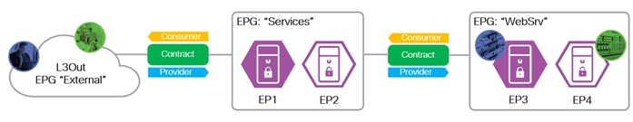
EPGs provides and consumes contracts. In the figure below, the “External” EPG consumes the contract the “Services” EPG provides and the “Services” EPG consumes the contract the “WebSrv” EPG provides. An EPG can provide and consume the same contract.
A contract is not required to allow communication between endpoints in the same EPG. In the figure below, communication between EP1 and EP2 or between EP3 and EP4 is permitted without a contract.
An endpoint can belong to only one EPG. An endpoint can be physical, virtual or a container and can co-exist in the same EPG. Endpoints are assigned to EPGs based on EPG types:
● L3Out EPG - based on the IP subnet (longest prefix match)
● EPG - based on the leaf interface and Virtual LAN (VLAN) ID, or leaf interface and Virtual Extensible LAN (VXLAN)
● uSeg EPG (also called micro-EPG) - based on IP, MAC VM attributes such as VM name, or a combination of IP, MAC, and those attributes
ACI Service Graph
Cisco ACI enables the insertion of Layer 4 through Layer 7 (L4-L7) functions using a concept called a service graph. Using the service graph, Cisco ACI can redirect traffic between security zones to a firewall or a load balancer, without the need for the firewall or the load balancer to be the default gateway for the servers.
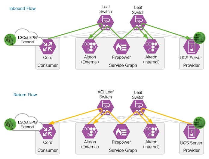
When inserting a load balancer into the network, it is important to understand the traffic flow. In a typical deployment, incoming and return flow must pass through the same load balancer. When a client sends a request to an application behind a load balancer, the client is sending the request to the load balancer VIP (Virtual IP address). The load balancer forwards the request to the server hosting the application with the client IP address as the source. If the server return flow bypasses the load balancer, the client will drop the traffic because the return flow source IP address (the server) is not the same IP address (load balancer VIP) the client sent the request to. The inbound and return flow are illustrated in the figure below.
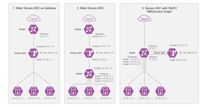
Three design options to insert a load balancer into the network are illustrated below. The load balancer is depicted as the Secure ADC in the diagram.
Design 1 is an inline design with the Secure ADC inside interface configured as the default gateway on the servers. All inbound and return traffic between the clients and servers traverses this path, so no SNAT or PBR required.
Design 2 is like design 1 with a router added between the Secure ADC and servers, making a “L3 Sandwich”. In this design, the router is the gateway for servers and removes the requirement for the Secure ADC to be the gateway for the servers. The servers can reside in different subnets. No SNAT or PBR is required.
Design 3 requires SNAT, PBR or Service Graph with PBR to redirect the return traffic to the Secure ADC. The advantage of this design is the flexibility to bypass the Secure ADC for select types of traffic.
Refer to the Cisco ACI and Cisco Secure ADC Design Guide for more details on load balancer insertion.
Layer 3 Out (L3Out)
The ACI fabric is formed from multiple components such as bridge domains (BDs) and endpoint groups (EPGs) to provide Layer (L2) connectivity or default gateway functions for a group of endpoints within the fabric. Connecting to networks outside of the ACI fabric requires the configuration of a L3Out. The L3Out provides five key functions:
● Learn external routes via routing protocols (BGP, EIGRP, OSPF, and static routes)
● Distribute learned external routes (or static routes) to other leaf switches
● Advertise ACI internal routes (BD subnets) to outside ACI
● Advertise learned external routes to other L3Outs (Transit Routing)
● Allow traffic to arrive from or be sent to external networks via L3Out by using a contract
Cisco Secure Application Delivery Controller (ADC)
In this implementation, the Cisco Secure ADC has been added to provide application load balancing, SSL interception offloading and application security protection with the web application firewall which are integrated in the Cisco Secure ADC.
Cisco Secure ADC is a combination of hardware platforms and software, which deliver a rich set of application delivery capabilities with unmatched performance. It offers a complete set of Layer 4-7 services to ensure the availability, performance, and security of mission-critical applications on-premises and in cloud data centers. These extend to traffic redirection, content modification, persistency, redundancy, advanced health monitoring, and bandwidth management that optimizes the delivery of mission-critical applications. Cisco Secure ADC is designed to dynamically scale when necessary without hardware modifications. It can scale on demand, adding more throughput, services, and virtual ADC (vADC) instances, or by leveraging an external, scalable resource pool (such as server infrastructure) for compute-intensive NG services.
This document covers the SSL Interception inbound and Web Application Firewall capabilities of the Cisco Secure ADC. The additional capabilities listed below are out of scope of this document:
● SSL Interception outbound
● Application Performance Monitoring (APM)
● FastView Web Performance Optimization (WPO)
● Application Re-write
● Application Caching
● Application Protection
● Global Load Balancing
Refer to the Cisco Secure ADC Alteon Data Sheet for more information.
The Cisco Secure Firewall is an industry-leading intelligent security appliance. It provides threat protection, real-time contextual awareness and full stack visibility. The Cisco Secure Firewall is a highly effective and highly reliable next-generation firewall. Threat protection capabilities can be expanded to include Firepower NGIPS, Advanced Malware Protection (AMP) for Networks and URL Filtering.
The Firepower 4100 and 9300 appliances are designed for large campuses, high-performance data centers and service providers. The appliances can create separate logical firewalls for deployment flexibility, quickly inspect encrypted traffic, gain application visibility, detect and block network intrusions, deploy scalable VPNs, and provide integrated protection against DDoS attacks. The Cisco Secure Firewall can cluster devices for scaling performance and provide high availability.
Refer to the Cisco Secure Firewall product portfolio for more information.
The Secure Data Center design implements security controls at different points in network to protect the workload. The Cisco Secure ADC Alteon and the Cisco Secure Firewall (Firepower 9300) appliances are examples of these controls. In this implementation, an Alteon is placed in front of the Firepower 9300 to offload the WAF and SSL decryption (SSL inspection (SSLi)) functions. A second Alteon is placed behind the Firepower 9300 to encrypt the traffic before forwarding to the servers. With the offload of those functions, the Firepower 9300 resources are dedicated to the firewall, AVC, file inspection, IPS and Identity based access control. This “sandwich” configuration provides visibility into encrypted traffic with minimal latency by offloading the SSLi function to purpose-built devices.
The Alteons operate in a two zones configuration, an outside zone and an inside zone. Each zone is a defined as a bridge domain and a subnet in ACI. The Firepower 9300 are configured as a high-availability (HA) pair and operates as a one-arm firewall that connects to a dedicated ACI bridge domain and subnet. The server connects to its own ACI bridge domain and subnet. The figure below illustrates the ACI bridge domains and subnets configuration.
The ACI Service Graph and PBR is the method selected to insert the Alteons and Firepower 9300 appliances into the network path. This method eliminates the need for additional routing and bridging configuration in the ACI fabric. It also eliminates the need for SNAT configuration on the Alteon appliance for the return flow.
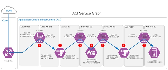
Traffic Flow through the Sandwich.
1 - The WAN data flow enters the ACI fabric through the L3Out Main from the Core. The flow is routed to the ALT-EXT outside interface.
2 - The ALT-Ext inspects (WAF policies) and decrypts (TLS-Offload) the inbound flow. The unencrypted flow is sent to the Alt-Ext BD gateway.
3 - The ACI fabric redirects the flow to the Firepower.
4 - The Firepower inspects the flow and routes it back to the ACI fabric.
5 - The ACI fabric routes the traffic to the internal Alteon outside interface.
6 - The internal Alteon encrypts the flow and routes it to ACI fabric.
7 - The ACI fabric routes the flow to the servers.
This section summaries the configuration of a tenant, the L3Outs, PBRs and the Service Graph.
Prerequisites: An ACI environment with basic configuration, dynamic routing enabled, and network ports configured. Refer to the SAFE Design Guide: Secure Data Center Cisco ACI Multi-Site Reference Design for detailed steps to configure the Cisco ACI environment.
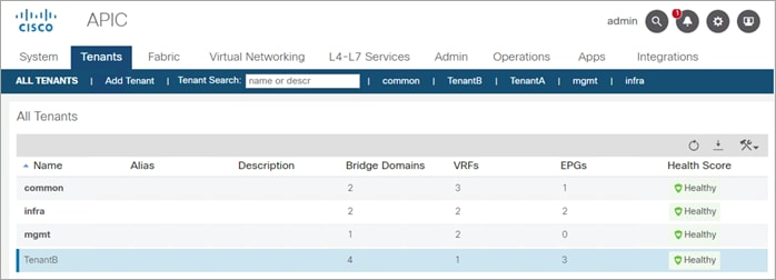
Step 1. Add a tenant named TenantB and create a VRF named VRF-B. The remaining options are left as default.
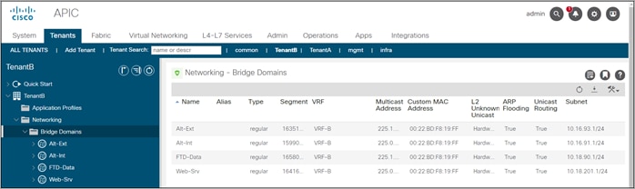
Step 2. Create the following bridge domains in VRF-B; Alt-Ext, Alt-Int, FTD-Data and Web-Srv. Under the L3 Configurations of each domain, config the gateway to route traffic between the bridge domains. L3Out Association is not required for the bridge domains because traffic remain within the ACI fabric.
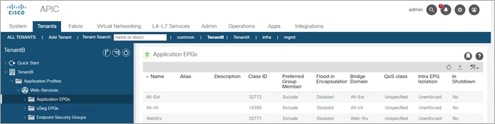
Step 3. Create an Application Profile named Web-Services. Under the Web-Services Application profile, create the Application EPGs Alt-Ext, Alt-Int and Web-Srv and associate each to the corresponding bridge domain. The FTD does not required an EPG because traffic is redirected to it using a PBR.
Step 4. The ACI switch is the Area Border Router (ABR) connecting the Open Shortest Path First (OSPF) Area 0 and Area 1. The ACI switch peers with the Core switch and with the Alteons, Alt-Ext and Alt-Int.
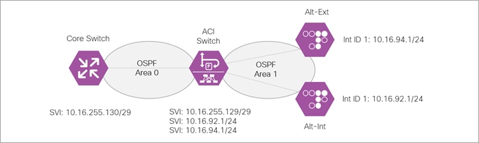
Create two L3Outs, one named L3Out-Main to peer with the Core switch and one named L3Out-Alteon to peer with the two ADC Alteons. The L3Out-Alteon is configured with two interfaces, on to peer with ADC Alt-Ext and other to peer with the ADC Alt-Int.
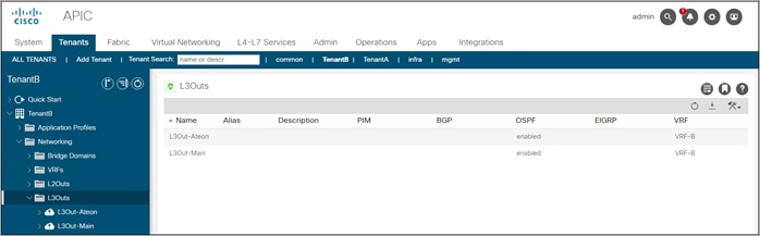
L3Out-Main summary:
● VRF: Tenant-B
● OSPF Area ID: 0
● OSPF Area type: Regular Area
● Interface Type: SVI
● VLAN 1199
● External EPG: ExternalNet
L3Out-Alteon summary:
● VRF: Tenant-B
● OSPF Area ID: 1
● OSPF Area type: Stub Area
● Interface Type: SVI – This interface connects to the Alt-Ext
● VLAN 1194
● Interface Type: SVI – This interface connects to the Alt-Int
● VLAN 1192
● External EPG:
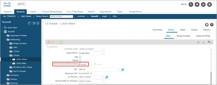
Step 5. Enable Route Control Enforcement Import on both L3Outs (error when enable only on one router)
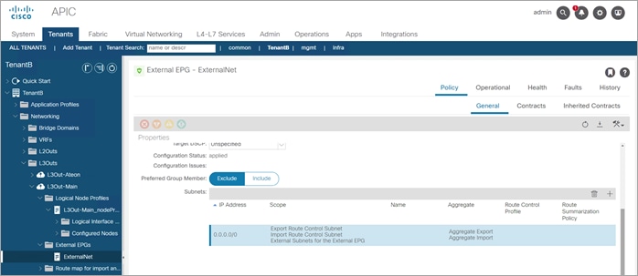
Step 6. Enable Import Route Control on all ext EPGs and export on L3Out-Main
Step 7. Configure L3Out-Main to import routes and export the ALT-Ext VIP route. Configure the L3out-Alteon to import the VIP route from each Alteon.
● L3Out-Main: Import route 0.0.0.0/0 (Extranet)
● L3Out-ALT-Ext: Import route10.22.91.11/32 (Alt-Ext) and delete route 0.0.0.0/0
● L3Out-Alt-Int: Import route 10.22.92.11/32 (Alt-Int) and delete route 0.0.0.0/0
Step 8. Create PBR for Alt-Ext, Alt-Int and FTD-Cluster - IP and MAC
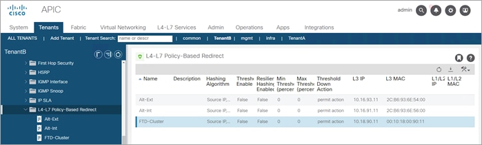
The Outside Alteon:
● Name: Alt-Ext
● MAC: 2C:B6:93:6E:54:00
● IP: 10.16.93.11
The Inside Alteon:
● Name: Alt-Int
● MAC: 2C:B6:93:6E:56:00
● IP: 10.16.91.11
The FTD Cluster:
● Name: FTD-Cluster
● MAC: 00:10:18:00:90:11
● IP: 10.18.90.11
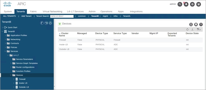
Step 9. Create Device Firewall (FTD), Outside_LB (Alt-Ext) and Inside-LB (Alt-Int).
Note: The configuration of the ACI ports connected to these devices is not covered in this guide.
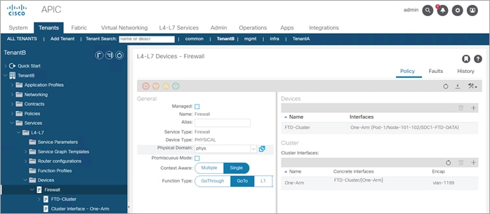
Device Firewall Configuration
General
● Managed: No (uncheck box)
● Name: Firewall
● Service Type: Firewall
● Device Type: Physical
● Physical Domain: phys (select the domain specific to your environment)
● Context Aware: Single
● Function Type: Goto
Devices section:
● Name: FTD-Cluster
● Interfaces:
· Name: One-Arm
· Path: Select the ACI Leaf port(s) connected to the firewall
Cluster Interfaces section:
● Name: One-Arm
● Concrete Interfaces: FTD-Cluster/[One-Arm]
● Encap: vlan-1199 (enter the vlan specific to your environment)
Device Outside Alteon Configuration
General
● Managed: No (uncheck box)
● Name: Outside-LB
● Service Type: ADC
● Device Type: Physical
● Physical Domain: phys (select the domain specific to your environment)
● Context Aware: Single
● Function Type: Goto
Devices section:
● Name: Alt-Ext
● Interfaces:
· Name: Outside
· Path: Select the ACI Leaf port(s) connected to the Alteon outside interface
· Name: Inside
· Path: Select the ACI Leaf port(s) connected to the Alteon inside interface
Cluster Interfaces section:
● Name: Outside
● Concrete Interfaces: Alt-Ext/[Outside]
● Encap: vlan-1194 (enter the vlan specific to your environment)
● Name: Inside
● Concrete Interfaces: Alt-Int/[Inside]
● Encap: vlan-1193 (enter the vlan specific to your environment)

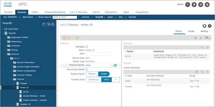
Device Inside Alteon Configuration
General
● Managed: No (uncheck box)
● Name: Inside-LB
● Service Type: ADC
● Device Type: Physical
● Physical Domain: phys (select the domain specific to your environment)
● Context Aware: Single
● Function Type: Goto
Devices section:
● Name: Alt-Int
● Interfaces:
· Name: Outside
· Path: Select the ACI Leaf port(s) connected to the Alteon outside interface
· Name: Inside
· Path: Select the ACI Leaf port(s) connected to the Alteon inside interface
Cluster Interfaces section:
● Name: Outside
● Concrete Interfaces: Alt-Ext/[Outside]
● Encap: vlan-1192 (enter the vlan specific to your environment)
● Name: Inside
● Concrete Interfaces: Alt-Int/[Inside]
● Encap: vlan-1191 (enter the vlan specific to your environment)
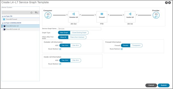
Step 10. Create a new Service Graph Template
● Service Graph Name: Services
● Graph Type: New Graph
● Filter After First Node: Allow All – This is for testing only not recommended for production
● Drag the available device from the left pane to the right pane to build the service graph. Start with Alt-Ext, closest to the consumer, follow by the FTDs and Alt-Int
● The Alteons are configured as two-arm devices
● The FTDs are in routed mode
● Enable Route Redirect on all devices
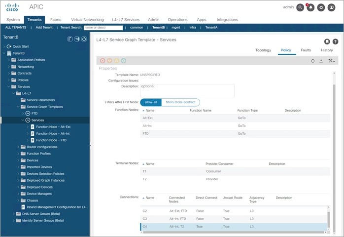
Step 11. Edit the service graph policy to permit the health check from the Alt-Int to servers – change C4 Direct Connect to “True”
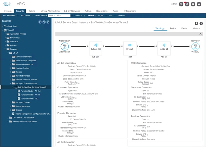
Step 12. Deployed Service Graph “Services”
Consumer: L3Out-Main ext EPG: ExternalNet
Provider: BD WebSrv
Contract: Ext-to-WebSrv;
Alt-Ext Information:
Contract: TenantB/Ext-To-WebSrv
Graph: TenantB/Services
Node: Alt-Ext
Device Cluster: Outside-LB
Load Balancer: two-arm
Policy-Based Redirect: true
Consumer Connector
Type: l3out
L3 Ext Network: TenantB/L3Out-Ateon/Alt-Ext
L3 Destination
(VIP): true
Service EPG
Policy: /
Cluster Interface: Outside
Provider Connector
Type: bd
BD: TenantB/Alt-Ext
L3 Destination
(VIP): true
Redirect Policy: svcCont/Alt-Ext
Service EPG
Policy: /
Cluster Interface: Inside
FTD Information:
Contract: TenantB/Ext-To-WebSrv
Graph: TenantB/Services
Node: FTD Device
Cluster: Firewall
Firewall: routed
Policy-Based Redirect: true
Consumer Connector Type: bd
BD: TenantB/FTD-Data
L3 Destination (VIP): true
Redirect Policy: svcCont/FTD-Cluster
Service EPG Policy: /
Cluster Interface: One-Arm
Provider Connector Type: bd
BD: TenantB/FTD-Data
L3 Destination (VIP): true
Redirect Policy: svcCont/FTD-Cluster
Service EPG Policy: /
Cluster Interface: One-Arm
Alt-Int Information:
Contract: TenantB/Ext-To-WebSrv
Graph: TenantB/Services
Node: Alt-Int
Device Cluster: Inside-LB Load
Balancer: two-arm
Policy-Based Redirect: true
Consumer Connector Type: l3out
L3 Ext Network: TenantB/L3Out-Ateon/Alt-Int L3
Destination (VIP): true
Service EPG Policy: /
Cluster Interface: Outside
Provider Connector
Type: bd
BD: TenantB/Alt-Int
L3 Destination (VIP): true
Redirect Policy: svcCont/Alt-Int
Service EPG Policy: /
Cluster Interface: Inside
External Alteon Configuration
This section covers the following configurations:
● Configure data interfaces
● Create VIP
● Define Server group and health check
● Generate and assign a Self-signed certificate
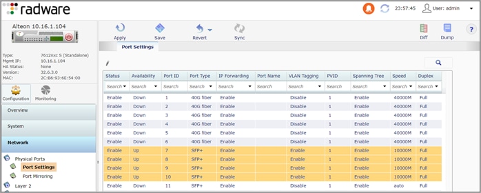
This section covers the configuration of the ALT-Ext Alteon. The ports configuration is illustrated below.

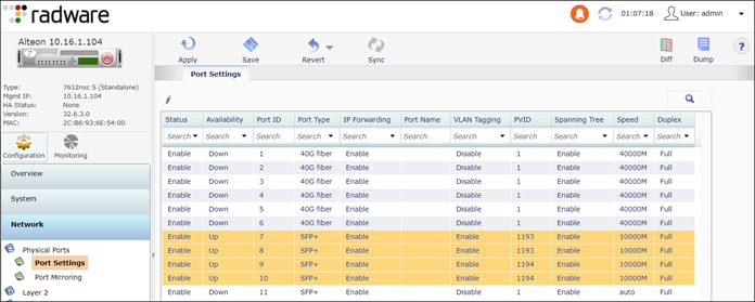
Step 1. Enable interface 7 through 10.
Navigate to Configuration > Network > Physical Ports > Port Settings
● Enable Port: Enable
● Port Settings > VLAN Tagging: Enable
● PVID: Leave as default of 1. When the VLANs are created in step 3, update the ports with the new PVIDs
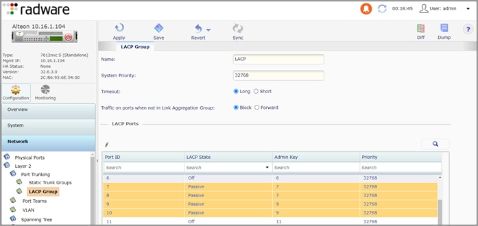
Step 2. Create a Link Aggregation Control Protocol (LACP) Group.
The Alteon uses Admin Key to define Link Aggregation Groups (LAG). This step creates two LAGs, the inside LAG with member ports 7 and 8 and the outside LAG with member ports 9 and 10.
Navigate to Configuration > Network > Layer 2 > Port Trunking > LACP Group
● LACP Group:Name: LACP
● LACP Ports: 7 and 8 (inside)
◦ LACP State: Passive
◦ Admin Key: 7
● LACP Ports: 9 and 10 (outside)
◦ LACP State: Passive
◦ Admin Key: 9
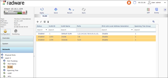
Step 3. Create two VLANs, one for the inside interface and one for the outside interface.
Navigate to Configuration > Network > Layer 2 > VLAN
Inside VLAN
● Enable VLAN
● VLAN ID: 1193
● VLAN Name: Inside
● VLAN Settings: Selected: Port 7 and 8
Outside VLAN
● Enable VLAN
● VLAN ID: 1194
● VLAN Name: Outside
● VLAN Settings: Selected: Port 9 and 10
Step 4. Assign ports to the new PVIDs.
Navigate to Configuration > Network > Physical Ports > Port Settings
● Assign ports 7 and 8 to PVID 1193
● Assign ports 9 and 10 to PVID 1194
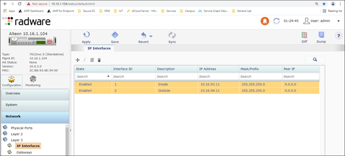
Step 5. Configure interface IP addresses. Network > Layer 3 > IP Interfaces
● Inside Interface
◦ Interface ID: 1
◦ Description: Inside
◦ IP Address: 10.16.93.11
◦ Mask: 255.255.255.0
◦ VLAN: 1193
● Outside Interface
◦ Interface ID: 2
◦ Description: Outside
◦ IP Address: 10.16.94.11
◦ Mask: 255.255.255.0
◦ VLAN: 1194
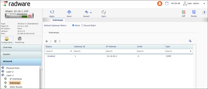
Step 6. Configure the appliance default gateway.
Navigate to Configuration > Network > Layer 3 > Gateways
● Enable Gateway
● Gateway ID: 1
● IP address: 10.16.94.1
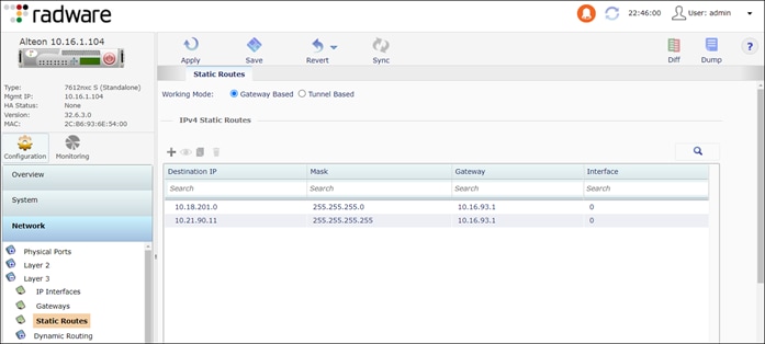
Step 7. Add static routes to the internal Alteon (ALT-Int) VIP 10.21.90.11/32.
Navigate to Configuration > Network > Layer 3 > Static Routes
● To ALT-Int VIP
◦ Destination IP: 10.22.90.11
◦ Mask: 255.255.255.255
◦ Gateway: 10.16.93.1
● To servers
◦ Destination IP: 10.18.201.0
◦ Mask: 255.255.255.0
◦ Gateway: 10.16.93.1
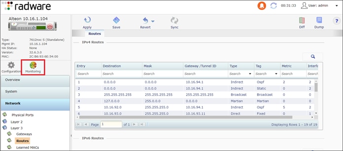
Step 8. The Alteon outside physical interface (10.16.94.11) and VIP (10.22.92.11) are on different subnets. For traffic to reach the Alteon VIP, a route is required on ACI. OSPF is used in this implementation and enables the Alteon to peer with ACI to advertise the VIP route.
Navigate to Configuration > Network > Layer 3 >Dynamic Routing
Dynamic Routing:
● Router ID: 10.16.94.11
OSPF:
● Enable OSPF
● Areas:
◦ Enable Area
◦ Area Number: 2
◦ Area ID: 0.0.0.1
◦ Area Type: Stub
● Interfaces:
◦ Enable Interface
◦ Interface ID: 2
◦ Area Number: 1
● Host:
◦ Enable Host
◦ Host ID: 1
◦ IP Address: 10.22.92.11 This is the VIP address to advertise in OSPF.
◦ Area Number: 1
Switch to Monitoring to view the route table and check for OSPF routes.
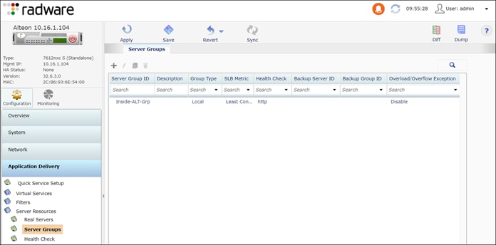
Step 9. Configure server group to monitor. The health check is monitoring the inside Alteon VIPs with a HTTP request.
Navigate to Application Delivery > Server Resources> Server Groups
Real Servers:
● Enable Real Server: Enabled
● Real Server ID: ALT-Int-VIP1
● Server IP Address: 10.22.91.11
Server Groups:
● Server Group ID: Inside-Alteon-Grp
● Real Servers:
◦ Add the ALT-Int-VIP1 from Available to Selected
● Group Settings:
◦ Health Check: HTTP
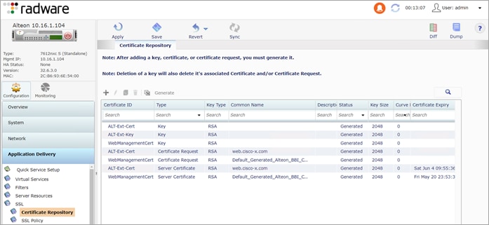
Step 10. Create a private (self-signed) certificate. This certificate is used to establish a secure connection between the endpoint and the outside Alteon. In a production environment, using a public certificate is recommended.
Navigate to Application Delivery > SSL
● Enable SSL
● Certificate Repository:
◦ Add (+) a Certificate
◦ Certificate ID: ALT-Ext-Cert
◦ Type: Server Certificate
◦ Settings:
◦ Common Name: <server.domain.com>
◦ Add (+) a Key
◦ Certificate ID: ALT-Ext-Key
◦ Type: Key
The steps to configure the internal Alteon is similar to the external Alteon with the following exceptions:
● IP addresses and VLANs are IP addresses
● Monitor the web servers
● No self-signed SSL certification is required
Step 1. Enable network interface 7 through 10.
Navigate to Configuration > Network > Physical Ports > Port Settings
● Enable Port: Enable
● Port Settings > VLAN Tagging: Enable
● PVID: Leave as default of 1. When the VLANs are created in step 3, update the ports with the new PVIDs.
Step 2. Create a Link Aggregation Control Protocol (LACP) Group.
Navigate to Network > Layer 2 > Port Trunking > LACP Group
The Alteon uses Admin Key to define Link Aggregation Groups (LAG). This step creates two LAGs, the inside LAG with member ports 7 and 8 and the outside LAG with member ports 9 and 10.
● LACP Group:Name: LACP
● LACP Ports: 7 and 8 (inside)
◦ LACP State: Passive
◦ Admin Key: 7
● LACP Ports: 9 and 10 (outside)
◦ LACP State: Passive
◦ Admin Key: 9
Step 3. Create two VLANs, one for the inside interface and one for the outside interface.
Navigate to Network > Layer 2 > VLAN
Inside VLAN
● Enable VLAN
● VLAN ID: 1191
● VLAN Name: Inside
● VLAN Settings: Selected: Port 7 and 8
Outside VLAN
● Enable VLAN
● VLAN ID: 1192
● VLAN Name: Outside
● VLAN Settings: Selected: Port 9 and 10
Step 4. Assign ports to the new PVIDs.
Navigate to Network > Physical Ports > Port Settings
● Assign ports 7 and 8 to PVID 1191
● Assign ports 9 and 10 to PVID 1192
Step 5. Configure interface IP addresses.
Navigate to Network > Layer 3 > IP Interfaces
Inside Interface
● Interface ID: 1
● Description: Inside
● IP Address: 10.16.91.11
● Mask: 255.255.255.0
● VLAN: 1191
Outside Interface
● Interface ID: 2
● Description: Outside
● IP Address: 10.16.92.11
● Mask: 255.255.255.0
● VLAN: 1192
Step 6. Configure the appliance default gateway.
Navigate to Configuration > Network > Layer 3 > Gateways
● Enable Gateway
● Gateway ID: 1
● IP address: 10.16.92.1
Step 7. Add static routes to the servers (10.18.201.0/24).
Navigate to Network > Layer 3 > Static Routes
Routes to application servers
● Destination IP: 10.18.201.0
● Mask: 255.255.255.0
● Gateway: 10.16.91.1
Step 8. Dynamic routing is required because the VIP and the outside interface are on diffident subnets. The dynamic routing enables the Alteon to advertise the VIP to the ACI and the WAN. The dynamic routing protocol selected for this implementation is OSPF.
Navigate to Configuration > Network > Layer 3 >Dynamic Routing
Dynamic Routing:
● Router ID: 10.16.92.11
OSPF:
● Enable OSPF
● Areas:
◦ Enable Area
◦ Area Number: 2
◦ Area ID: 0.0.0.1
◦ Area Type: Stub
● Interfaces:
◦ Enable Interface
◦ Interface ID: 2
◦ Area Number: 1
● Host:
◦ Enable Host
◦ Host ID: 1
◦ IP Address: 10.22.91.11 This is the VIP address to advertise in OSPF.
◦ Area Number: 1
Switch to Monitoring to view the route table and verify OSPF routes.
Step 9. Configure server group to monitor. The health check is monitoring the inside Alteon VIPs with a HTTP request.
Navigate to Configuration > Application Delivery > Server Resources>
Real Servers:
● Enable Real Server: Enabled
● Real Server ID: ALT-Int-VIP1
● Server IP Address: 10.22.91.11
Server Groups:
● Server Group ID: WebSrv
● Real Servers:
◦ Add the ALT-Int-VIP1 from Available to Selected
● Group Settings:
◦ Health Check: HTTP
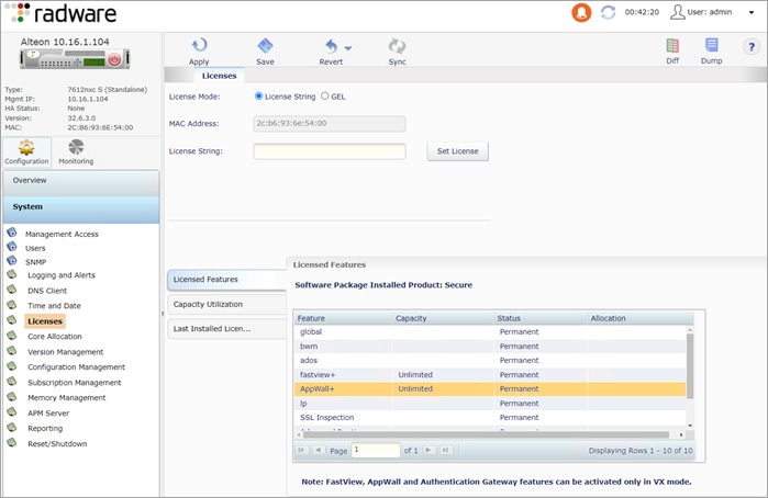
Alteon AppWall+ (WAF) Configuration:
Verify that the Alteon appliance is licensed for the AppWall+ feature.
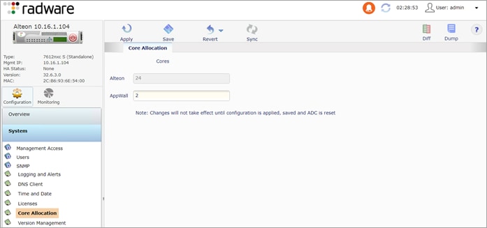
Step 10. Allocate CPU resources to AppWall+
Navigate to Configuration > System > Core Allocation. On the Core Allocation tab, enter 2 for AppWall. Click Submit, Apply and Save.
A message displayed “The change will take effect after the next reboot.”
Reboot the system by navigating to System > Reset/Shutdown > Reset and Confirm Reset.
Step 11. Enable the AppWall+ Service
Navigate to Configuration > Security > Web Security. On the Web Security tab, select Enable AppWall.
Click Submit, Apply and Save.
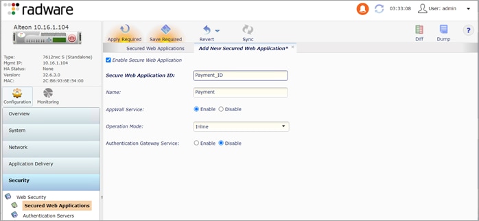
Step 12. Create a Secured Web Application ID
Navigate to Configuration > Security Web > Secured Web Application. Click the + sign. On the Add New Secured Web Application tab, enter the following:
● Enable Secure Web Application: check
● Secure Web Application ID: Payment_ID
● Name: Payment
● AppWall service: Enable
● Operation Mode: Inline
● Click Submit, Apply and Save.
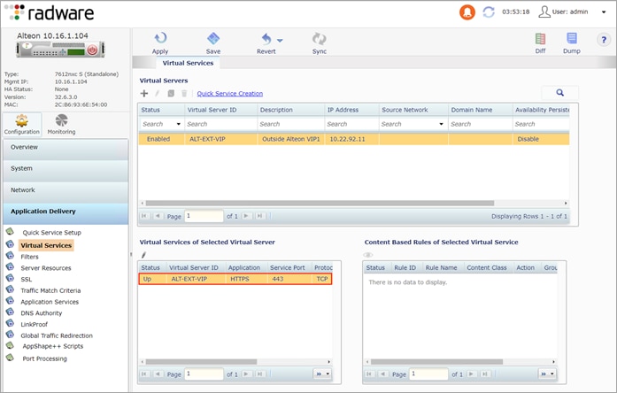
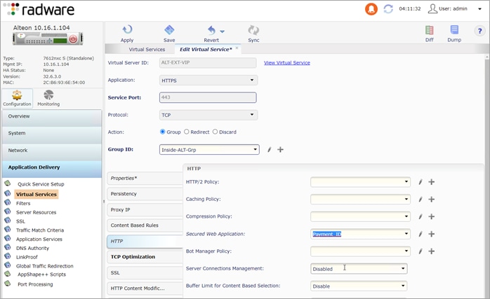
Step 13. Assign Secure Application ID to VIP
Navigate to Configuration > Application Delivery > Virtual Services. Under Virtual Services of Selected Virtual Server, select the virtual service. Click the pencil to edit the virtual service. Click the HTTP tab and select Payment_ID for Secure Web Application. Click Submit, Apply and Save.
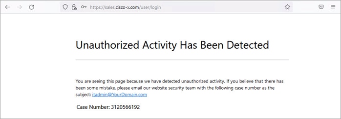
Step 14. Create an Internal Security Page (Blocked Message)
The internal security page is displayed when unauthorized activity is detected, and the request is blocked. The page message is customizable and includes a case number for further investigation.
1 - Create a folder named SecurityPages and two files named InternalSecurityPage.html and ExternalSecurityPage.asp (not required for the test cases in this implementation). Use a text editor to add the content from Appendix D to each file.
2 - Create a zip of the folder SecurityPages.
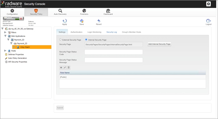
3 - Login to the Radware Security Console https://<ADC-Mgmt-IP>/appwall-webui/ (ex. https://10.16.1.104/appwall-webui/) and navigate to Security Policy > <node name> Gateway > Web Applications > <web applications name> > <tunnel name> > <host>.
4 - In the Settings tab, select the Internal Security Page button and click Add Internal Security Page.
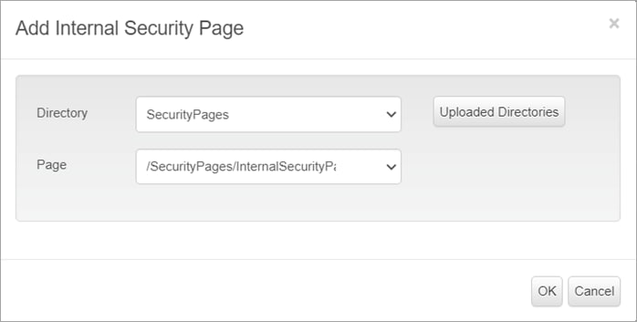
Step 15. In the pop-up window, click the Upload Directories and select the zip file created in step 2. From the drop-down menu, select the Directory and Page and click OK.
Step 16. Click Submit, Apply and Save.
Cisco Firepower Management Center (FMC) and Firepower 9300 Configuration
This section summarizes the configuration of the FMC Access Control, Application Visibility and Control, IPS, and File Inspection policies.
Prerequisites:
● A configured installation of FMC with Directory Services integration
● FTDs configured in cluster mode and registered with FMC
Summary of steps:
● Define the network object Payment Application Servers -> ALT-Int-VIP
● Create the Intrusion policy
● Create File Inspection policy
● Select groups AD integration
● Create access control and apply the IPS policy, File Inspection policy, User Identity, Application filter and network objects
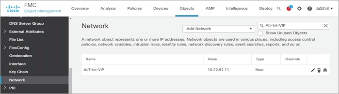
Step 1. Create a network object for the VIP
Navigate to Objects > Object Management a click Add Network > Add Object. Enter the information below and click Save.
● Name: ALT-Int-VIP
● Network: Host
● 10.22.91.11
Step 2. To create an Intrusion Policy, click Policies > Intrusion and Create Policy. In the Create Intrusion Policy popup window, enter the information below and click Save.
● Name: SDC_Intrusion_Policy
● Inspection Mode: Prevention
● Base Policy: Balanced Security and Connectivity
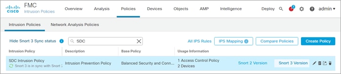
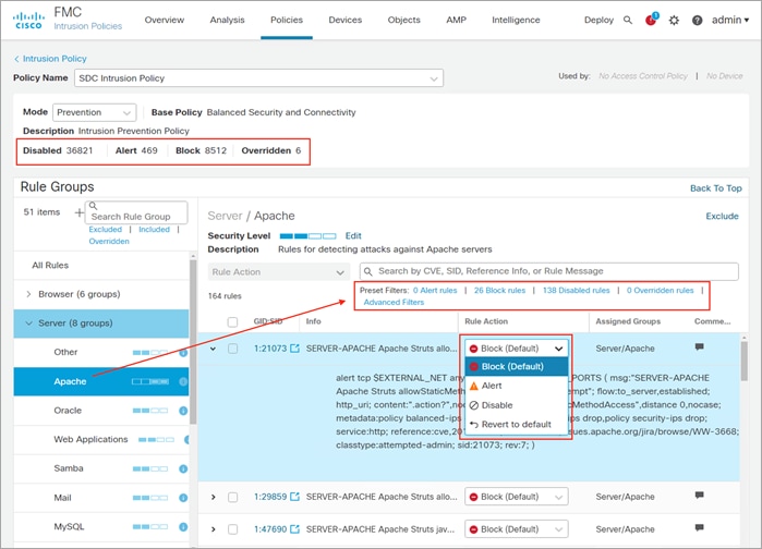
To view or edit the policy, click Snort 2 Version. The policy screen displays the number of rules set to Disabled, Alert, Block and Overridden in the policy.
It also provides the ability to search rules by CVE, SID, Reference Info or Rule Message and edit the action for that rule. Details of the threat can be viewed by expanding the rule. For more details on Intrusion Policy and Snort 2, please refer appendix C.
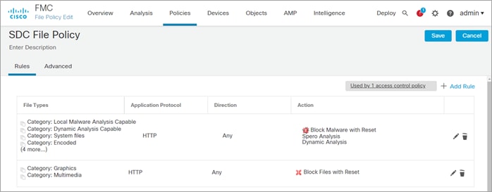
Step 3. Create File policy
Navigate to Policies > Malware and File. Click New File Policy and enter the name SDC File Policy and click Save.
● On the Rules tab, click Add Rule
◦ Direction: Any
◦ Check Spero Analysis for MSEXE and Dynamic Analysis
◦ File Type Categories: Select all but exclude Multimedia
◦ Click Add and Save
● Add another rule to Multimedia, click Add Rule
◦ Application Protocol: HTTP
◦ Direction: Any
◦ Action: Block Malware
◦ Check Spero Analysis for MSEXE and Dynamic Analysis
◦ File Type Categories: Select Multimedia
◦ Click Add and Save
Step 4. Identity Policy
Prerequisite: A configured realm
● Navigate to Policies > Identity and click New Policy. In the pop-up window, enter the name SDC Identity Policy and Click Save
● Click the pencil to edit the SDC Identity Policy
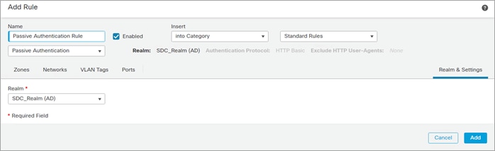
● Click Add Rule and enter the following:
◦ Name: Passive Authentication Rule
◦ Click Realm and Settings and select the preconfigured realm. Click Add.
Step 5. Create an Access Rule
Navigate to Policies > Access Control and click New Policy.
In the pop-up window, enter the following:
● Name: SDC FTD Cluster
● Default Action: Block all traffic
● Target Devices: SDC-FTD-C1 and click Add to Policy
● Click Save
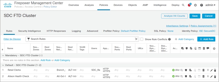
Click the pencil to edit the SDC FTD Cluster policy. In the pop-up window, enter the following:
● Name: Retail Clerk
● Action: Allow
● Select the Networks tab:
◦ Networks: Select Branch_Networks and click Add to Source Networks
◦ Networks: Select ALT-Int-VIP and click Add to Destination.
● Select the Users tab:
◦ Available Realms: Select the SDC_Realm
◦ Available User: Select the Sales and click Add to Rule
● Select the Applications tab
◦ Available Applications: Select HTTP and HTTPS and click Add to Rule
◦ Available User: Select the Sales and Add to Rule
● Select the Inspection tab
◦ Intrusion Policy: SDC Intrusion Policy
◦ File Policy: SDC File Policy
● Select the Logging tab and check the following:
◦ Log at the Beginning of Connection
◦ Send Connection Events to Firepower Management Center
● Click Save
Repeat the previous steps to create a rule to permit the health check between the Alt-Ext and the Alt-Int
● Name: LB Health Check
● Networks:
◦ Source: Alt-Ext-Inside_Int
◦ Destination: Alt-Int-VIP
● Application: HTTP and HTTPS
● Logging: Check the following boxes
◦ Log at the Beginning of Connection
◦ Send Connection Events to Firepower Management Center
● Click Save
Step 6. Navigate to Deploy > Deployment. Select the SDC-FTD-C1 and click Deploy
Test Case 1 – Identity Access Control
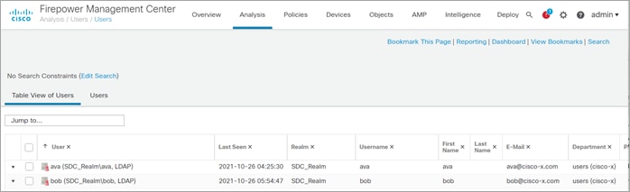
Network users are visible in FMC through the realm integration with AD. In the following use cases, Ava is the clerk and Bob is the field engineer.
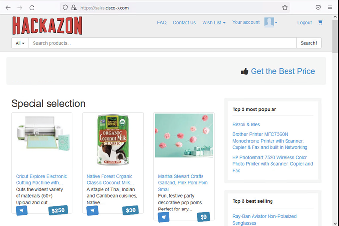
In this use case, the Hackazon site represents the sales order payment application. The policy in FMC allows members of the Sales group access to the sales site. The clerk is a member of the Sales group in AD and is allowed access to site.
The field engineer is not a member of the Sales group and is blocked by the Default Action Access Control of Block all traffic.
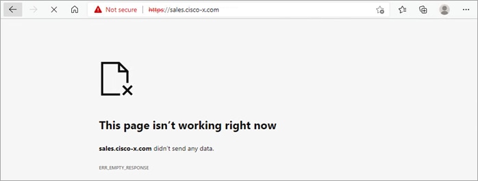
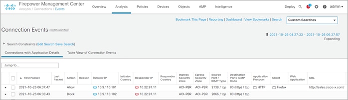
The FMC Connect Events log shows the clerk (Ava/10.9.110.101) was allowed to connect to the server and the field engineer (Bob/10.9.110.102) was blocked.
The clerk attempts to upload a bitmap image which not permitted by policy.
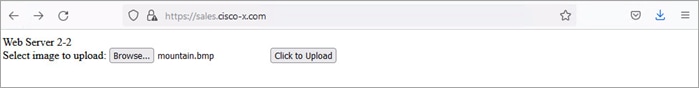

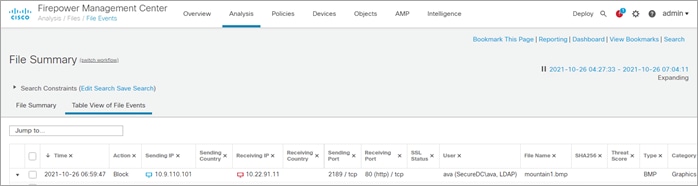
The FMC File Summary log shows the clerk (Ava/10.9.110.101) file upload was blocked by the Secure Firewall.
Test Case 3 - Intrusion Prevention
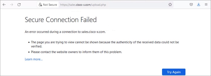
The clerk attempts to upload a text file named Mal-Test.txt.
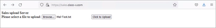
The upload was blocked.
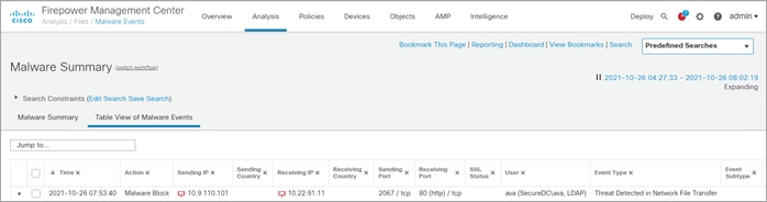
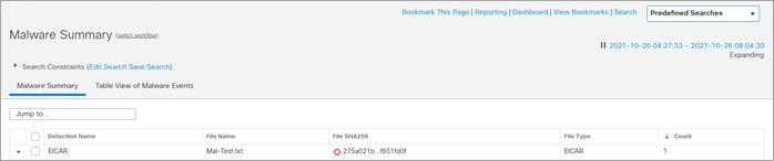
The FMC Malware Summary log shows the file upload was blocked due to malware detected.
The threat detected is EICAR in the Mal-Test.txt.
Test Case 4 – Web Application Firewall
In this test case, a simple SQL injection is used to demonstrate the ADC WAF capability. The string ‘ OR 1=1 is entered as the username in an attempt to retrieve the complete list users from system.
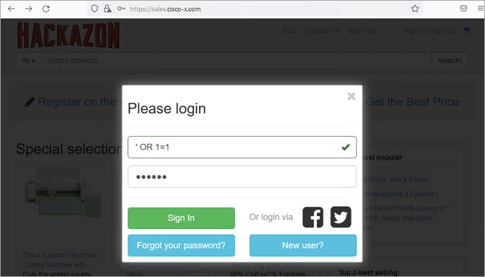
The SQL injection attempt is detected and blocked by the Secure ADC. A case number is provided for further investigation.
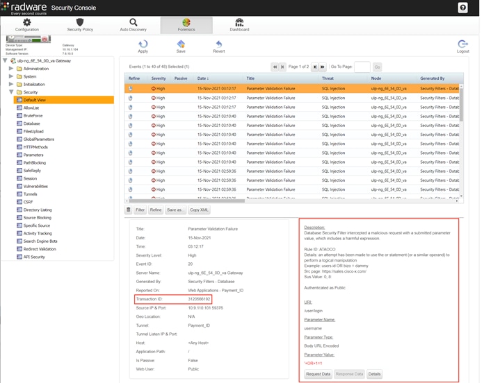
To review the case number, open a web browser and go to https://<SDC Management IP>/appwall-webui/. Navigate to Forensics > <node_va> Gateway > Security > Default View. Use the filter to search for the case number. Select the case in the right pane to view the case details such as which rule blocked the connection, the URI, parameter and parameter value.
The following product licenses were used for the solution validation testing.
Alteon - Global, IP, SSL Inspection, AppWall+
APIC - Smart License: ACI_LEAF_BASE_10G
FMC – Smart License: FMCv, Base, Malware, Threat, URL Filtering, Secure Endpoint account
| Acronym |
Definition |
| ACL |
Access Control List |
| ADC |
Application Delivery Controller |
| AMP |
Advanced Malware Protection |
| AMP4E |
Advanced Malware Protection for Endpoints |
| ACI |
ACI – Application Centric Infrastructure |
| APIC |
Application Policy Infrastructure Controller |
| BD |
Bridge Domain |
| EP |
Endpoint |
| EPG |
Endpoint Group |
| FDM |
Firepower Device Manager |
| FMC |
Firepower Management Center |
| FTD |
Firepower Threat Defense |
| LACP |
Link Aggregation Control Protocol |
| NGIPS |
Next Generation Intrusion Prevention System |
| OSPF |
Open Shortest Path First |
| PBR |
Police Based Routing |
| PIN |
Place in network |
| SNAT |
Source Network Address Translation |
| TLS |
Transport Layer Security |
| VIP |
Virtual IP |
Cisco SAFE
Cisco SAFE Main Site. Includes Overview, Architecture and Design Guides, Related Resources, and Toolkits
Cisco ACI
Cisco APIC product page. Includes Release Notes, Configuration Guides, Technotes, Installation and Upgrade guides.
Cisco Application Centric Infrastructure Policy-Based Redirect Service Graph Design White Paper
Service Graph Design with Cisco ACI (Updated to Cisco APIC Release 5.2) White Paper
Cisco Secure ADC
Cisco Secure ADC: Alteon® Application Delivery Controller (ADC) Data Sheet
Cisco ACI and Cisco Secure ADC Design Guide
Cisco Secure Firewall
Cisco Firepower 9300 product page
Cisco Firepower Management Center documentations
Firepower Management Center
FMC Configuration Guide: Section File Polices and Advance Malware Protection
Appendix D – ADC Security Pages (Blocked Message)
Note: Replace your@email.address with your notification email address when you create these files below.
The following is the content of the InternalSecurityPage.html file.
<HTML>
<HEAD>
<TITLE>Unauthorized Request Blocked</TITLE>
<META HTTP-EQUIV="Content-Type" Content="text/html; charset=UTF-8">
<meta http-equiv="Cache-Control" content="no-cache, no-store, must-revalidate" />
<meta http-equiv="Pragma" content="no-cache" />
<meta http-equiv="Expires" content="0" />
</HEAD>
<BODY>
<BR>
<TABLE align=center cellpadding="0" cellspacing="0" border="0">
<TR>
</TR>
</TABLE>
<BR>
<TABLE width="700" align=center cellpadding="0" cellspacing="0" border="0">
<TR>
<TD width="60" align="left" valign="top" rowspan="3"></TD>
<TD id="mainTitleAlign" valign="middle" align="left" width="*">
<H1>Unauthorized Activity Has Been Detected</H1>
</TD>
</TR>
<TR><TD> </TD></TR>
<TR><TD><DIV class="divider"></DIV><BR><BR></TD></TR>
<TR><TD></TD>
<TD>
<H3>You are seeing this page because we have detected unauthorized activity. If you think this was an error, please email our website security team with the following case number as the subject:
<script language="javascript"> if (window._event_transid !== undefined) document.write('<a href="mailto:your@email.address?Subject=Security Page - Case Number ' + window._event_transid + '&body=Case Description:">your@email.address</a>');else document.write('<a href="mailto:your@email.address?Subject=Security Page - Case Number N/A&body=Case Description:">your@email.address</a>'); </script>
<P>
<table border="0">
<tr>
<td>Case Number:</td>
<td><script language="javascript">if (window._event_transid !== undefined) document.write(window._event_transid);</script></td>
</tr>
</table>
</H3><BR><BR>
</TD>
</TR>
</TABLE>
</BODY>
<STYLE>
body
{
font-family: "Segoe UI", "verdana" , "Arial";
background-repeat: repeat-x;
margin-top: 20px;
margin-left: 20px;
}
h1
{
<!-- color: #FF0000;
color2: #4465A2; -->
font-size: 1.8em;
font-weight: normal;
vertical-align:bottom;
margin-top: 7px;
margin-bottom: 4px;
}
h2 /* used for Heading in Main Body */
{
font-size: 0.9em;
font-weight: normal;
margin-top: 20px;
margin-bottom: 1px;
}
h3 /* used for text in main body */
{
font-size: 0.9em;
font-weight: normal;
margin-top: 10px;
margin-bottom: 1px;
}
.divider
{
border-bottom: #B6BCC6 1px solid;
}
</STYLE>
</HTML>
The following is the content of the ExternalSecurityPage.asp file.
<%
'Response.CacheControl = "no-cache"
'Response.AddHeader "Pragma", "no-cache"
Response.Expires = -1
%>
<HTML>
<HEAD>
<TITLE>Unauthorized Request Blocked</TITLE>
</HEAD>
<BODY>
<BR><BR><BR>
<TABLE width="700" align=center cellpadding="0" cellspacing="0" border="0">
<TR>
<TD width="60" align="left" valign="top" rowspan="3">
<IMG src="/SecurityPage/Company_Logo.png">
</TD>
<TD id="mainTitleAlign" valign="middle" align="left" width="*">
<H1>Unauthorized Activity Has Been Detected</H1>
</TD>
</TR>
<TR>
<TD>
</TD>
</TR>
<TR>
<TD>
<DIV class="divider"></DIV>
<BR>
<BR>
</TD>
</TR>
<TR>
<TD>
</TD>
<TD>
<H3>
You are seeing this page because we have detected unauthorized activity. If you think this was an error, please email our website security team
<a href="mailto:your@email.address?subject=Security Page - Case Number <%=Request.QueryString("_event_transid")%>&body=Case Description:">your@email.address</a>
with the following case number as the subject: <%=Request.QueryString("_event_transid")%>.
<P>
<table border="0">
<tr>
<td>Case Number:</td>
<td><%=Request.QueryString("_event_transid")%> </td>
</tr>
<tr>
<td>Your IP Address:</td>
<td><%=Request.QueryString("_event_clientip")%></td>
</tr>
<tr>
<td>Your Port Number:</td>
<td><%=Request.QueryString("_event_clientport")%></td>
</tr>
<tr>
<td>Attack Name:</td>
<td><%=Request.QueryString("_event_attackname")%></td>
</tr>
<tr>
<td>Threat Category:</td>
<td><%=Request.QueryString("_event_threatcategory")%></td>
</tr>
</tr>
</table>
</H3>
<BR>
<BR>
</TD>
</TR>
<TR>
</TD>
</TR>
</TABLE>
</BODY>
<STYLE>
body
{
font-family: "Segoe UI", "verdana" , "Arial";
background-image: url(/SecurityPage/background_gradient_red.jpg);
background-repeat: repeat-x;
margin-top: 20px;
margin-left: 20px;
}
h1
{
color: #FF0000;
color2: #4465A2;
font-size: 1.8em;
font-weight: normal;
vertical-align:bottom;
margin-top: 7px;
margin-bottom: 4px;
}
h2 /* used for Heading in Main Body */
{
font-size: 0.9em;
font-weight: normal;
margin-top: 20px;
margin-bottom: 1px;
}
h3 /* used for text in main body */
font-size: 0.9em;
font-weight: normal;
margin-top: 10px;
margin-bottom: 1px;
}
.divider
{
border-bottom: #B6BCC6 1px solid;
}
</STYLE>
</HTML>
Appendix E – Configuration Files on Github
The configuration files for the ACI Tenent-B and both Alteons are on Github.
https://github.com/cisco-security/Cisco-Validated-Designs/tree/master/safe-datacenter/ACI-ADC
If you have feedback on this design guide or any of the Cisco Security design guides, please send an email to ask-security-cvd@cisco.com