FlashStack™ Data Center with Oracle RAC 12cR2 Database on Pure Storage FlashBlade
Available Languages

FlashStack™ Data Center with Oracle RAC 12cR2 Database on Pure Storage FlashBlade
Deployment Guide for Oracle Data Warehouse Solution on Cisco Unified Computing System and Pure Storage FlashBlade™
Last Updated: July 23, 2018

About the Cisco Validated Design Program
The Cisco Validated Design (CVD) program consists of systems and solutions designed, tested, and documented to facilitate faster, more reliable, and more predictable customer deployments. For more information visit:
http://www.cisco.com/go/designzone
ALL DESIGNS, SPECIFICATIONS, STATEMENTS, INFORMATION, AND RECOMMENDATIONS (COLLECTIVELY, "DESIGNS") IN THIS MANUAL ARE PRESENTED "AS IS," WITH ALL FAULTS. CISCO AND ITS SUPPLIERS DISCLAIM ALL WARRANTIES, INCLUDING, WITHOUT LIMITATION, THE WARRANTY OF MERCHANTABILITY, FITNESS FOR A PARTICULAR PURPOSE AND NONINFRINGEMENT OR ARISING FROM A COURSE OF DEALING, USAGE, OR TRADE PRACTICE. IN NO EVENT SHALL CISCO OR ITS SUPPLIERS BE LIABLE FOR ANY INDIRECT, SPECIAL, CONSEQUENTIAL, OR INCIDENTAL DAMAGES, INCLUDING, WITHOUT LIMITATION, LOST PROFITS OR LOSS OR DAMAGE TO DATA ARISING OUT OF THE USE OR INABILITY TO USE THE DESIGNS, EVEN IF CISCO OR ITS SUPPLIERS HAVE BEEN ADVISED OF THE POSSIBILITY OF SUCH DAMAGES.
THE DESIGNS ARE SUBJECT TO CHANGE WITHOUT NOTICE. USERS ARE SOLELY RESPONSIBLE FOR THEIR APPLICATION OF THE DESIGNS. THE DESIGNS DO NOT CONSTITUTE THE TECHNICAL OR OTHER PROFESSIONAL ADVICE OF CISCO, ITS SUPPLIERS OR PARTNERS. USERS SHOULD CONSULT THEIR OWN TECHNICAL ADVISORS BEFORE IMPLEMENTING THE DESIGNS. RESULTS MAY VARY DEPENDING ON FACTORS NOT TESTED BY CISCO.
CCDE, CCENT, Cisco Eos, Cisco Lumin, Cisco Nexus, Cisco StadiumVision, Cisco TelePresence, Cisco WebEx, the Cisco logo, DCE, and Welcome to the Human Network are trademarks; Changing the Way We Work, Live, Play, and Learn and Cisco Store are service marks; and Access Registrar, Aironet, AsyncOS, Bringing the Meeting To You, Catalyst, CCDA, CCDP, CCIE, CCIP, CCNA, CCNP, CCSP, CCVP, Cisco, the Cisco Certified Internetwork Expert logo, Cisco IOS, Cisco Press, Cisco Systems, Cisco Systems Capital, the Cisco Systems logo, Cisco Unified Computing System (Cisco UCS), Cisco UCS B-Series Blade Servers, Cisco UCS C-Series Rack Servers, Cisco UCS S-Series Storage Servers, Cisco UCS Manager, Cisco UCS Management Software, Cisco Unified Fabric, Cisco Application Centric Infrastructure, Cisco Nexus 9000 Series, Cisco Nexus 7000 Series. Cisco Prime Data Center Network Manager, Cisco NX-OS Software, Cisco MDS Series, Cisco Unity, Collaboration Without Limitation, EtherFast, EtherSwitch, Event Center, Fast Step, Follow Me Browsing, FormShare, GigaDrive, HomeLink, Internet Quotient, IOS, iPhone, iQuick Study, LightStream, Linksys, MediaTone, MeetingPlace, MeetingPlace Chime Sound, MGX, Networkers, Networking Academy, Network Registrar, PCNow, PIX, PowerPanels, ProConnect, ScriptShare, SenderBase, SMARTnet, Spectrum Expert, StackWise, The Fastest Way to Increase Your Internet Quotient, TransPath, WebEx, and the WebEx logo are registered trademarks of Cisco Systems, Inc. and/or its affiliates in the United States and certain other countries.
All other trademarks mentioned in this document or website are the property of their respective owners. The use of the word partner does not imply a partnership relationship between Cisco and any other company. (0809R)
© 2018 Cisco Systems, Inc. All rights reserved.
Table of Contents
What’s New in this FlashStack Release?
Cisco UCS 6332-16UP Fabric Interconnect
Cisco UCS B200 M5 Blade Servers
Cisco UCS 5108 Blade Server Chassis
Cisco UCS 2304 Fabric Extender
Cisco UCS Virtual Interface Card (VIC) 1340
Oracle dNFS (direct Network File System)
Cisco UCS Configuration Overview
Cisco UCS Manager Software Version 3.2 (2c)
Configure Base Cisco Unified Computing System
Configure Fabric Interconnects for a Cluster Setup
Set Fabric Interconnects to Fibre Channel End Host Mode
Configure Fabric Interconnects for Chassis and Blade Discovery
Configure LAN on Cisco UCS Manager
Configure IP, UUID, Server and MAC Pools
Set Jumbo Frames in both the Cisco Fabric Interconnect
Configure Update Default Maintenance Policy
Create Server Boot Policy for Local Boot
Configure and Create a Service Profile Template
Create Service Profile Template
Create Service Profiles from Template and Associate to Servers
Create Service Profiles from Template
Configure Cisco Nexus 9372PX-E Switches
Configure Global Settings for Cisco Nexus A and Cisco Nexus B
Operating System Configuration
Operating System Prerequisites for Oracle Software Installation
Prerequisites Automatic Installation
Additional Prerequisites Setup
Configure the NFS File System on FlashBlade
Create NFS Mount Point in /etc/fstab
Oracle Database 12c GRID Infrastructure Deployment
Install and Configure Oracle Database Grid Infrastructure Software
Install Oracle Database Software
Hardware Calibration Using FIO
About the oranfstab File and Direct NFS Client
SwingBench Performance on FlashBlade
Database Workload Configuration
Best Practice for Oracle Database on FlashBlade
The Cisco Unified Computing System™ (Cisco UCS®) is a next-generation data center platform that unites computing, network, storage access, and virtualization into a single cohesive system. Cisco UCS is an ideal platform for the architecture of mission critical database workloads. The combination of Cisco UCS platform, Pure Storage® and Oracle Real Application Cluster (RAC) architecture can accelerate your IT transformation by enabling faster deployments, greater flexibility of choice, efficiency, high availability and lower risk.
Cisco® Validated Designs include systems and solutions that are designed, tested, and documented to facilitate and improve customer deployments. These designs incorporate a wide range of technologies and products into a portfolio of solutions that have been developed to address the business needs of customers.
Cisco and Pure Storage deliver FlashStack™, a modern converged infrastructure (CI) solution that is smarter, simpler, smaller, and more efficient than ever before. FlashStack is virtual machine-aware and hybrid cloud-ready, while retaining the predictability and efficiency advantages of dedicated compute and storage tiers. With FlashStack, customers can modernize their operational model, stay ahead of business demands, and protect and secure their applications and data, regardless of the deployment model on premises, at the edge, or in the cloud.
The FlashStack Advantage:
· Simple no trade-off architecture eliminates disparate hardware silos
· Proven, validated interoperability and for confident application deployment
· Infrastructure for both traditional and converged operating models so you can consolidate operations at your pace
· Converged infrastructure for multi-hypervisor, bare metal or container deployments
· Built for the cloud, including full integration with cloud platforms from Cisco, VMware, OpenStack and others
Architect Once and Adopt New Technology without Disruption
Infrastructure sprawl hinders the agility needed to adapt to changing business dynamics and the ability to scale on demand. As a result, new technology is slow to deploy, requiring regular and time-consuming changes to data center architectures. FlashStack's fully modular and non-disruptive architecture abstracts hardware into software for non-disruptive changes which allow customers to seamlessly deploy new technology without having to re-architect their data center solutions
This Cisco Validated Design (CVD) describes a FlashStack reference architecture for deploying a highly available Oracle RAC Databases environment on Pure Storage® FlashBlade™ using Cisco UCS Compute Servers, Cisco Fabric Interconnect Switches, Cisco Nexus Switches and Oracle Linux. Cisco and Pure Storage have validated the reference architecture with a Data Warehouse workload in Cisco’s lab. This document presents the hardware and software configuration of the components involved, results of various tests and offers implementation and best practices guidance.
Introduction
Database administrators and their IT departments face many challenges that demand a simplified Oracle RAC Database deployment and operation model providing high performance, availability and lower TCO. The current industry trend in data center design is towards shared infrastructures featuring multitenant workload deployments. Cisco® and Pure Storage have partnered to deliver FlashStack, which uses best-in-class storage, server, and network components to serve as the foundation for a variety of workloads, enabling efficient architectural designs that can be quickly and confidently deployed.
FlashStack solution provides the advantage of having the compute, storage, and network stack integrated with the programmability of the Cisco Unified Computing System (Cisco UCS). This Cisco Validated Design describes how Cisco UCS System can be used in conjunction with Pure Storage FlashBlade System to implement an Oracle Real Application Clusters (RAC) 12c R2 Database solution.
Audience
The target audience for this document includes but is not limited to storage administrators, data center architects, database administrators, field consultants, IT managers, Oracle solution architects and customers who want to implement Oracle RAC database solutions with Oracle Linux on a FlashStack Converged Infrastructure solution. A working knowledge of Oracle RAC Database, Linux, Storage technology, and Network is assumed but is not a prerequisite to read this document.
Purpose of this Document
The goal of this CVD is to highlight the performance, scalability, manageability, and simplicity of the FlashStack Converged Infrastructure solution for deploying for deploying a modern data warehouse with Oracle databases.
The following are the objectives of this reference architecture document:
1. Provide reference architecture design guidelines for the FlashStack based Oracle RAC Databases.
2. Build, validate, and predict performance of Server, Network, and Storage platform on a per workload basis.
3. Demonstrate the seamless scalability of performance and capacity to meet growth needs of Oracle Database.
4. Confirm the high availability of Database instances, without performance compromise through software and hardware upgrades.
In this solution, we will demonstrate scalability and performance by executing business-related queries with a high degree of complexity that represent typical data warehouse operations. For hardware calibration we used Linux FIO tool to generate IO patterns simulating data warehouse workload. This is followed by Swingbench test runs on “Sales History” schema that facilitates load tests for sustained 24 hour runs with varying users and node scale tests.
![]() This solution is validated for Oracle RAC single domain cluster only. For Oracle RAC, a Flex Cluster is created and tested with HUB nodes only. A Flex Cluster with leaf nodes is not tested and not supported.
This solution is validated for Oracle RAC single domain cluster only. For Oracle RAC, a Flex Cluster is created and tested with HUB nodes only. A Flex Cluster with leaf nodes is not tested and not supported.
FlashStack System Overview
The FlashStack platform, developed by Cisco and Pure Storage, is a flexible, integrated infrastructure solution that delivers pre-validated storage, networking, and server technologies. Cisco and Pure Storage have carefully validated and verified the FlashStack solution architecture and its many use cases while creating a portfolio of detailed documentation, information, and references to assist customers in transforming their data centers to this shared infrastructure model.
This portfolio includes, but is not limited to, the following items:
· Best practice architectural design
· Implementation and deployment instructions and provides application sizing based on results
Figure 1FlashStack System Components
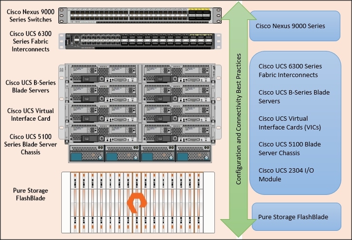
As shown in Figure 1, FlashStack Architecture can maintain consistency at scale. Each of the component families shown in (Cisco UCS, Cisco Nexus, Cisco FI and Pure Storage) offers platform and resource options to scale the infrastructure up or down, while supporting the same features and functionality that are required under the configuration and connectivity best practices of FlashStack.
FlashStack Solution Benefits
FlashStack provides a jointly supported solution by Cisco and Pure Storage. Bringing a carefully validated architecture built on superior compute, world-class networking, and the leading innovations in all flash storage. The portfolio of validated offerings from FlashStack includes but is not limited to the following:
· Consistent Performance and Scalability
- Consistent performance including bandwidth and latencies with all flash storage
- Consolidate hundreds of enterprise-class applications in a single rack
- Scalability design with capability to scale I/O bandwidth to match demand without disruption
- Repeatable growth through multiple FlashStack CI deployments.
· Operational Simplicity
- Fully tested, validated, and documented for rapid deployment
- Reduced management complexity
- No storage tuning or tiers necessary
· Lowest TCO
- Dramatic savings in power, cooling and space with Cisco UCS and 100 percent Flash
· Mission Critical and Enterprise Grade Resiliency
- Highly available architecture with no single point of failure
- Non-disruptive operations with no downtime
- Upgrade and expand without downtime or performance loss
- Native data protection including snapshots
Cisco and Pure Storage have also built a robust and experienced support team focused on FlashStack solutions, from customer account and technical sales representatives to professional services and technical support engineers. The support alliance between Pure Storage and Cisco gives customers and channel services partners direct access to technical experts who collaborate with cross vendors and have access to shared lab resources to resolve potential issues.
Solution Summary
Oracle data warehouse deployments are extremely complicated in nature and customers face enormous challenges in maintaining these landscapes in terms of data scale, time, efforts and cost. Oracle RAC databases often manage the mission critical components of a customer’s IT department, ensuring availability while also lowering the IT TCO is always their top priority. A storage platform based on Oracle data warehouse and analytics solutions supported by an all-flash storage solution, such as Pure Storage FlashBlade, can help you solve the challenges of data warehousing, management, and analysis — no matter where your data is stored.
A data warehouse is a relational or multidimensional database that is designed for query and analysis. Data warehouses usually consolidate historical and analytic data derived from multiple sources in one single place. This data is used for creating analytical reports for workers throughout the enterprise. The data in a data warehouse is typically loaded through an extraction, transformation, and loading (ETL) process from one or more data sources such as OLTP applications, mainframe applications, or external data providers.
Users of the data warehouse perform data analyses that are often time-related. Data warehouses are typically used to optimize business operations. Typical operations on a data warehouse include trend analysis and data mining, which use existing data to forecast trends or predict futures. The data warehouse typically provides the foundation for a business intelligence environment.
Storage configurations for a data warehouse should be chosen based on the I/O bandwidth that they can provide, and not necessarily on their overall storage capacity.
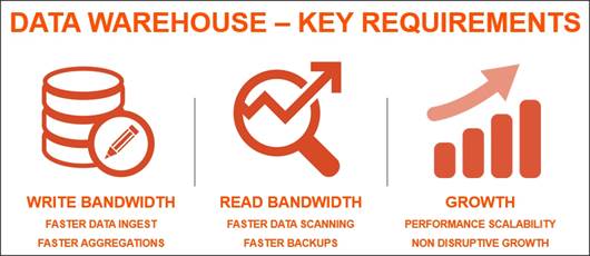
To implement successful data warehouse solution, there are three metric considerations:
· Write Bandwidth: Ability to quickly create and populate data warehouse or loading additional data for various data sources can challenge IO subsystem with sustained writes
· Read Bandwidth: Complex queries and analysis will require a huge amount of data reads.
· Growth: Growth of a data warehouse is inevitable, so a solution must be able to scale, and scale predictably, with that growth.
Considering such characteristics, we heavily emphasized on write and read bandwidth by running FIO and Swingbench performance test on this configured solution.
We will also demonstrate that this solution can scale with near-linear performance and provides a flexible platform for growth as needed on-demand.
The reference architecture covered in this document leverages the Pure Storage FlashBlade for Storage, Cisco UCS B200 M5 Blade Server for Compute, Cisco Nexus 9000 series for the switching element and Cisco Fabric Interconnects 6300 series for System Management. This solution is architected to modernize Oracle data warehouse by delivering performance you need to keep up with the data growth.
As shown in Figure 2, these components are connected and configured according to best practices of both Cisco and Pure Storage and provide the ideal platform for running a variety of enterprise database workloads with confidence.
FlashStack can scale up for greater performance and capacity (adding compute, network, or storage resources individually as needed), or it can scale out for environments that require multiple consistent deployments.
What’s New in this FlashStack Release?
This version of the FlashStack CVD introduces new hardware with the Pure Storage FlashBlade which is industry's most advanced file and object storage platform ever along with Cisco UCS B200 M5 Blade Servers featuring the Intel Xeon Scalable Family of CPUs. This is the third Oracle RAC Database deployment Cisco Validated Design with Pure Storage. It incorporates the following features:
· Pure Storage FlashBlade
· Cisco UCS B200 M5 Blade Servers
· Oracle RAC Database 12c Release 2
· Oracle Direct NFS
Cisco UCS 6332-16UP Fabric Interconnect
The 6332-16UP Fabric Interconnect is the management and communication backbone for Cisco UCS B-Series Blade Servers, C-Series Rack Servers, and 5100 Series Blade Server Chassis. It implements 20x40 Gigabit Ethernet and Fibre Channel over Ethernet ports, with additional support for 16 unified ports that can be configured to 1 or 10 Gbps Ethernet, or 4/8/16 Gbps Fibre Channel.

The Fabric Interconnect provides high-speed upstream connectivity to the network, or converged traffic to servers through its 40 Gbps ports, but also allows for Fibre Channel connectivity to SAN switches like the MDS, or alternately directly attached Fibre Channel to storage arrays like the Pure Storage FlashArray through its unified ports.
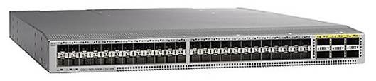
Cisco Nexus 9372PX-E Switch
The Cisco Nexus 9372PX-E Switches are 1RU switches that support 1.44 Tbps of bandwidth and over 1150 mpps across 48 fixed 10-Gbps SFP+ ports and 6 fixed 40-Gbps QSFP+ ports.
Cisco UCS B200 M5 Blade Servers
The Cisco UCS B200 M5 Blade Server delivers performance, flexibility, and optimization for deployments in data centers, in the cloud, and at remote sites. This enterprise-class server offers market-leading performance, versatility, and density without compromise for workloads including Virtual Desktop Infrastructure (VDI), web infrastructure, distributed databases, converged infrastructure, and enterprise applications and databases including Oracle.
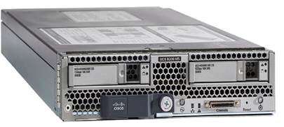
The Cisco UCS B200 M5 server can quickly deploy stateless physical and virtual workloads through programmable, easy-to-use Cisco UCS Manager Software and simplified server access through Cisco Single-Connect technology.
Cisco UCS 5108 Blade Server Chassis
Cisco UCS 5108 Blade Server Chassis, is six rack units (6RU) high, can mount in an industry-standard 19-inch rack, and uses standard front-to-back cooling. A chassis can accommodate up to eight half-width or four full-width Cisco UCS B-Series Blade Servers form factors within the same chassis.
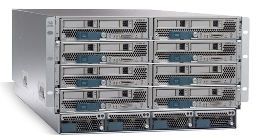
By incorporating unified fabric and fabric-extender technology, the Cisco Unified Computing System eliminates the need for dedicated chassis management and blade switches, reduces cabling, and allowing scalability to 20 chassis without adding complexity. The Cisco UCS 5108 Blade Server Chassis is a critical component in delivering the simplicity and IT responsiveness for the data center as part of the Cisco Unified Computing System.
Cisco UCS 2304 Fabric Extender
Cisco UCS 2304 Fabric Extender brings the unified fabric into the blade server enclosure, providing multiple 40 Gigabit Ethernet connections between blade servers and the fabric interconnect, simplifying diagnostics, cabling, and management.

The Cisco UCS 2304 connects the I/O fabric between the Cisco UCS 6300 Series Fabric Interconnects and the Cisco UCS 5100 Series Blade Server Chassis, enabling a lossless and deterministic Fibre Channel over Ethernet (FCoE) fabric to connect all blades and chassis together.
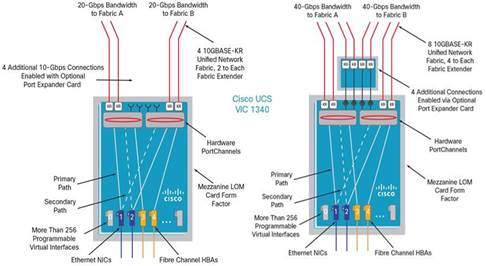
Cisco UCS Virtual Interface Card (VIC) 1340
The Cisco UCS Virtual Interface Card (VIC) 1340 is a 2-port 40-Gbps Ethernet or dual 4 x 10-Gbps Ethernet, Fibre Channel over Ethernet (FCoE)-capable modular LAN on motherboard (mLOM) designed for the Cisco UCS B-Series Blade Servers. When used in combination with an optional port expander, the Cisco UCS VIC 1340 capabilities is enabled for two ports of 40-Gbps Ethernet.

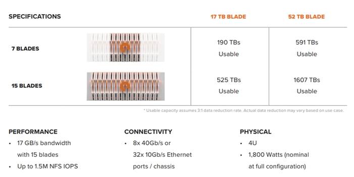
Pure Storage FlashBlade
FlashBlade™ is a new scale-out storage platform designed to accelerate data-intensive applications, like modern analytics, data warehouse, and AI, while providing best of breed performance in all dimensions of concurrency – including IOPS, throughput, latency, and capacity. FlashBlade is as simple as it is powerful, offering elastic scale-out storage services at every layer alongside DirectFlash technology for global flash management.
FlashBlade is the industry’s first to deliver modern file and object on a single platform, delivering unprecedented performance for all data-intensive applications. Its massively distributed architecture enables consistent performance for all analytics applications using NFS, S3/Object, SMB, and HTTP protocols.
FlashBlade delivers industry-leading throughput, IOPS, latency, and capacity – in 20x less space and 10x less power and cooling. FlashBlade is built on the scale-out metadata architecture of Purity for FlashBlade, capable of handling ten’s of billions of files and objects while delivering maximum performance, effortless scale, and global flash management. The distributed transaction database built into the core of Purity means storage services at every layer are elastic: simply adding blades grows system capacity and performance, instantly. It also offers a wave of new enterprise features, like snapshots, SMB, LDAP, network lock management (NLM), and IPv6, to extend FlashBlade into new use cases.
Figure 3Pure Storage FlashBlade

Pure1®, our cloud-based management, analytics, and support platform, expands the self-managing, plug-n-play design of our products with the machine learning predictive analytics and continuous scanning of Pure1 Meta™ to enable an effortless, worry-free storage experience.
For the first time in the industry, Pure1 Analyze delivers true performance forecasting – giving customers complete visibility into the performance and capacity needs of their arrays – now and in the future. Performance forecasting enables intelligent consolidation and unprecedented workload optimization.
Figure 4FlashBlade Specification
The Evergreen™ Storage ownership model operates like SaaS and the cloud. Deploy storage once and benefit from a subscription to continuous innovation as you expand and improve performance, capacity, density, and/or features for 10 years or more – all without downtime, performance impact, or data migrations. Evergreen Storage provides expandability and upgradability for generations via its modular, stateless architecture, while FlashBlade’s blade-based design delivers the linear scale of DirectFlash technology and compute simply by adding blades.
Oracle Linux 7.4
Oracle Linux, formerly known as Oracle Enterprise Linux, is a Linux distribution based on Red Hat Enterprise Linux (RHEL), repackaged and freely distributed by Oracle, available under GNU General Public License (GPL) since late 2006. Oracle Linux can be downloaded through Oracle’s E-Delivery service or from a variety of mirror sites, and can be deployed and distributed freely. Commercial technical support is available through Oracle’s Oracle Linux Support program, which supports Oracle Linux, and existing RHEL or CentOS installation.
Oracle Corporation distributes Oracle Linux with two alternative kernels:
· Red Hat Compatible Kernel (RHCK) – identical to the kernel shipped in Red Hat Enterprise Linux
· Unbreakable Enterprise Kernel (UEK) – based on newer mainline Linux kernel versions, with Oracle’s own enhancements for OLTP, Infiniband, and SSD disk access, NUMA-optimizations, Reliable Datagram Sockets (RDS), async I/O, OCFS2, and networking.
Oracle Linux Support Program provides support for KVM components as part of the Oracle Linux 5, Oracle Linux 6, Oracle Linux 7, RHEL5, RHEL6, and RHEL7. This does not include Oracle Product support on KVM offerings.
Oracle 12cR2 Database
Oracle revolutionized the field of enterprise database management systems with the most extensive self-management capabilities in the industry, ranging from zero-overhead instrumentation to integrated self-healing and business-driven management. Oracle Database 12c, the next generation of the world’s most popular database, makes DBA lives easier by providing various features like change and configuration management, patching, provisioning, testing, performance management, and automatic tuning. Oracle Database high-availability (HA) technologies, collectively referred to as Oracle Maximum Availability Architecture (MAA), provide complete resiliency against all types of outages – from component failures to natural disasters. Industry-leading Oracle HA technology such as Oracle Real Application Clusters (Oracle RAC) provides the highest levels of server HA while Oracle Active Data Guard protects data and applications against site-wide outages.
The FlashStack solution for Oracle includes the following Oracle 12c components and/or features:
· Oracle Database 12c Release 2 (12.2.0.1) Enterprise Edition
· Oracle Grid Infrastructure 12c (12.2.0.1)
· Oracle Flex ASM & ASM Cluster File System (ACFS)
· Oracle Direct NFS Client
Oracle dNFS (direct Network File System)
Oracle dNFS (direct Network File System) is the NFS client functionality directly integrated in the Oracle RDBMS server. dNFS makes the task of configuring Oracle database on NAS storage much simpler compared to Standard NFS (aka Kernel NFS). Direct NFS Client on Oracle 11g, 12c, or higher supports NFSv3, NFSv4, and NFSv4.1 protocols to access the NFS server.
The key benefits of Direct NFS Client include simplicity, ease of administration, load balancing, high availability and cost effectiveness. Oracle has optimized the I/O code path by avoiding kernel overhead and, as such, it can improve I/O performance.
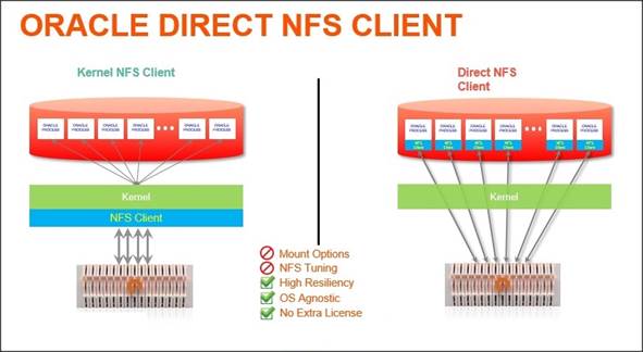
Direct NFS Client is capable of performing concurrent direct I/O by bypassing Operating System level caches. It also performs asynchronous I/O, which allows processing to continue while the I/O request is submitted and processed. These two key performance and scalability features provide unparalleled performance when compared to native kernel NFS clients. Another key feature of Direct NFS Client is high availability. Direct NFS Client delivers optimized performance by automatically load balancing requests across all specified paths (up to 4 parallel network paths). If one network path fails, then Direct NFS Client will reissue I/O commands over any remaining paths, ensuring fault tolerance and high availability.
One of the primary challenges of kernel NFS administration is inconsistency with configurations across different platforms. Direct NFS Client eliminates this problem by providing a standard NFS client implementation across all platforms supported by Oracle Database. This also makes NFS a viable option on platforms like Windows, which doesn’t natively support NFS. As NFS is a shared file system, it supports Real Application Cluster (RAC) databases as well as single-instance databases. Oracle Direct NFS Client recognizes when an instance is part of an RAC and automatically optimizes the mount points for RAC, relieving the administrator of manually configuring the NFS parameters.
Solution Architecture
The FlashStack architecture brings together the proven data center strengths of the Cisco UCS and Cisco Nexus network switches with the NFS delivered storage of the leading visionary in all flash arrays. This collaboration creates a simple, yet powerful and resilient data center footprint for the modern enterprise. The FlashStack Data Center with Oracle RAC database on Oracle Linux solution provides an end-to-end architecture with Cisco, Oracle, and Pure Storage technologies and demonstrates the FlashStack configuration benefits for running highly available Oracle RAC Database 12c R2 with Cisco VICs (Virtual Interface Cards).
Physical Topology
FlashStack consists of a combined stack of hardware (storage, network and compute) and software (Cisco UCS Manager, Oracle Database, Pure Storage GUI, Purity, and Oracle Linux).
· Network: Cisco Nexus 9372PX-E and Cisco UCS Fabric Interconnect 6332-16UP for external and internal connectivity of IP network.
· Storage: Pure Storage FlashBlade with 40Gb Ethernet connectivity
· Compute: Cisco UCS B200 M5 Blade Server
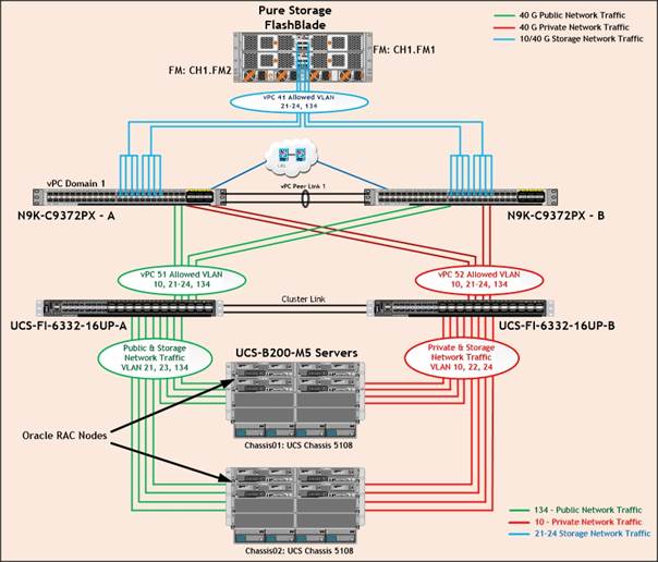
Figure 5 illustrates the FlashStack solution physical infrastructure.
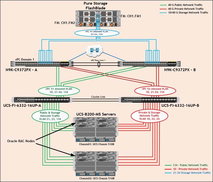
Figure 5 is a typical network configuration that can be deployed in a customer's environment. The best practices and setup recommendations are described later in this document.
As shown in Figure 5, a pair of Cisco UCS 6332-16UP Fabric Interconnects carries both storage and network traffic from the server blades with the help of Cisco Nexus 9372PX-E switches. Both the Fabric Interconnect and the Cisco Nexus switch are clustered with the peer link between them to provide high availability. Three virtual Port-Channels (vPCs) are configured to provide public network, private network and storage network paths for the server blades to northbound switches and storage. Each vPC has VLANs created for application network data, storage data and management data paths.
As illustrated in in Figure 5, eight (4 x 40G link per chassis) links go to Fabric Interconnect – A. Similarly, eight links go to Fabric Interconnect – B. Fabric Interconnect – A links are used for Oracle Public Network Traffic (VLAN-134) and Storage Network Traffic (VLAN-21 & 23) shown as green lines. Fabric Interconnect – B links are used for Oracle Private Interconnect Traffic (VLAN 10) and Storage Network Traffic (VLAN-22 & 24) shown as red lines. NFS Storage access from Nexus Switch – A and Nexus Switch –B show as blue lines.
![]() For Oracle RAC configuration on Cisco Unified Computing System, we recommend to keep all private interconnects local on a single Fabric interconnect. In this case, the private traffic stays local to that fabric interconnects and will not be routed via northbound network switch. All inter-server blade (or RAC node private) communication will be resolved locally at the fabric interconnect and this significantly reduces latency for Oracle Cache Fusion traffic.
For Oracle RAC configuration on Cisco Unified Computing System, we recommend to keep all private interconnects local on a single Fabric interconnect. In this case, the private traffic stays local to that fabric interconnects and will not be routed via northbound network switch. All inter-server blade (or RAC node private) communication will be resolved locally at the fabric interconnect and this significantly reduces latency for Oracle Cache Fusion traffic.
Design Topology
This section describes the design considerations for the Oracle RAC Database 12c Release 2 on FlashStack deployment. In this solution design, we used two Cisco UCS Blade Server Chassis with 8 identical Intel Xeon CPU based Cisco UCS B-Series B200 M5 Blade Servers for hosting the 8-Node Oracle RAC 12cR2 Databases. The Cisco UCS B200 M5 Server has Virtual Interface Card (VIC) 1340 with port expander and they were connected four ports from each Cisco Fabric extender of the Cisco UCS Chassis to the Cisco Fabric Interconnects, which were in turn connected to the Cisco Nexus Switches for upstream connectivity to access the Pure Storage FlashBlade.
Table 1 lists the inventory of the components used in the FlashStack solution.
Table 1 Inventory and Bill of Materials
| Vendor | Name | Model | Description | Qty |
| Cisco | Cisco Nexus 9372PX-E Switch | N9K-C9372PX-E | Cisco Nexus 9300 Series Switches | 2 |
| Cisco | Cisco UCS 6332-16UP Fabric Interconnect | UCS-FI-6332-16UP | Cisco 6300 Series Fabric Interconnects | 2 |
| Cisco | Cisco UCS Fabric Extender | UCS-IOM-2304 | Cisco UCS 2304XP I/O Module (4 External, 8 Internal 40Gb Ports) | 4 |
| Cisco | Cisco UCS 5108 Blade Server Chassis | UCSB-5108-AC2 | Cisco UCS 5100 Series Blade Server AC2 Chassis | 2 |
| Cisco | Cisco UCS B200 M5 Blade Servers | UCSB-B200-M5 | Cisco UCS B-Series Blade Servers | 8 |
| Cisco | Cisco UCS VIC 1340 | UCSB-MLOM-40G-03 | Cisco UCS Virtual Interface Card 1340 | 8 |
| Cisco | Cisco UCS Port Expander Card | UCSB-MLOM-PT-01 | Port Expander Card for Cisco UCS MLOM | 8 |
| Pure Storage | Pure FlashBlade | Purity //FB 2.1.8 | Pure Storage FlashBlade | 1 |
Table 2 lists the server configuration used in the FlashStack solution.
Table 2 Cisco UCS B200 M5 Blade Server Configuration
| Server Configuration | |
| Processor | 2 x Intel® Xeon® Gold 6152 Processor (2.10 GHz, 140W, 22C, 30.25MB Cache, DDR4 2666MHz 768GB) |
| Memory | 16 x 32GB DDR4-2666-MHz RDIMM/dual rank/x4/1.2v |
| Cisco UCS VIC 1340 | Cisco UCS VIC 1340 Blade MLOM |
| Cisco UCS Port Expander Card | Port Expander Card for Cisco UCS MLOM |
| NIC1 (eth0) | Management and Public Network Traffic Interface for Oracle RAC. MTU=1500 |
| NIC2 (eth1) | Private Server-to-Server Network (Cache Fusion) Traffic Interface for Oracle RAC. MTU=9000 |
| NIC3 (eth2) | Database IO Traffic to Pure Storage FlashBlade. Controller VLAN 21. MTU=9000 |
| NIC4 (eth3) | Database IO Traffic to Pure Storage FlashBlade. Controller VLAN 22. MTU=9000 |
| NIC5 (eth4) | Database IO Traffic to Pure Storage FlashBlade. Controller VLAN 23. MTU=9000 |
| NIC6 (eth5) | Database IO Traffic to Pure Storage FlashBlade. Controller VLAN 24. MTU=9000 |
![]() For this FlashStack solution design, we configured six VLANs as described in Table 3 .
For this FlashStack solution design, we configured six VLANs as described in Table 3 .
Table 3 VLAN and VSAN Configuration
| VLANs | ||
| Name | ID | Description |
| Default VLAN | 1 | Native VLAN |
| Public VLAN | 134 | VLAN for Public Network Traffic |
| Private VLAN | 10 | VLAN for Private Network Traffic (RAC Interconnect) |
| Storage VLAN - 21 | 21 | NFS VLAN for Storage Network Traffic A Side |
| Storage VLAN - 22 | 22 | NFS VLAN for Storage Network Traffic B Side |
| Storage VLAN - 23 | 23 | NFS VLAN for Storage Network Traffic A Side |
| Storage VLAN - 24 | 24 | NFS VLAN for Storage Network Traffic B Side |
The FlashStack design comprises of Pure Storage FlashBlade enterprise class all-flash for increased scalability and throughput. Table 4 lists the components of the array.
Table 4 Pure Storage FlashBlade Configuration
| Storage Components | Description |
| FlashBlade | Pure Storage FlashBlade |
| Capacity | 162.46 TB |
| Connectivity | 8 x 40 Gb/s redundant Ethernet port |
| Physical | 4U |
For this FlashStack solution design, we used the Software and Firmware listed in Table 5 .
Table 5 Software and Firmware Configuration
| Software and Firmware | Version |
| Oracle Linux Server 7.4 (64 bit) Operating System | Linux 4.1.12-94.3.9.el7uek.x86_64 |
| Oracle 12c Release 2 GRID | 12.2.0.1.0 |
| Oracle 12c Release 2 Database Enterprise Edition | 12.2.0.1.0 |
| Cisco Nexus 9372PX-E NXOS Version | 6.1(2) I2 (2a) |
| Cisco UCS Manager System | 3.2 (2c) |
| Cisco UCS Adapter VIC 1340 | 4.2 (2b) |
| Cisco eNIC (modinfo enic) | 2.3.0.31 |
| Pure Storage FB Purity Version | 2.1.8 |
| Oracle Swingbench | 2.5.971 |
| TPC-H |
|
| FIO | fio-2.1.10-1.el7.rf.x86_64 |
Cisco UCS Configuration Overview
This section details the Cisco UCS configuration that was done as part of the infrastructure build out. The racking, power, and installation of the chassis are described in the installation guide www.cisco.com/c/en/us/support/servers-unified-computing/ucs-manager/products-installation-guides-list.html.
![]() It is beyond the scope of this document to cover detailed information about Cisco UCS infrastructure setup and connectivity. The documentation guides and examples are available at http://www.cisco.com/en/US/products/ps10281/products_installation_and_configuration_guides_list.html.
It is beyond the scope of this document to cover detailed information about Cisco UCS infrastructure setup and connectivity. The documentation guides and examples are available at http://www.cisco.com/en/US/products/ps10281/products_installation_and_configuration_guides_list.html.
![]() All of the tasks to configure Cisco UCS are detailed in this document, but only some of the screenshots are included.
All of the tasks to configure Cisco UCS are detailed in this document, but only some of the screenshots are included.
Cisco UCS Manager Software Version 3.2 (2c)
This document assumes you are using Cisco UCS Manager Software version 3.2(2c). To upgrade the Cisco UCS Manager software and the Cisco UCS 6332-16UP Fabric Interconnect software to a higher version of the firmware, refer to Cisco UCS Manager Install and Upgrade Guides.
Configure Base Cisco Unified Computing System
The following are the high-level steps involved for a Cisco UCS configuration:
1. Configure Fabric Interconnects for a Cluster Setup.
2. Set Fabric Interconnects to Fibre Channel End Host Mode.
3. Synchronize Cisco UCS to NTP.
4. Configure Fabric Interconnects for Chassis and Blade Discovery:
a. Configure Global Policies
b. Configure Server Ports
5. Configure LAN on Cisco UCS Manager:
a. Configure Ethernet LAN Uplink Ports
b. Create Uplink Port Channels to Cisco Nexus Switches
c. Configure VLAN
6. Configure IP, UUID, Server and MAC Pools:
a. IP Pool Creation
b. UUID Suffix Pool Creation
c. Server Pool Creation
d. MAC Pool Creation
7. Set Jumbo Frames in both the Cisco Fabric Interconnect.
8. Configure Server BIOS Policy.
9. Create Adapter Policy.
10. Configure Update Default Maintenance Policy.
11. Configure vNIC Template:
a. Create Public vNIC Template
b. Create Private vNIC Template
c. Create Storage vNIC Template
12. Create Server Boot Policy for Local Boot
Details for each step are discussed in the following sections.
Configure Fabric Interconnects for a Cluster Setup
To configure the Cisco UCS Fabric Interconnects, complete the following steps:
1. Verify the following physical connections on the fabric interconnect:
a. The management Ethernet port (mgmt0) is connected to an external hub, switch, or router
b. The L1 ports on both fabric interconnects are directly connected to each other
c. The L2 ports on both fabric interconnects are directly connected to each other
![]() For more information, refer to the Cisco UCS Hardware Installation Guide for your fabric interconnect.
For more information, refer to the Cisco UCS Hardware Installation Guide for your fabric interconnect.
2. Connect to the console port on the first Fabric Interconnect.
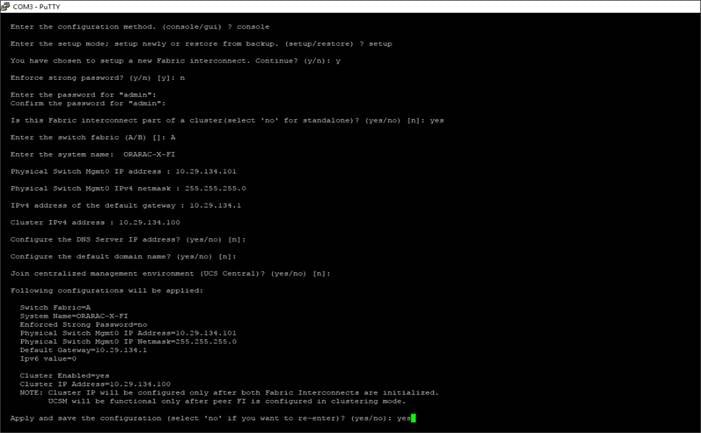
3. Review the settings on the console. Answer yes to Apply and Save the configuration.
4. Wait for the login prompt to make sure the configuration has been saved to Fabric Interconnect A.
5. Connect the console port on the second Fabric Interconnect and do as follows:
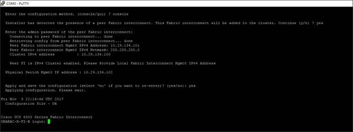
6. Review the settings on the console. Answer yes to Apply and Save the configuration.
7. Wait for the login prompt to make sure the configuration has been saved to Fabric Interconnect B.
To log into the Cisco Unified Computing System (Cisco UCS) environment, complete the following steps:
1. Open a web browser and navigate to the Cisco UCS Fabric Interconnect cluster address configured above.
2. Click the Launch UCS Manager link to download the Cisco UCS Manager software.
3. If prompted, accept the security certificates.
4. When prompted, enter the user name and password enter the password.
5. Click “Log In” to log into Cisco UCS Manager.
Set Fabric Interconnects to Fibre Channel End Host Mode
To set the Fabric Interconnects to the Fibre Channel End Host Mode, complete the following steps:
1. On the Equipment tab, expand the Fabric Interconnects node and click Fabric Interconnect A.
2. On the General tab in the Actions pane, click Set FC End Host mode.
3. Follow the dialogs to complete the change.
![]() Both Fabric Interconnects automatically reboot sequentially when you confirm you want to operate in this mode.
Both Fabric Interconnects automatically reboot sequentially when you confirm you want to operate in this mode.
Synchronize Cisco UCS to NTP
To synchronize the Cisco UCS environment to the NTP server, complete the following steps:
1. In Cisco UCS Manager, in the navigation pane, click the Admin tab.
2. Select All > Time zone Management.
3. In the Properties pane, select the appropriate time zone in the Time zone menu.
4. Click Save Changes and then click OK.
5. Click Add NTP Server.
6. Enter the NTP server IP address and click OK.
7. Click OK to finish.
Configure Fabric Interconnects for Chassis and Blade Discovery
Cisco UCS 6332-16UP Fabric Interconnects are configured for redundancy. It provides resiliency in case of failures. The first step is to establish connectivity between blades and Fabric Interconnects.
Configure Global Policies
The chassis discovery policy determines how the system reacts when you add a new chassis. We recommend using the platform max value as shown. Using platform max helps ensure that Cisco UCS Manager uses the maximum number of IOM uplinks available.
To configure global policies, complete the following steps:
1. Go to Equipment > Policies (right pane) > Global Policies > Chassis/FEX Discovery Policies. As shown in the screenshot below, select Action as “Platform Max” from the drop-down list and set Link Grouping to Port Channel.
2. Click Save Changes.
3. Click OK.
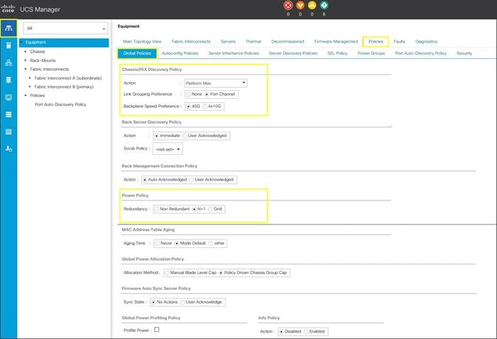
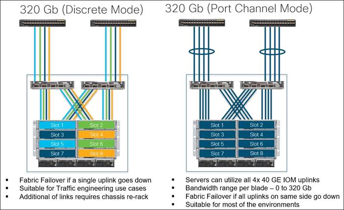
Figure 6 illustrates the advantage of having Discrete mode versus Port Channel mode.
Figure 6Fabric Ports: Discrete vs. Port Channel Mode
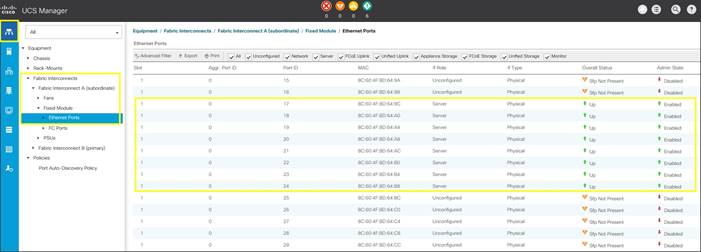
Configure Server Ports
Configure Server Ports to initiate Chassis and Blade discovery. To configure server ports, complete the following steps:
1. Go to Equipment > Fabric Interconnects > Fabric Interconnect A > Fixed Module > Ethernet Ports.
2. Select the ports (for this solution ports are 17-24) which are connected to the Cisco IO Modules of the two B-Series 5108 Chassis.
3. Right-click and select “Configure as Server Port.”
4. Click Yes to confirm and click OK.
5. Repeat the steps above for Fabric Interconnect B.
6. After configuring Server Ports, acknowledge both the Chassis. Go to Equipment >Chassis > Chassis 1 > General > Actions > select “Acknowledge Chassis”. Similarly, acknowledge the chassis 2.
7. After acknowledging both the chassis, re-acknowledge all the servers placed in the chassis. Go to Equipment > Chassis 1 > Servers > Server 1 > General > Actions > select Server Maintenance > select option “Re-acknowledge” and click OK. Repeat this process to re-acknowledge all eight Servers.
8. When the acknowledgement of the Servers is completed, verify the Port-channel of Internal LAN. Go to the LAN tab > Internal LAN > Internal Fabric A > Port Channels as shown in the screenshot below.
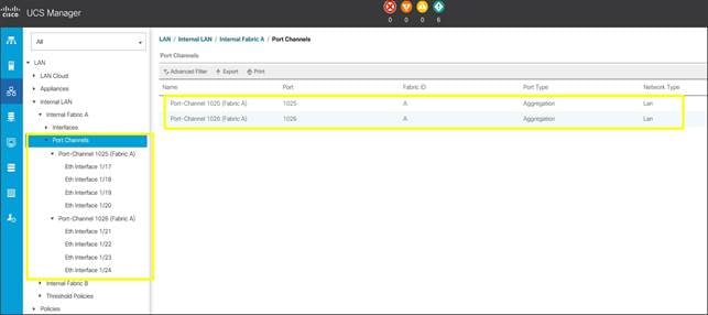
9. Repeat these steps for Internal Fabric B.
Configure LAN on Cisco UCS Manager
Configure Ethernet Uplink Ports as explained in the following section.
Configure Ethernet LAN Uplink Ports
To configure network ports used to uplink the Fabric Interconnects to the Cisco Nexus switches, complete the following steps:
1. In Cisco UCS Manager, in the navigation pane, click the Equipment tab.
2. Select Equipment > Fabric Interconnects > Fabric Interconnect A > Fixed Module.
3. Expand Ethernet Ports.
4. Select ports (for this solution ports are 11-14) that are connected to the Nexus switches, right-click them, and select Configure as Network Port.
5. Click Yes to confirm ports and click OK.
6. Verify the Ports connected to Cisco Nexus upstream switches are now configured as network ports.
7. Repeat the above steps for Fabric Interconnect B. The screenshot below shows the network uplink ports for Fabric A.
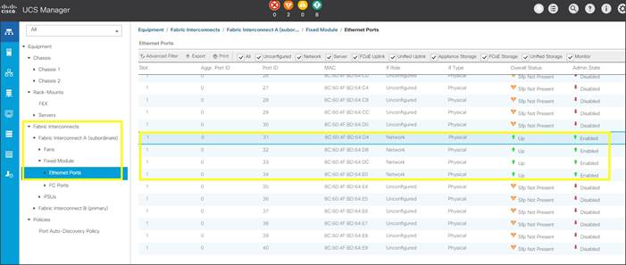
You have now created four uplink ports on each Fabric Interconnect as shown above. These ports will be used to create Virtual Port Channel in the next section.
Create Uplink Port Channels to Cisco Nexus Switches
In this procedure, two port channels were created; one from Fabric A to both Cisco Nexus 9372PX-E switches and one from Fabric B to both Cisco Nexus 9372PX-E switches. To configure the necessary port channels in the Cisco UCS environment, complete the following steps:
1. In Cisco UCS Manager, click the LAN tab in the navigation pane.
2. Under LAN > LAN Cloud, expand node Fabric A tree:
a. Right-click Port Channels.
b. Select Create Port Channel.
c. Enter 51 as the unique ID of the port channel.
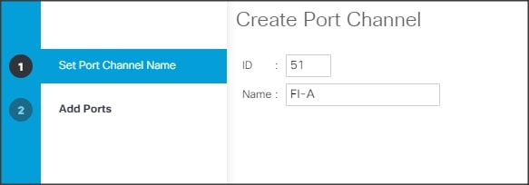
d. Enter FI-A as the name of the port channel.
e. Click Next.
f. Select Ethernet ports 31-34 for the port channel.
3. Click Finish.
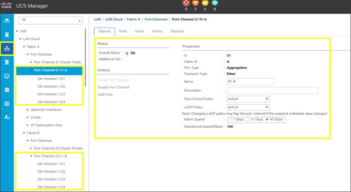
4. Repeat steps 1-3 for Fabric Interconnect B, substituting 52 for the port channel number and FI-B for the name. Your resulting configuration should look like the screenshot above.
Configure VLAN
To configure the necessary virtual local area networks (VLANs) for the Cisco UCS environment, complete the following steps:
1. In Cisco UCS Manager, click the LAN tab in the navigation pane.
![]() In this solution, we created six VLANs: one for private network (VLAN 10) traffic, one for public network (VLAN 134) traffic and four storage network (VLAN 21, 22, 23 and 24) traffic. These six VLANs will be used in the vNIC templates that are discussed later.
In this solution, we created six VLANs: one for private network (VLAN 10) traffic, one for public network (VLAN 134) traffic and four storage network (VLAN 21, 22, 23 and 24) traffic. These six VLANs will be used in the vNIC templates that are discussed later.
![]() It is very important to create all six VLANs as global across both fabric interconnects. This way, VLAN identity is maintained across the fabric interconnects in case of NIC failover.
It is very important to create all six VLANs as global across both fabric interconnects. This way, VLAN identity is maintained across the fabric interconnects in case of NIC failover.
2. Select LAN > LAN Cloud.
3. Right-click VLANs.
4. Select Create VLANs.
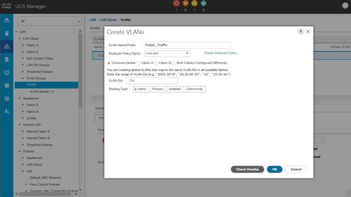
5. Enter Public_Traffic as the name of the VLAN to be used for Public Network Traffic.
6. Keep the Common/Global option selected for the scope of the VLAN.
7. Enter 134 as the ID of the VLAN ID.
8. Keep the Sharing Type as None.
9. Click OK and then click OK again.
10. Similarly, we have created the second VLAN: for private network (VLAN 10) traffic and remaining four storage VLANs for storage network (VALN 21, 22, 23 & 24) traffic as shown below:
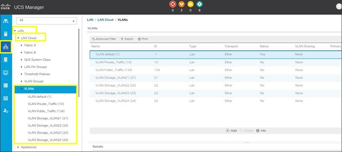
![]() These six VLANs will be used in the vNIC templates that are discussed later.
These six VLANs will be used in the vNIC templates that are discussed later.
Configure IP, UUID, Server and MAC Pools
IP Pool Creation
An IP address pool on the out of band management network must be created to facilitate KVM access to each compute node in the Cisco UCS domain. To create a block of IP addresses for server KVM access in the Cisco UCS environment, complete the following steps:
1. In Cisco UCS Manager, in the navigation pane, click the LAN tab.
2. Select Pools > root > IP Pools > click Create IP Pool.
![]() We named the IP Pool as ORA-IP-Pool for this solution.
We named the IP Pool as ORA-IP-Pool for this solution.
3. Select option Sequential to assign IP in sequential order then click Next.
4. Click Add IPv4 Block.
5. Enter the starting IP address of the block and the number of IP addresses required, and the subnet and gateway information as shown in the screenshot.
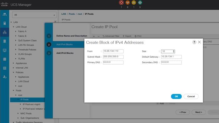
6. Click Next and then click Finish to create the IP block.
UUID Suffix Pool Creation
To configure the necessary universally unique identifier (UUID) suffix pool for the Cisco UCS environment, complete the following steps:
1. In Cisco UCS Manager, click the Servers tab in the navigation pane.
2. Select Pools > root.
3. Right-click UUID Suffix Pools and then select Create UUID Suffix Pool.
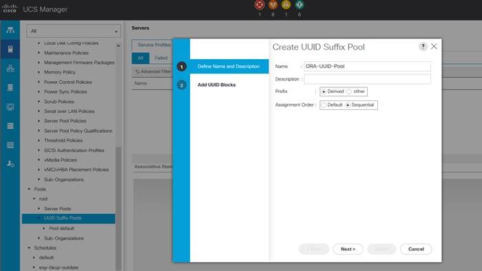
4. Enter ORA-UUID-Pool as the name of the UUID name.
5. Optional: Enter a description for the UUID pool.
6. Keep the prefix at the derived option and select Sequential in as Assignment Order then click Next.
7. Click Add to add a block of UUIDs.
8. Create a starting point UUID as per your environment.
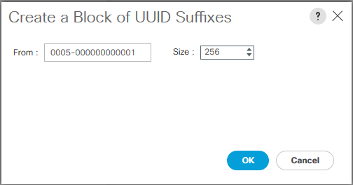
9. Specify a size for the UUID block that is sufficient to support the available blade or server resources.
Server Pool Creation
To configure the necessary server pool for the Cisco UCS environment, complete the following steps:
![]() Consider creating unique server pools to achieve the granularity that is required in your environment.
Consider creating unique server pools to achieve the granularity that is required in your environment.
1. In Cisco UCS Manager, click the Servers tab in the navigation pane.
2. Select Pools > root > right-click Server Pools > Select Create Server Pool.
3. Enter ORA-Pool as the name of the server pool.
4. Optional: Enter a description for the server pool then click Next.
5. Select all the eight servers to be used for the Oracle RAC management and click > to add them to the server pool.
6. Click Finish and then click OK.
MAC Pool Creation
To configure the necessary MAC address pools for the Cisco UCS environment, complete the following steps:
1. In Cisco UCS Manager, click the LAN tab in the navigation pane.
2. Select Pools > root > right-click MAC Pools under the root organization.
3. Select Create MAC Pool to create the MAC address pool.
4. Enter ORA-MAC-A as the name for MAC pool.
5. Enter the seed MAC address and provide the number of MAC addresses to be provisioned.
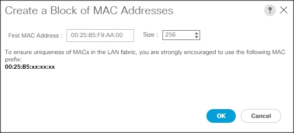
6. Click OK and then click Finish.
7. In the confirmation message, click OK.
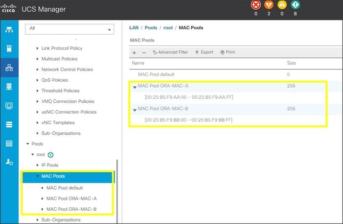
8. Create MAC Pool B and assign unique MAC Addresses as shown below.
![]() We created Oracle-MAC-A and Oracle-MAC-B as shown below for all the vNIC MAC Addresses.
We created Oracle-MAC-A and Oracle-MAC-B as shown below for all the vNIC MAC Addresses.
Set Jumbo Frames in both the Cisco Fabric Interconnect
To configure jumbo frames and enable quality of service in the Cisco UCS fabric, complete the following steps:
1. In Cisco UCS Manager, click the LAN tab in the navigation pane.
2. Select LAN > LAN Cloud > QoS System Class.
3. In the right pane, click the General tab.
4. On the Best Effort row, enter 9216 in the box under the MTU column.
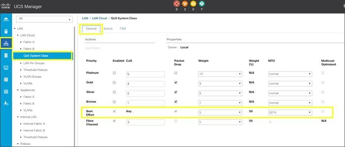
5. Click Save Changes.
6. Click OK.
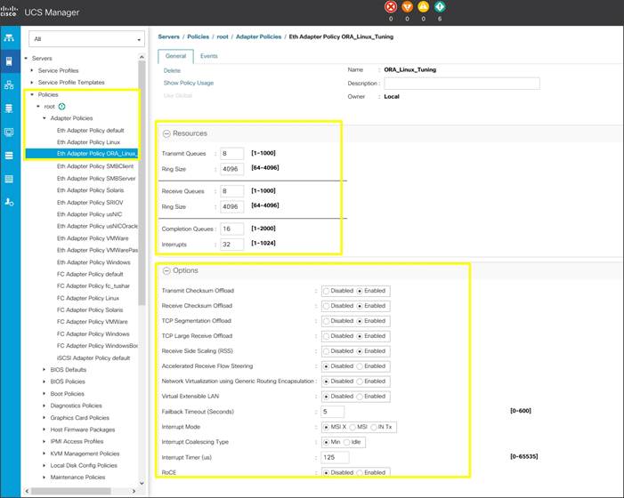
Create Adapter Policy
To create an Adapter Policy for the Cisco UCS environment, complete the following steps:
1. In Cisco UCS Manager, click the Servers tab in the navigation pane.
2. Select Policies > root > right-click Adapter Policies.
3. Select Create Ethernet Adapter Policy.
4. Provide a name for the Ethernet adapter policy. Change the following fields and click Save Changes when you are finished:
- Resources
§ Transmit Queues: 8
§ Ring Size: 4096
§ Receive Queues: 8
§ Ring Size: 4096
§ Completion Queues: 16
§ Interrupts: 32
- Options
§ Receive Side Scaling (RSS): Enabled
5. Configure adapter policy as shown below:
![]() RSS distributes network receive processing across multiple CPUs in multiprocessor systems. This can be one of the following:
RSS distributes network receive processing across multiple CPUs in multiprocessor systems. This can be one of the following:
· Disabled—Network receive processing is always handled by a single processor even if additional processors are available.
· Enabled—Network receive processing is shared across processors whenever possible.
6. Click OK to finish.
Configure Update Default Maintenance Policy
To update the default Maintenance Policy, complete the following steps:
In Cisco UCS Manager, click the Servers tab in the navigation pane.
1. Select Policies > root > Maintenance Policies > Default.
2. Change the Reboot Policy to User Ack.
3. Click Save Changes.
4. Click OK to accept the changes.
Configure vNIC Template
![]() We created six vNIC template for Public Network, Private Network and Storage Network Traffic. We will use these vNIC Templates during the creation of the Service Profile later in this section.
We created six vNIC template for Public Network, Private Network and Storage Network Traffic. We will use these vNIC Templates during the creation of the Service Profile later in this section.
Create Public, Private and Storage vNIC Template
To create vNIC (virtual network interface card) template for the Cisco UCS environment, complete the following steps:
1. In Cisco UCS Manager, click the LAN tab in the navigation pane.
2. Select Policies > root > vNIC Templates > right-click to vNIC Template and Select "Create vNIC Template"
3. Enter ORA-vNIC-A as the vNIC template name and keep Fabric A selected.
4. Select the Enable Failover checkbox for high availability of the vNIC.
5. Select Template Type as Updating Template.
6. Under VLANs, select the checkboxes default and Public_Traffic and set Native-VLAN as the Public_Traffic.
7. Keep MTU value 1500 for Public Network Traffic.
8. In the MAC Pool list, select ORA-MAC-A.
9. Click OK to create the vNIC template as shown below:
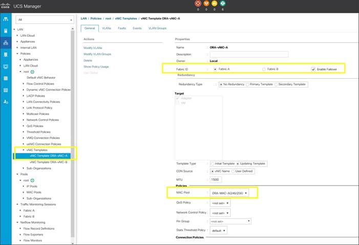
10. Click OK to finish.
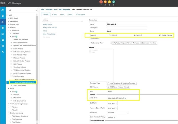
11. Create second vNIC template for Private Network Traffic.
12. Enter ORA-vNIC-B as the vNIC template name for Private Network Traffic.
13. Select the Fabric B and Enable Failover for Fabric ID options.
14. Select Template Type as Updating Template.
15. Under VLANs, select the checkbox Private_Traffic and set Native-VLAN as the Private_Traffic.
16. Set MTU value to 9000 and MAC Pool as ORA-MAC-B.
17. Click OK to create the vNIC template as shown below:
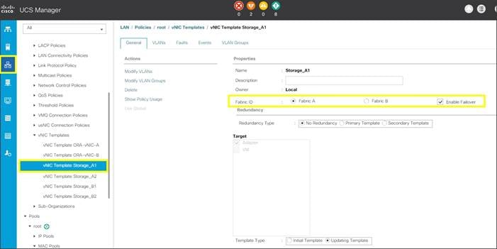
18. Create third vNIC template for Storage Network Traffic through Fabric Interconnect – A.
19. Enter Storage_A1 as the vNIC template name for Storage Network Traffic.
20. Select the Fabric A and Enable Failover for Fabric ID options.
21. Select Template Type as Updating Template.
22. Under VLANs, select the checkbox Storage_VLAN21 and set Native-VLAN as the Storage_VLAN21.
23. Set MTU value to 9000 and MAC Pool as ORA-MAC-A.
24. Click OK to create the vNIC template as shown below:
25. Similarly, create fourth vNIC template as Storage_A2 and set Native-VLAN as the Storage_VLAN23 and Click OK to create vNIC template.
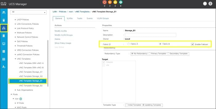
26. Now, create fifth vNIC template for Storage Network Traffic through Fabric Interconnect – B.
27. Enter Storage_B1 as the vNIC template name for Storage Network Traffic.
28. Select the Fabric B and Enable Failover for Fabric ID options.
29. Select Template Type as Updating Template.
30. Under VLANs, select the checkbox Storage_VLAN22 and set Native-VLAN as the Storage_VLAN22.
31. Set MTU value to 9000 and MAC Pool as ORA-MAC-B.
32. Click OK to create the vNIC template as shown below:
33. Similarly, create last sixth vNIC template as Storage_B2 and set Native-VLAN as the Storage_VLAN24. Click OK to create vNIC template.
34. All the vNIC templates are as shown below.
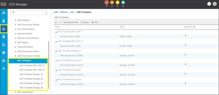
Create Server Boot Policy for Local Boot
All Oracle nodes were set to boot from Local Disk for this Cisco Validated Design as part of the Service Profile template. A Local disk configuration for the Cisco UCS is necessary if the servers in the environments have a local disk.
To create Boot Policies for the Cisco UCS environments, complete the following steps:
1. Go to Cisco UCS Manager and then go to Servers > Policies > root > Boot Policies.
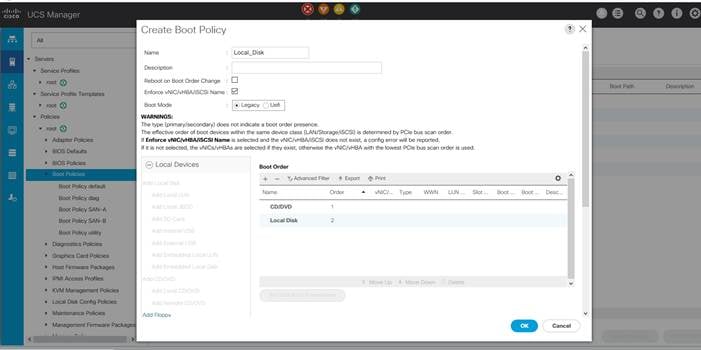
2. Right-click and select Create Boot Policy. Enter Local_Disk as the name of the boot policy as shown below:
3. Expand the Local Devices drop-down list and Choose Add CD/DVD and then Local Disk for the Boot Order as shown below.
Configure and Create a Service Profile Template
Service profile templates enable policy based server management that helps ensure consistent server resource provisioning suitable to meet predefined workload needs.
You will create one Service Profile Template name as “ORA_FlashBlade” as explained below:
Create Service Profile Template
To create a service profile template, complete the following steps:
1. In the Cisco UCS Manager, go to Servers > Service Profile Templates > root and right-click to “Create Service Profile Template” as shown below.
2. Enter the Service Profile Template name, select the UUID Pool that was created earlier, and click Next.
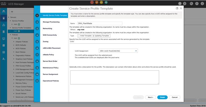
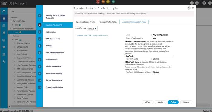
3. Select Local Disk Configuration Policy to default as Any configuration mode.
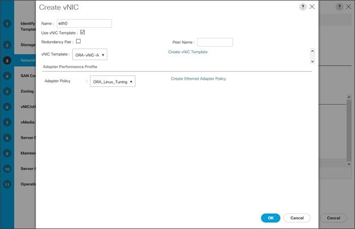
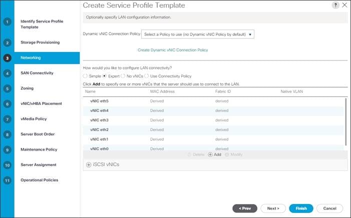
4. In the networking window, select “Expert” and click “Add” to create vNICs. Add one or more vNICs that the server should use to connect to the LAN.
5. Now there are six vNIC in the create vNIC menu. You have given name to first vNIC as “eth0” and second vNIC as “eth1.” Similarly, you have given name to third vNIC as “eth2”, fourth vNIC as “eth3.”, fifth vNIC as “eth4” and sixth vNIC as “eth5”.
6. As shown below, select vNIC Template as Oracle-vNIC-A and Adapter Policy as ORA_Linux_Tuning which was created earlier for vNIC “eth0”.
7. Similarly, as shown below, select vNIC Template as Oracle-vNIC-B and Adapter Policy as ORA_Linux_Tuning for vNIC “eth1”.

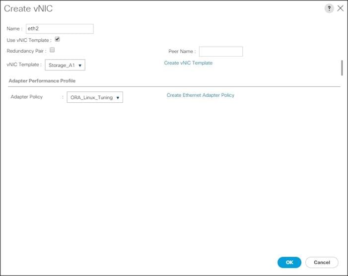
8. For vNIC “eth2”, select vNIC Template as Storage_A1 and Adapter Policy as ORA_Linux_Tuning as shown below.
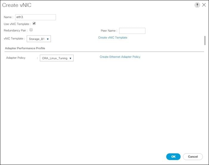
9. For vNIC “eth3”, select vNIC Template as Storage_B1 and Adapter Policy as ORA_Linux_Tuning as shown below.
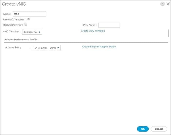
10. For vNIC “eth4”, select vNIC Template as Storage_A2 and Adapter Policy as ORA_Linux_Tuning as shown below.
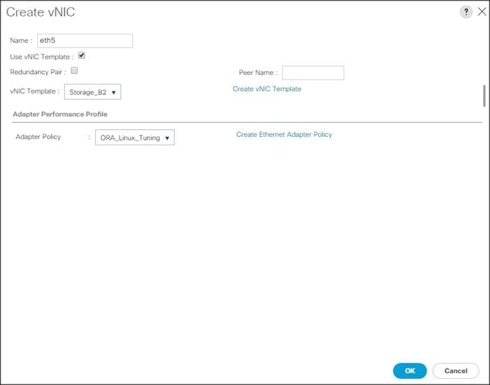
11. For vNIC “eth5”, select vNIC Template as Storage_B2 and Adapter Policy as ORA_Linux_Tuning as shown below.
![]() As shown above, eth0, eth1, eth2, eth3, eth4 and eth5 vNICs are created so that Servers can connect to the LAN and NFS Storage.
As shown above, eth0, eth1, eth2, eth3, eth4 and eth5 vNICs are created so that Servers can connect to the LAN and NFS Storage.
12. When the vNICs are created, click Next.
13. In the SAN Connectivity menu, select “No vHBAs”. Click Next.
![]() Skip zoning; for this Oracle RAC Configuration, we did not use any zoning for SAN.
Skip zoning; for this Oracle RAC Configuration, we did not use any zoning for SAN.
14. In the vNIC/vHBA Placement Menu, select option “Specify Manually”. Click vCon1 from Name option and eth0 from vNICs, and then select assign button to send “eth0” under vCon1 option. Similarly, click “eth2”, “eth4”, and select assign button to send them under vCon1 options as shown below.
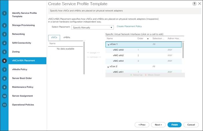
15. Similarly, click vCon2 from Name option and eth1 from vNICs, and then select assign button to send “eth1” under vCon2 option. Similarly, click “eth3”, “eth5”, and select assign button to send them under vCon2 options as shown above.
16. Keep default value in the vMedia Policy menu then click Next.
17. For the Server Boot Policy, select “Local Disk” as Boot Policy you created earlier.
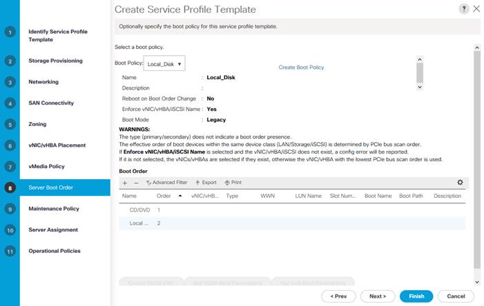
![]() The remaining maintenance and server assignment policies were left as default in the configuration. However, they may vary from site-to-site depending on workloads, best practices, and policies.
The remaining maintenance and server assignment policies were left as default in the configuration. However, they may vary from site-to-site depending on workloads, best practices, and policies.
18. Click Next and Select BIOS Policy as “OLTP_BIOS” in the BIOS Configuration.
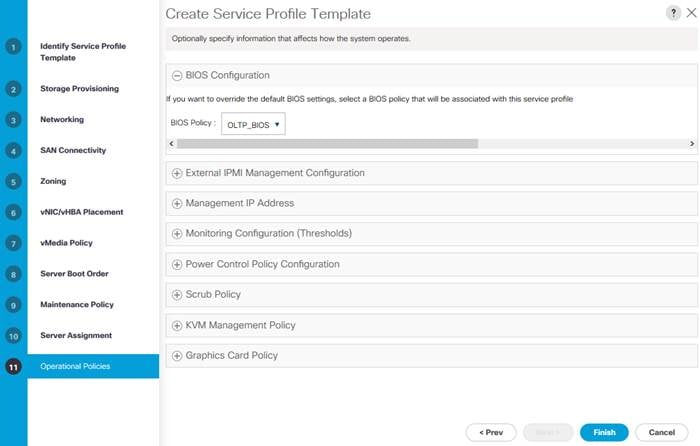
19. Click Finish to create service profile template as “ORA_FlashBlade”. This service profile template is used to create all eight service profiles for oracle RAC node 1 to 8.
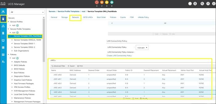
You have now created Service profile template as “ORA_FlashBlade” with each having six vNICs as shown below.
Create Service Profiles from Template and Associate to Servers
Create Service Profiles from Template
You will create eight Service profiles for eight Oracle RAC nodes as explained in the following sections.
To create first four Service Profiles from Template, complete the following steps:
1. Go to tab Servers > Service Profiles > root > and right-click “Create Service Profiles from Template.”
2. Select the Service profile template as “ORA_FlashBlade” which you created earlier and name the service profile as “ORA.”
3. To create eight service profiles, enter “Number of Instances” as 8 as shown below. This process will create service profiles as “ORA1”, “ORA2”, “ORA3”, “ORA4”, “ORA5”, “ORA6”, “ORA7” and “ORA8.”
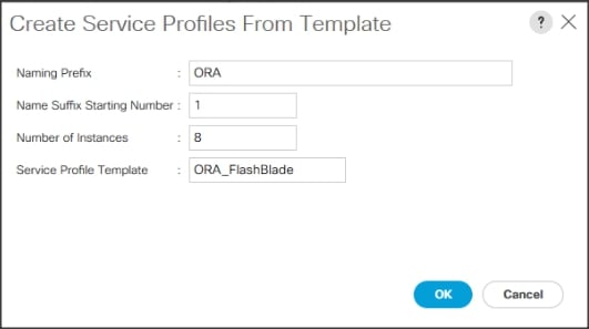
![]() When the service profiles are created, associate them to the servers as described in the following section.
When the service profiles are created, associate them to the servers as described in the following section.
Associate Service Profiles to the Servers
To associate service profiles to the servers, complete the following steps.
4. Under the Servers tab, select the desired service profile, and select Change Service Profile Association.
5. Right-click the name of service profile you want to associate with the server and select the option "Change Service Profile Association."
6. In the Change Service Profile Association page, from the Server Assignment drop-down list, select existing server that you would like to assign and click OK.
7. You will assign service profiles ORA1 to ORA4 to Chassis 1 Servers and ORA5 to ORA8 to Chassis 2 Servers.
8. Repeat the same steps to associate remaining seven service profiles for the blade servers.
You have assigned “ORA1” to Chassis 1 Server 1, Service Profile “ORA2” to Chassis 1 Server 2, Service Profile “ORA3” to Chassis 1 Server 3 and, Service Profile “ORA4” to Chassis 1 Server 4.
You have assigned Service Profile “ORA5” to Chassis 2 Server 1, Service Profile “ORA6” to Chassis 2 Server 2, Service Profile “ORA7” to Chassis 2 Server 3 and Service Profile “ORA8” to Chassis 2 Server 4.
9. Make sure all the service profiles are associated as shown below:
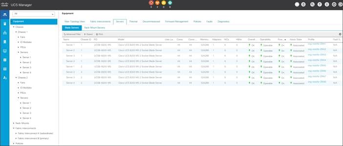
10. As shown above, make sure all the server nodes has no major or critical fault and all are in operable state.
This completes the configuration required for Cisco UCS Manager Setup.
Configure Cisco Nexus 9372PX-E Switches
The following sections details the steps for the Nexus 9372PX-E switch configuration. The details of “show run” output is listed in the Appendix.
Configure Global Settings for Cisco Nexus A and Cisco Nexus B
To set global configuration, complete the following steps on both the Nexus switches:
1. Log in as admin user into the Nexus Switch A and run the following commands to set global configurations and jumbo frames in QoS:
conf terminal
feature lacp
feature hsrp
feature vpc
feature interface-vlan
spanning-tree port type network default
spanning-tree port type edge bpduguard default
policy-map type network-qos jumbo
class type network-qos class-default
mtu 9216
exit
system qos
service-policy type network-qos jumbo
exit
copy run start
2. Log in as admin user into the Nexus Switch B and run the same above commands to set global configurations and jumbo frames in QoS.
Configure VLANs for Cisco Nexus A and Cisco Nexus B Switches
To create the necessary virtual local area networks (VLANs), complete the following steps on both Nexus switches:
1. Log in as admin user into the Nexus Switch A.
2. Create VLAN 134 for Public Network Traffic:
ORA134-NEXUS-A# config terminal
ORA134-NEXUS-A(config)# VLAN 134
ORA134-NEXUS-A(config-VLAN)# name Oracle_RAC_Public_Traffic
ORA134-NEXUS-A(config-VLAN)# no shutdown
ORA134-NEXUS-A(config-VLAN)# exit
ORA134-NEXUS-A(config)# copy running-config startup-config
ORA134-NEXUS-A(config)# exit
3. Create VLAN 10 for Private Network Traffic:
ORA134-NEXUS-A# config terminal
ORA134-NEXUS-A(config)# VLAN 10
ORA134-NEXUS-A(config-VLAN)# name Oracle_RAC_Private_Traffic
ORA134-NEXUS-A(config-VLAN)# no shutdown
ORA134-NEXUS-A(config-VLAN)# exit
ORA134-NEXUS-A(config)# copy running-config startup-config
ORA134-NEXUS-A(config)# exit
4. Create VLAN 21 for Storage Network Traffic:
ORA134-NEXUS-A# config terminal
ORA134-NEXUS-A(config)# VLAN 21
ORA134-NEXUS-A(config-VLAN)# name Storage_Traffic_A1
ORA134-NEXUS-A(config-VLAN)# no shutdown
ORA134-NEXUS-A(config-VLAN)# exit
ORA134-NEXUS-A(config)# copy running-config startup-config
ORA134-NEXUS-A(config)# exit
5. Create VLAN 22 for Storage Network Traffic:
ORA134-NEXUS-A# config terminal
ORA134-NEXUS-A(config)# VLAN 22
ORA134-NEXUS-A(config-VLAN)# name Storage_Traffic_B1
ORA134-NEXUS-A(config-VLAN)# no shutdown
ORA134-NEXUS-A(config-VLAN)# exit
ORA134-NEXUS-A(config)# copy running-config startup-config
ORA134-NEXUS-A(config)# exit
6. Create VLAN 23 for Storage Network Traffic:
ORA134-NEXUS-A# config terminal
ORA134-NEXUS-A(config)# VLAN 23
ORA134-NEXUS-A(config-VLAN)# name Storage_Traffic_A2
ORA134-NEXUS-A(config-VLAN)# no shutdown
ORA134-NEXUS-A(config-VLAN)# exit
ORA134-NEXUS-A(config)# copy running-config startup-config
ORA134-NEXUS-A(config)# exit
7. Create VLAN 24 for Storage Network Traffic:
ORA134-NEXUS-A# config terminal
ORA134-NEXUS-A(config)# VLAN 24
ORA134-NEXUS-A(config-VLAN)# name Storage_Traffic_B2
ORA134-NEXUS-A(config-VLAN)# no shutdown
ORA134-NEXUS-A(config-VLAN)# exit
ORA134-NEXUS-A(config)# copy running-config startup-config
ORA134-NEXUS-A(config)# exit
8. Log in as admin user into the Nexus Switch B and create VLAN 134 for Public Network Traffic, VLAN 10 for Private Network Traffic and VLAN 21 to 24 for Storage Network Traffic.
Virtual Port Channel (vPC) Summary for Data and Storage Network
In the Cisco Nexus 9372PX-E switch topology, a single vPC feature is enabled to provide HA, faster convergence in the event of a failure, and greater throughput. Cisco Nexus 9372PX-E vPC configurations with the vPC domains and corresponding vPC names and IDs for Oracle Database Servers is listed in Table 6.
| vPC Domain | vPC Name | vPC ID |
| 1 | Peer-Link | 1 |
| 1 | vPC Public | 51 |
| 1 | vPC Private | 52 |
As listed in Table 6, a single vPC domain with Domain ID 1 is created across two Cisco Nexus 9372PX-E member switches to define vPC members to carry specific VLAN network traffic. In this topology, we defined a total number of 3 vPCs.
vPC ID 1 is defined as Peer link communication between two Nexus switches in Fabric A and B.
vPC IDs 51 and 52 are defined for public, private and storage network traffic from Cisco UCS fabric interconnects.
Create vPC Peer-Link between the Two Nexus Switches
To create the vPC Peer-Link, complete the following steps:
Figure 7Nexus Switch Peer-Link
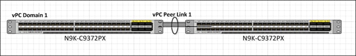
1. Log in as “admin” user into the Nexus Switch A.
![]() For vPC 1 as Peer-link, we used interfaces 1-2 for Peer-Link. You may choose the appropriate number of ports for your needs.
For vPC 1 as Peer-link, we used interfaces 1-2 for Peer-Link. You may choose the appropriate number of ports for your needs.
2. To create the necessary port channels between devices, complete the following on both the Nexus Switches:
ORA134-NEXUS-A# config terminal
ORA134-NEXUS-A(config)#feature interface-vlan
ORA134-NEXUS-A(config)#feature vpc
ORA134-NEXUS-A(config)#feature lacp
ORA134-NEXUS-A(config)#vpc domain 1
ORA134-NEXUS-A(config-vpc-domain)# peer-keepalive destination 10.29.134.6 source 10.29.134.5
ORA134-NEXUS-A(config-vpc-domain)# exit
ORA134-NEXUS-A(config)# interface port-channel 1
ORA134-NEXUS-A(config-if)# description VPC peer-link
ORA134-NEXUS-A(config-if)# switchport mode trunk
ORA134-NEXUS-A(config-if)# switchport trunk allowed VLAN 1,10,21-24,134
ORA134-NEXUS-A(config-if)# spanning-tree port type network
ORA134-NEXUS-A(config-if)# vpc peer-link
ORA134-NEXUS-A(config-if)# no shutdown
ORA134-NEXUS-A(config-if)# exit
ORA134-NEXUS-A(config)# interface Ethernet1/1
ORA134-NEXUS-A(config-if)# description Peer link connected to N9KB-Eth1/1
ORA134-NEXUS-A(config-if)# switchport mode trunk
ORA134-NEXUS-A(config-if)# switchport trunk allowed VLAN 1,10,21-24,134
ORA134-NEXUS-A(config-if)# channel-group 1 mode active
ORA134-NEXUS-A(config-if)# no shutdown
ORA134-NEXUS-A(config-if)# exit
ORA134-NEXUS-A(config)# interface Ethernet1/2
ORA134-NEXUS-A(config-if)# description Peer link connected to N9KB-Eth1/2
ORA134-NEXUS-A(config-if)# switchport mode trunk
ORA134-NEXUS-A(config-if)# switchport trunk allowed VLAN 1,10,21-24,134
ORA134-NEXUS-A(config-if)# channel-group 1 mode active
ORA134-NEXUS-A(config-if)# no shutdown
ORA134-NEXUS-A(config-if)# exit
ORA134-NEXUS-A(config)# interface Ethernet1/3
ORA134-NEXUS-A(config-if)# description Peer link connected to N9KB-Eth1/3
ORA134-NEXUS-A(config-if)# switchport mode trunk
ORA134-NEXUS-A(config-if)# switchport trunk allowed VLAN 1,10,21-24,134
ORA134-NEXUS-A(config-if)# channel-group 1 mode active
ORA134-NEXUS-A(config-if)# no shutdown
ORA134-NEXUS-A(config-if)# exit
ORA134-NEXUS-A(config)# interface Ethernet1/4
ORA134-NEXUS-A(config-if)# description Peer link connected to N9KB-Eth1/4
ORA134-NEXUS-A(config-if)# switchport mode trunk
ORA134-NEXUS-A(config-if)# switchport trunk allowed VLAN 1,10,21-24,134
ORA134-NEXUS-A(config-if)# channel-group 1 mode active
ORA134-NEXUS-A(config-if)# no shutdown
ORA134-NEXUS-A(config-if)# exit
ORA134-NEXUS-A(config)# interface Ethernet1/15
ORA134-NEXUS-A(config-if)# description connect to uplink switch
ORA134-NEXUS-A(config-if)# switchport access vlan 134
ORA134-NEXUS-A(config-if)# speed 1000
ORA134-NEXUS-A(config-if)# no shutdown
ORA134-NEXUS-A(config-if)# exit
ORA134-NEXUS-A(config)# copy running-config startup-config
3. Login as admin user into the Nexus Switch B and repeat the above steps to configure second nexus switch. (Note: Make sure to change peer-keepalive destination and source IP address appropriately for Nexus Switch B)
Create vPC Configuration between Nexus 9372PX-E and Fabric Interconnects
To create and configure vPC 51 and 52 for Data network between Nexus switches and Fabric Interconnects, complete the following steps:
Figure 8vPC Configuration Between Nexus Switches and Fabric Interconnects
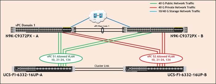
Table 7 lists the vPC IDs, allowed VLAN IDs, and Ethernet uplink ports.
| vPC Description | vPC ID | Fabric Interconnects Ports | Nexus Ports | Allowed VLANs |
|
Port Channel FI-A |
51 | FI-A Port 1/31 | N9K-A Port 2/1 |
134,10, 21 - 24
Note: VLAN 10, 22, 24 needed for failover |
| FI-A Port 1/32 | N9K-A Port 2/2 | |||
| FI-A Port 1/33 | N9K-B Port 2/1 | |||
| FI-A Port 1/34 | N9K-B Port 2/2 | |||
|
Port-Channel FI-B |
52 | FI-B Port 1/31 | N9K-A Port 2/3 |
10,134
Note: VLAN 134,10, 21-24 needed for failover |
| FI-B Port 1/32 | N9K-A Port 2/4 | |||
| FI-B Port 1/33 | N9K-B Port 2/3 | |||
| FI-B Port 1/34 | N9K-B Port 2/4 |
To create the necessary port channels between devices, complete the following steps on both Nexus Switches:
1. Log in as admin user into Nexus Switch A and perform the following:
ORA134-NEXUS-A# config Terminal
ORA134-NEXUS-A(config)# interface port-channel51
ORA134-NEXUS-A(config-if)# description connect to Fabric Interconnect A
ORA134-NEXUS-A(config-if)# switchport mode trunk
ORA134-NEXUS-A(config-if)# switchport trunk allowed vlan 1,10,21-24,134
ORA134-NEXUS-A(config-if)# spanning-tree port type edge trunk
ORA134-NEXUS-A(config-if)# mtu 9216
ORA134-NEXUS-A(config-if)# vpc 51
ORA134-NEXUS-A(config-if)# no shutdown
ORA134-NEXUS-A(config-if)# exit
ORA134-NEXUS-A(config)# interface port-channel52
ORA134-NEXUS-A(config-if)# description connect to Fabric Interconnect B
ORA134-NEXUS-A(config-if)# switchport mode trunk
ORA134-NEXUS-A(config-if)# switchport trunk allowed vlan 1,10,21-24,134
ORA134-NEXUS-A(config-if)# spanning-tree port type edge trunk
ORA134-NEXUS-A(config-if)# mtu 9216
ORA134-NEXUS-A(config-if)# vpc 52
ORA134-NEXUS-A(config-if)# no shutdown
ORA134-NEXUS-A(config-if)# exit
ORA134-NEXUS-A(config)# interface Ethernet2/1
ORA134-NEXUS-A(config-if)# description Fabric-Interconnect-A-31
ORA134-NEXUS-A(config-if)# switch mode trunk
ORA134-NEXUS-A(config-if)# switchport trunk allowed vlan 1,10,21-24,134
ORA134-NEXUS-A(config-if)# spanning-tree port type edge trunk
ORA134-NEXUS-A(config-if)# mtu 9216
ORA134-NEXUS-A(config-if)# channel-group 51 mode active
ORA134-NEXUS-A(config-if)# no shutdown
ORA134-NEXUS-A(config-if)# exit
ORA134-NEXUS-A(config)# interface Ethernet2/2
ORA134-NEXUS-A(config-if)# description Fabric-Interconnect-A-32
ORA134-NEXUS-A(config-if)# switch mode trunk
ORA134-NEXUS-A(config-if)# switchport trunk allowed vlan 1,10,21-24,134
ORA134-NEXUS-A(config-if)# spanning-tree port type edge trunk
ORA134-NEXUS-A(config-if)# mtu 9216
ORA134-NEXUS-A(config-if)# channel-group 51 mode active
ORA134-NEXUS-A(config-if)# no shutdown
ORA134-NEXUS-A(config-if)# exit
ORA134-NEXUS-A(config)# interface Ethernet2/3
ORA134-NEXUS-A(config-if)# description Fabric-Interconnect-B-31
ORA134-NEXUS-A(config-if)# switch mode trunk
ORA134-NEXUS-A(config-if)# switchport trunk allowed vlan 1,10,21-24,134
ORA134-NEXUS-A(config-if)# spanning-tree port type edge trunk
ORA134-NEXUS-A(config-if)# mtu 9216
ORA134-NEXUS-A(config-if)# channel-group 52 mode active
ORA134-NEXUS-A(config-if)# no shutdown
ORA134-NEXUS-A(config-if)# exit
ORA134-NEXUS-A(config)# interface Ethernet2/4
ORA134-NEXUS-A(config-if)# description Fabric-Interconnect-B-32
ORA134-NEXUS-A(config-if)# switch mode trunk
ORA134-NEXUS-A(config-if)# switchport trunk allowed vlan 1,10,21-24,134
ORA134-NEXUS-A(config-if)# spanning-tree port type edge trunk
ORA134-NEXUS-A(config-if)# mtu 9216
ORA134-NEXUS-A(config-if)# channel-group 52 mode active
ORA134-NEXUS-A(config-if)# no shutdown
ORA134-NEXUS-A(config-if)# exit
ORA134-NEXUS-A(config)# copy running-config startup-config
2. Log in as admin user into the Nexus Switch B and complete the following for the second switch configuration:
ORA134-NEXUS-B# config Terminal
ORA134-NEXUS-B(config)# interface port-channel51
ORA134-NEXUS-B(config-if)# description connect to Fabric Interconnect A
ORA134-NEXUS-B(config-if)# switchport mode trunk
ORA134-NEXUS-B(config-if)# switchport trunk allowed vlan 1,10,21-24,134
ORA134-NEXUS-B(config-if)# spanning-tree port type edge trunk
ORA134-NEXUS-B(config-if)# mtu 9216
ORA134-NEXUS-B(config-if)# vpc 51
ORA134-NEXUS-B(config-if)# no shutdown
ORA134-NEXUS-B(config-if)# exit
ORA134-NEXUS-B(config)# interface port-channel52
ORA134-NEXUS-B(config-if)# description connect to Fabric Interconnect B
ORA134-NEXUS-B(config-if)# switchport mode trunk
ORA134-NEXUS-B(config-if)# switchport trunk allowed vlan 1,10,21-24,134
ORA134-NEXUS-B(config-if)# spanning-tree port type edge trunk
ORA134-NEXUS-B(config-if)# mtu 9216
ORA134-NEXUS-B(config-if)# vpc 52
ORA134-NEXUS-B(config-if)# no shutdown
ORA134-NEXUS-B(config-if)# exit
ORA134-NEXUS-B(config)# interface Ethernet2/1
ORA134-NEXUS-B(config-if)# description Fabric-Interconnect-A-33
ORA134-NEXUS-B(config-if)# switch mode trunk
ORA134-NEXUS-B(config-if)# switchport trunk allowed vlan 1,10,21-24,134
ORA134-NEXUS-B(config-if)# spanning-tree port type edge trunk
ORA134-NEXUS-B(config-if)# mtu 9216
ORA134-NEXUS-B(config-if)# channel-group 51 mode active
ORA134-NEXUS-B(config-if)# no shutdown
ORA134-NEXUS-B(config-if)# exit
ORA134-NEXUS-B(config)# interface Ethernet2/2
ORA134-NEXUS-B(config-if)# description Fabric-Interconnect-A-34
ORA134-NEXUS-B(config-if)# switch mode trunk
ORA134-NEXUS-B(config-if)# switchport trunk allowed vlan 1,10,21-24,134
ORA134-NEXUS-B(config-if)# spanning-tree port type edge trunk
ORA134-NEXUS-B(config-if)# mtu 9216
ORA134-NEXUS-B(config-if)# channel-group 51 mode active
ORA134-NEXUS-B(config-if)# no shutdown
ORA134-NEXUS-B(config-if)# exit
ORA134-NEXUS-B(config)# interface Ethernet2/3
ORA134-NEXUS-B(config-if)# description Fabric-Interconnect-B-33
ORA134-NEXUS-B(config-if)# switch mode trunk
ORA134-NEXUS-B(config-if)# switchport trunk allowed vlan 1,10,21-24,134
ORA134-NEXUS-B(config-if)# spanning-tree port type edge trunk
ORA134-NEXUS-B(config-if)# mtu 9216
ORA134-NEXUS-B(config-if)# channel-group 52 mode active
ORA134-NEXUS-B(config-if)# no shutdown
ORA134-NEXUS-B(config-if)# exit
ORA134-NEXUS-B(config)# interface Ethernet2/4
ORA134-NEXUS-B(config-if)# description Fabric-Interconnect-B-34
ORA134-NEXUS-B(config-if)# switch mode trunk
ORA134-NEXUS-B(config-if)# switchport trunk allowed vlan 1,10,21-24,134
ORA134-NEXUS-B(config-if)# spanning-tree port type edge trunk
ORA134-NEXUS-B(config-if)# mtu 9216
ORA134-NEXUS-B(config-if)# channel-group 52 mode active
ORA134-NEXUS-B(config-if)# no shutdown
ORA134-NEXUS-B(config-if)# exit
ORA134-NEXUS-B(config)# copy running-config startup-config
Create vPC Configuration between Nexus 9372PX-E and Pure Storage FlashBlade
To create and configure one vPC 41 for Storage network between both Nexus switches and FlashBlade, complete the following steps:
Figure 9vPC Configuration Between Nexus Switches and FlashBlade
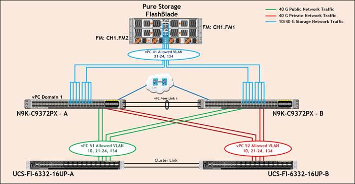
Table 8 lists the vPC IDs, allowed VLAN IDs, and Ethernet uplink ports for Nexus Switch A.
| vPC Description | vPC ID | Nexus Ports | FlashBlade Ports | Allowed VLANs |
|
Port Channel Nexus – A |
41 | N9K-A Port 1/33 | CH1.FM1.ETH1 |
VLAN 134, 21 - 24 |
| N9K-A Port 1/34 | ||||
| N9K-A Port 1/35 | ||||
| N9K-A Port 1/36 | ||||
| N9K-A Port 1/37 | CH1.FM2.ETH1 | |||
| N9K-A Port 1/38 | ||||
| N9K-A Port 1/39 | ||||
| N9K-A Port 1/40 |
Table 9 lists the vPC IDs, allowed VLAN IDs, and Ethernet uplink ports for Nexus Switch B.
| vPC Description | vPC ID | Nexus Ports | FlashBlade Ports | Allowed VLANs |
|
Port Channel Nexus – B |
41 | N9K-B Port 1/33 | CH1.FM1.ETH3 |
VLAN 134, 21 - 24 |
| N9K-B Port 1/34 | ||||
| N9K-B Port 1/35 | ||||
| N9K-B Port 1/36 | ||||
| N9K-B Port 1/37 | CH1.FM2.ETH3 | |||
| N9K-B Port 1/38 | ||||
| N9K-B Port 1/39 | ||||
| N9K-B Port 1/40 |
To create the necessary port channels between devices, complete the following steps on both Nexus Switches:
1. Log in as admin user into Nexus Switch A and perform the following:
ORA134-NEXUS-A# config Terminal
ORA134-NEXUS-A(config)# interface port-channel41
ORA134-NEXUS-A(config-if)# description Port-Channel to Storage
ORA134-NEXUS-A(config-if)# switchport mode trunk
ORA134-NEXUS-A(config-if)# switchport trunk allowed vlan 21-24,134
ORA134-NEXUS-A(config-if)# spanning-tree port type edge trunk
ORA134-NEXUS-A(config-if)# mtu 9216
ORA134-NEXUS-A(config-if)# vpc 41
ORA134-NEXUS-A(config-if)# no shutdown
ORA134-NEXUS-A(config-if)# exit
ORA134-NEXUS-A(config)# interface Ethernet1/33-36
ORA134-NEXUS-A(config-if)# description Connected to FlashBlade Controller-0
ORA134-NEXUS-A(config-if)# switch mode trunk
ORA134-NEXUS-A(config-if)# switchport trunk allowed vlan 21-24,134
ORA134-NEXUS-A(config-if)# spanning-tree port type edge trunk
ORA134-NEXUS-A(config-if)# mtu 9216
ORA134-NEXUS-A(config-if)# channel-group 41 mode active
ORA134-NEXUS-A(config-if)# no shutdown
ORA134-NEXUS-A(config-if)# exit
ORA134-NEXUS-A(config)# interface Ethernet1/37-40
ORA134-NEXUS-A(config-if)# description Connected to FlashBlade Controller-1
ORA134-NEXUS-A(config-if)# switch mode trunk
ORA134-NEXUS-A(config-if)# switchport trunk allowed vlan 21-24,134
ORA134-NEXUS-A(config-if)# spanning-tree port type edge trunk
ORA134-NEXUS-A(config-if)# mtu 9216
ORA134-NEXUS-A(config-if)# channel-group 41 mode active
ORA134-NEXUS-A(config-if)# no shutdown
ORA134-NEXUS-A(config-if)# exit
ORA134-NEXUS-A(config)# copy running-config startup-config
2. Log in as admin user into the Nexus Switch B and complete the following for the second switch configuration:
ORA134-NEXUS-B# config Terminal
ORA134-NEXUS-B(config)# interface port-channel41
ORA134-NEXUS-B(config-if)# description Port-Channel to Storage
ORA134-NEXUS-B(config-if)# switchport mode trunk
ORA134-NEXUS-B(config-if)# switchport trunk allowed vlan 21-24,134
ORA134-NEXUS-B(config-if)# spanning-tree port type edge trunk
ORA134-NEXUS-B(config-if)# mtu 9216
ORA134-NEXUS-B(config-if)# vpc 41
ORA134-NEXUS-B(config-if)# no shutdown
ORA134-NEXUS-B(config-if)# exit
ORA134-NEXUS-B(config)# interface Ethernet1/33-36
ORA134-NEXUS-B(config-if)# description Connected to FlashBlade Controller-0
ORA134-NEXUS-B(config-if)# switch mode trunk
ORA134-NEXUS-B(config-if)# switchport trunk allowed vlan 21-24,134
ORA134-NEXUS-B(config-if)# spanning-tree port type edge trunk
ORA134-NEXUS-B(config-if)# mtu 9216
ORA134-NEXUS-B(config-if)# channel-group 41 mode active
ORA134-NEXUS-B(config-if)# no shutdown
ORA134-NEXUS-B(config-if)# exit
ORA134-NEXUS-B(config)# interface Ethernet1/37-40
ORA134-NEXUS-B(config-if)# description Connected to FlashBlade Controller-1
ORA134-NEXUS-B(config-if)# switch mode trunk
ORA134-NEXUS-B(config-if)# switchport trunk allowed vlan 21-24,134
ORA134-NEXUS-B(config-if)# spanning-tree port type edge trunk
ORA134-NEXUS-B(config-if)# mtu 9216
ORA134-NEXUS-B(config-if)# channel-group 41 mode active
ORA134-NEXUS-B(config-if)# no shutdown
ORA134-NEXUS-B(config-if)# exit
ORA134-NEXUS-B(config)# copy running-config startup-config
Verify all vPC Status Is Up on Both Cisco Nexus Switches
Figure 10 Cisco Nexus Switch A Port-Channel Summary
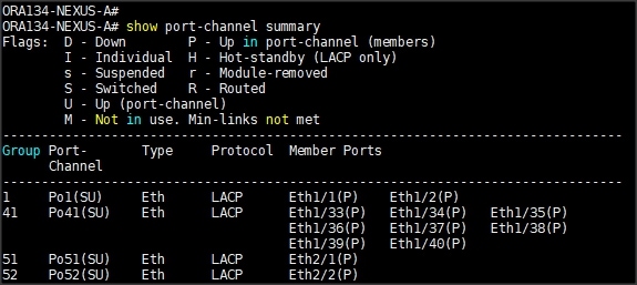
Figure 11 Cisco Nexus Switch B Port-Channel Summary
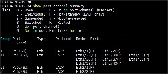
Figure 12 vPC Description for Cisco Nexus Switch A
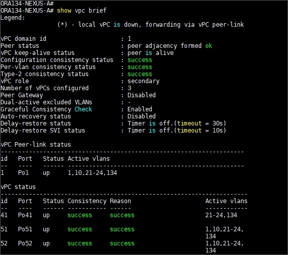
Figure 13 vPC Description for Cisco Nexus Switch B
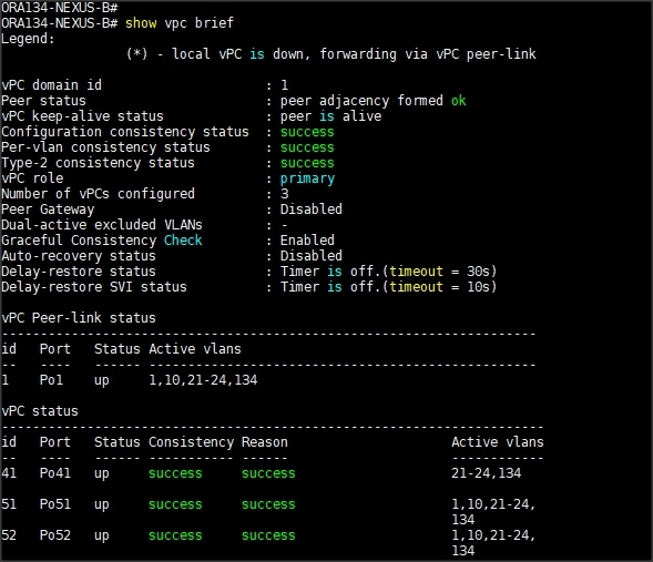
Configure Pure Storage
The design goal of the reference architecture was to best represent a real-world environment as closely as possible. The FlashStack design includes FlashBlade for increased bandwidth and throughput. There are no performance knobs to tune on FlashBlade. The hosts are redundantly connected to the controllers through 4 x 40Gb connections (2 x 40Gb per controller module) from the redundant Cisco Nexus 9K switches. FlashBlade was loaded with Purity//FB version 2.1.8, which includes a NLM (Network Lock Manager) feature for the NFS protocol to provide advisory file locking semantics.
The FlashBlade network settings were configured with five subnets across five VLANs. The NFS file systems were mounted on these four subnets on to the target host. To configure network settings into Pure Storage FlashBlade, complete the following steps:
1. Open a web browser and navigate to the Pure Storage FlashBlade Cluster address.
2. Enter the Username and Password for the storage.
3. From the Pure Storage Dashboard, go to Settings > Network. Click the “+” sign to Create Subnets.
4. Enter name, Prefix, VLAN, Gateway and MTU as shown below and click “Create” to create subnet.
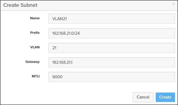
5. Click the “+” sign into the subnet VLAN21 to add Interface as shown below then click “Create” to create network interface on subnet.
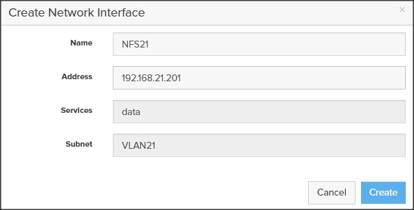
6. Add Subnets VLAN22, VLAN23 and VLAN24 and appropriate interfaces as shown below.
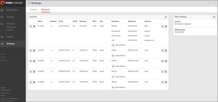
![]() For this FlashStack solution, we have configured VLAN 134 for management network traffic and four VLAN (21, 22, 23 and 24) for data network traffic. We will use these interface addresses and configure mount point on Oracle RAC nodes as discussed later in the sections.
For this FlashStack solution, we have configured VLAN 134 for management network traffic and four VLAN (21, 22, 23 and 24) for data network traffic. We will use these interface addresses and configure mount point on Oracle RAC nodes as discussed later in the sections.
Operating System Configuration
![]() Step-by-step OS installation details are not described in this document, but the following section explains the key steps for the OS installation.
Step-by-step OS installation details are not described in this document, but the following section explains the key steps for the OS installation.
1. Download Oracle Linux 7.4 OS image from https://edelivery.oracle.com/linux.
2. Launch KVM console on desired server by going to tab Equipment > Chassis > Chassis 1 > Servers > Server 1 > from right side windows General > and select KVM Console to open KVM.
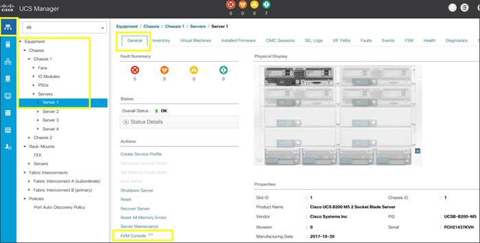
3. Click Accept security and open KVM. Enable virtual media, map the Oracle Linux ISO image and reset the server.
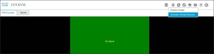
4. When the Server starts booting, it will detect the Local Disk and the virtual media connected as Oracle Linux cd.
5. It should launch the Oracle Linux installer. Select language and assign the Installation destination as local disk volume. Apply hostname and click “Configure Network” to configure all network interfaces. Alternatively, you can only configure “Public Network” in this step. You can configure additional interfaces as part of post install steps.
![]() Please verify the Device MAC Address and desired MTU settings as you configure the interfaces.
Please verify the Device MAC Address and desired MTU settings as you configure the interfaces.
6. As a part of additional RPM package, we recommend to select “Customize Now” and configure “UEK kernel Repo.”
7. After the OS install, reboot the server, complete appropriate registration steps. You can choose to synchronize the time with the NTP server. Alternatively, you can choose to use Oracle RAC cluster synchronization daemon (OCSSD). Both NTP and OCSSD are mutually exclusive and OCSSD will be setup during GRID install if NTP is not configured.
Operating System Prerequisites for Oracle Software Installation
Configure BIOS
This section describes how to optimize the BIOS settings to meet requirements for the best performance and energy efficiency for the Cisco UCS M5 generation of blade and rack servers.
Configure BIOS for Oracle Database Workloads
Oracle Database systems are often decentralized to avoid single points of failure. Spreading the work over multiple servers can also support greater transaction processing volume and reduce response time. Make sure to disable Intel IDLE driver in the OS configuration section. When Intel idle driver is disabled, the OS uses acpi_idle driver to control the c-states.
![]() For latency sensitive workloads, it is recommended to disable c-states in both OS and BIOS to ensure c-states are disabled.
For latency sensitive workloads, it is recommended to disable c-states in both OS and BIOS to ensure c-states are disabled.
The following are the recommended options for optimizing Database workloads on Cisco UCS M5 platforms managed by Cisco UCS Manager.
Figure 14 BIOS Options for Oracle Database Workloads
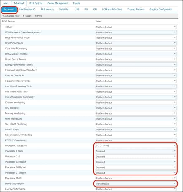
For more information about BIOS settings, refer to: https://www.cisco.com/c/dam/en/us/products/collateral/servers-unified-computing/ucs-b-series-blade-servers/whitepaper_c11-740098.pdf.
If the CPU gets into a deeper C-state and not able to get out to deliver full performance quickly. The result is unwanted latency spikes for workloads. To address this, it is recommended to disable C states in the BIOS and in addition, Oracle recommends disabling it from OS level as well by modifying grub entries. For this solution, we configured the BIOS options by modifying in /etc/default/grub file as shown below:
Prerequisites Automatic Installation
After installing Oracle Linux 7.4 on all the server nodes (ora1, ora2, ora3, ora4, ora5, ora6, ora7 and ora8), you have to configure operating system pre-requisites on all the eight nodes to successfully install Oracle RAC Database 12cR2.
![]() Follow the steps according to your environment and requirements. Refer to the Install and Upgrade Guide for Linux for Oracle Database 12c R2: https://docs.oracle.com/en/database/oracle/oracle-database/12.2/cwlin/configuring-operating-systems-for-oracle-grid-infrastructure-on-linux.html#GUID-B8649E42-4918-49EA-A608-446F864EB7A0.
Follow the steps according to your environment and requirements. Refer to the Install and Upgrade Guide for Linux for Oracle Database 12c R2: https://docs.oracle.com/en/database/oracle/oracle-database/12.2/cwlin/configuring-operating-systems-for-oracle-grid-infrastructure-on-linux.html#GUID-B8649E42-4918-49EA-A608-446F864EB7A0.
![]() You can perform either the Automatic Setup or the Manual Setup to complete the basic prerequisites. The Additional Setup is required for all installations.
You can perform either the Automatic Setup or the Manual Setup to complete the basic prerequisites. The Additional Setup is required for all installations.
To configure operating system pre-requisite for Oracle 12cR2 software on all eight nodes, complete the following steps:
For this solution, we configured the prerequisites automatically by installing the “oracle-database-server-12cR2-preinstall" rpm package. The oracle-rdbms-server-12cR2-preinstall RPM packages are accessible through the Oracle Unbreakable Linux Network (ULN, which requires a support contract), from the Oracle Linux distribution media, or from the Oracle public yum repository. You can download the required packages from http://public-yum.oracle.com/oracle-linux-7.html. If you plan to use the “oracle-database-server-12cR2-preinstall" rpm package to perform all your prerequisite setup automatically, then login as root user and issue the following command:
![]() If you have not used the "oracle-database-server-12cR2-preinstall" package, then you will have to manually perform the prerequisites tasks on all the eight nodes.
If you have not used the "oracle-database-server-12cR2-preinstall" package, then you will have to manually perform the prerequisites tasks on all the eight nodes.
Additional Prerequisites Setup
After configuring automatic or manual prerequisites steps, you have to configure a few additional steps to complete the prerequisites for the Oracle Software installations on all the eight nodes as described below.
Disable SELinux
As most of the Organizations might already be running hardware-based firewalls to protect their corporate networks, we disabled Security Enhanced Linux (SELinux) and the firewalls at the server level for this reference architecture.
You can set secure Linux to permissive by editing the "/etc/selinux/config" file, making sure the SELINUX flag is set as follows.
Disable Firewall
Check the status of the firewall by running following commands. (The status displays as active (running) or inactive (dead)). If the firewall is active / running, enter the following command to stop it:
Also, to completely disable the firewalld service, so it does not reload when you restart the host machine, run the following command:
Create the GRID User
Run the following commands to create the grid user
Set the User Passwords
Run the following commands to change the password for Oracle and Grid Users:
This process will complete all 8 Oracle RAC Nodes with OS and all prerequisites to install Oracle Database Software 12cR2.
Configure Public, Private and Storage NICs
If you have not configured network settings during OS installation, then configure it now. Each node must have at least six network interface cards (NIC), or network adapters. One adapter is for the public network interface, one adapter is for the private network interface (RAC interconnect) and four adapter are for the Storage network interfaces.
Log in as a root user and go to “/etc/sysconfig/network-scripts”. Configure Public, Private and Storage NICs with the appropriate IP addresses across all the Oracle RAC nodes.
Configure “/etc/hosts”
Log in as a root user into node and edit “/etc/hosts” file. Provide details for Public IP Address, Private IP Address, SCAN IP Address and Virtual IP Address for all nodes. Configure these settings in each Oracle RAC Nodes as shown below:
![]() You must configure the following addresses manually in your corporate setup.
You must configure the following addresses manually in your corporate setup.
· A Public IP Address for each node
· A Virtual IP address for each node
· Three single client access name (SCAN) address for the oracle cluster
![]() This completes all the required prerequisites to install Oracle Grid Infrastructure and Database 12cR2 Software. Reboot all the nodes to apply all the changes.
This completes all the required prerequisites to install Oracle Grid Infrastructure and Database 12cR2 Software. Reboot all the nodes to apply all the changes.
Configure the NFS File System on FlashBlade
To configure NFS File System on FlashBlade, complete the following steps:
1. Open a web browser and navigate to the Pure Storage FlashBlade Cluster address.
2. Enter the Username and Password for the storage.
3. From the Pure Storage Dashboard, go to Storage > File Systems. Click the “+” sign to Create File System.
4. Enter Name, Prefix, Size, Protocols NFS Enabled, Export Rules as shown below and click “Create” to create file system.
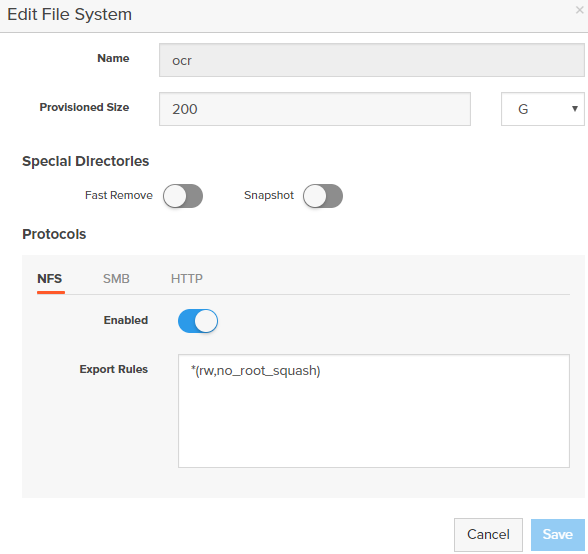
5. You will use the above created OCR File System on FlashBlade to store OCR (Oracle Cluster Registry) files, Voting Disk files, and other Clusterware files.
6. Create file systems “oradata01”, “oradata02”, “oradata03” and “oradata04” to store data files and control files as well as file system “oraredo” to store log files for the database as shown below.
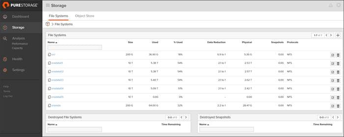
![]() More information about the File Systems for Database is explained below in the document.
More information about the File Systems for Database is explained below in the document.
Create NFS Mount Point in /etc/fstab
You have created the following local directories on each Oracle RAC nodes to mount NFS file systems:
1. Edit /etc/fstab file in each Oracle RAC node and enter the following entry to configure mount option for all the file systems.
![]() The Oracle Direct NFS (dNFS) configuration is completed at a later stage.
The Oracle Direct NFS (dNFS) configuration is completed at a later stage.
2. When you complete /etc/fstab edit, mount those file system using “mount -a” command. The following is a sample output from mount command on Node 1 (ora1)
3. Change Permission of the Mount points to Oracle User as shown below
4. These NFS file systems were mounted on all 8 nodes with similar mount names on the storage VLANs (21 – 24). Verify that all the file system volumes are mounted as shown below:
By doing this, all the oracle RAC nodes are able to read/write data from/to the file system.
When all the OS level prerequisites and file systems are configured, you are ready to install Oracle Grid Infrastructure as grid user. Download Oracle Database 12c Release 2 (12.2.0.1.0) for Linux x86-64 and Oracle Database 12c Release 2 Grid Infrastructure (12.2.0.1.0) for Linux x86-64 software from Oracle Software site. Copy these software binaries to Oracle RAC Node 1 and Unzip all files into appropriate directories.
Oracle Database 12c GRID Infrastructure Deployment
For this FlashStack solution, you will install the Oracle Grid Infrastructure and Database software binaries on all eight nodes (ora1, ora2, ora3, ora4, ora5, ora6, ora7 and ora8) on their respective local disk. Oracle 12c Release 2 Grid Infrastructure (GI) was installed on the first node as grid user. The installation also configured and added the remaining 7 nodes as part of the GI setup. ASM was configured with NFS in the Flex ASM mode.
![]() For this solution, we have placed Oracle Clusterware Binaries into local file system. Alternatively, for Oracle 12cR2, you can also use Network File System (NFS) on a certified network-attached storage (NAS) filer. Please check Oracle documentation for supported storage options for Oracle Grid Infrastructure according to your environments. https://docs.oracle.com/en/database/oracle/oracle-database/12.2/cwlin/supported-storage-options-for-oracle-grid-infrastructure.html#GUID-1022FFAD-7441-44BB-807D-C87B2DBCD015.
For this solution, we have placed Oracle Clusterware Binaries into local file system. Alternatively, for Oracle 12cR2, you can also use Network File System (NFS) on a certified network-attached storage (NAS) filer. Please check Oracle documentation for supported storage options for Oracle Grid Infrastructure according to your environments. https://docs.oracle.com/en/database/oracle/oracle-database/12.2/cwlin/supported-storage-options-for-oracle-grid-infrastructure.html#GUID-1022FFAD-7441-44BB-807D-C87B2DBCD015.
![]() It is not within the scope of this document to include the specifics of an Oracle RAC installation; you should refer to the Oracle installation documentation for specific installation instructions for your environment. We will provide a partial summary of details that might be relevant.
It is not within the scope of this document to include the specifics of an Oracle RAC installation; you should refer to the Oracle installation documentation for specific installation instructions for your environment. We will provide a partial summary of details that might be relevant.
This section describes the high-level steps for Oracle Database 12c R2 RAC install. Prior to GRID and database install, verify all the prerequisites are completed. As an alternate, you can install Oracle validated RPM that will make sure all prerequisites are meet before Oracle grid install.
For detailed information, review the Oracle Database 12c Release 2 Install and Upgrade Guide.
Configure HugePages
HugePages is a method to have larger page size that is useful for working with a very large memory. For Oracle Databases, using HugePages reduces the operating system maintenance of page states, and increases Translation Lookaside Buffer (TLB) hit ratio.
Advantages of HugePages:
· HugePages are not swappable so there is no page-in/page-out mechanism overhead.
· HugePages uses fewer pages to cover the physical address space, so the size of "book keeping"(mapping from the virtual to the physical address) decreases, so it requiring fewer entries in the TLB and so TLB hit ratio improves.
· HugePages reduces page table overhead. Also, HugePages eliminated page table lookup overhead: Since the pages are not subject to replacement, page table lookups are not required.
· Faster overall memory performance: On virtual memory systems each memory operation is actually two abstract memory operations. Since there are fewer pages to work on, the possible bottleneck on page table access is clearly avoided.
![]() For our configuration, we have used HugePages for the DSS workloads.
For our configuration, we have used HugePages for the DSS workloads.
Please refer to the Oracle Support for HugePages Configuraiton Details.
Create Directory Structure
![]() The directory structure should be create on all the RAC nodes but unzipping grid software happens on the first node only.
The directory structure should be create on all the RAC nodes but unzipping grid software happens on the first node only.
As the grid user, download the Oracle Grid Infrastructure image files and extract the files into the Grid home.
![]() You must extract the zip image software into the directory where you want your Grid home to be located. Also, Download and copy the Oracle Grid Infrastructure image files to the local node only. During installation, the software is copied and installed on all other nodes in the cluster.
You must extract the zip image software into the directory where you want your Grid home to be located. Also, Download and copy the Oracle Grid Infrastructure image files to the local node only. During installation, the software is copied and installed on all other nodes in the cluster.
Run Cluster Verification Utility
This step will verify that all prerequisites are meet to install Oracle Grid Infrastructure Software. Oracle Grid Infrastructure ships with the Cluster Verification Utility (CVU) that can run to validate pre and post installation configurations. To run this utility, login as Grid User in Oracle RAC Node 1 and go to the directory where oracle grid software binaries are located.
1. Run script named as “runcluvfy.sh” as follows:
After configuring this, you are ready to install Oracle Grid Infrastructure and Oracle Database 12c R2 standalone software. For this solution, we installed Oracle binaries on the local disk of the nodes. The OCR, Data, and redo log files reside in the file system configured on FlashBlade.
2. Log in as the grid user, and start the Oracle Grid Infrastructure installer as detailed in the next step.
Install and Configure Oracle Database Grid Infrastructure Software
![]() It is not within the scope of this document to include the specifics of an Oracle RAC installation. However, we will provide partial summary of details that might be relevant. Please refer to the Oracle installation documentation for specific installation instructions for your environment.
It is not within the scope of this document to include the specifics of an Oracle RAC installation. However, we will provide partial summary of details that might be relevant. Please refer to the Oracle installation documentation for specific installation instructions for your environment.
To install Oracle Database Grid Infrastructure Software, complete the following steps:
1. Go to grid home where the Oracle 12c R2 Grid Infrastructure software binaries are located and launch the installer as the "grid" user.
2. Start the Oracle Grid Infrastructure installer by running the following command:
./gridSetup.sh
3. Select option “Configure Oracle Grid Infrastructure for a New Cluster” as shown below, then click Next:
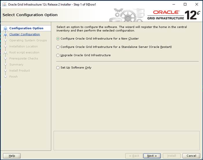
4. Select cluster configuration options “Configure an Oracle Standalone Cluster”, then click Next.
5. In next window, enter the Cluster Name and SCAN Name fields.
![]() Enter the names for your cluster and cluster scan that are unique throughout your entire enterprise network. You can select Configure GNS if you have configured your domain name server (DNS) to send to the GNS virtual IP address name resolution requests
Enter the names for your cluster and cluster scan that are unique throughout your entire enterprise network. You can select Configure GNS if you have configured your domain name server (DNS) to send to the GNS virtual IP address name resolution requests
6. In next Cluster node information window, click the "Add" button to add all eight nodes Public Hostname and Virtual Hostname as shown below:
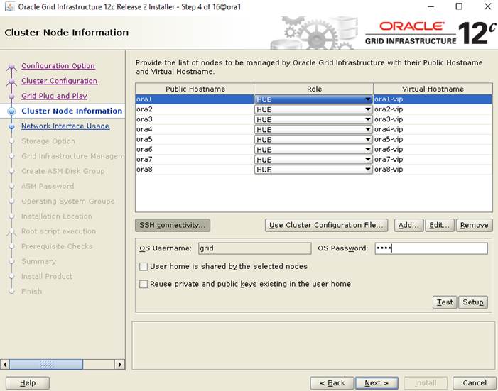
7. As shown above, you will see all nodes listed in the table of cluster nodes. Make sure the Role column is set to HUB for all eight nodes. Click the SSH Connectivity button at the bottom of the window. Enter the operating system user name and password for the Oracle software owner (grid). Click Setup.
8. A message window appears, indicating that it might take several minutes to configure SSH connectivity between the nodes. After sometime, another message window appears indicating that password-less SSH connectivity has been established between the cluster nodes. Click OK to continue.
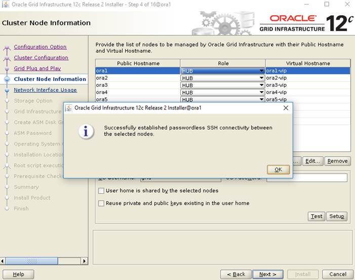
9. In Network Interface Usage screen, select the usage type for each network interface displayed as shown below:
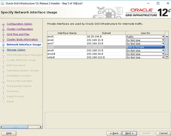
10. Select the Oracle ASM storage configuration option as “Configure ASM on NFS” as shown below then click “Next.”
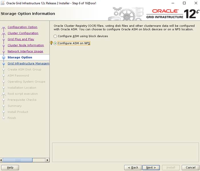
11. In the Specify the NFS Location for ASM disk groups configuration option, select the NFS mount point which we have configured earlier to store OCR and Voting disk files as shown below.
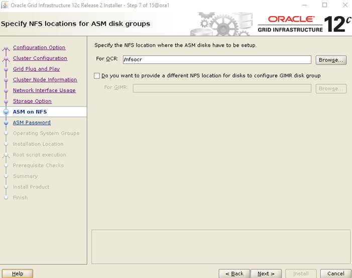
12. Choose the same password for the Oracle ASM SYS and ASMSNMP account, or specify different passwords for each account, then click Next.
13. Select the option “Do not use Intelligent Platform Management Interface (IPMI)”, then click Next.
![]() You can choose to set it up according to your requirements.
You can choose to set it up according to your requirements.
14. Select the appropriate operating system group names for Oracle ASM according to your environments.
15. Specify the directory to use for the Oracle base for the Oracle Grid Infrastructure installation and then click Next. The Oracle base directory must be different from the Oracle home directory.
![]() If you copied the Oracle Grid Infrastructure installation files into the Oracle Grid home directory as directed above, then the default location for the Oracle base directory should display as /u01/app/grid.
If you copied the Oracle Grid Infrastructure installation files into the Oracle Grid home directory as directed above, then the default location for the Oracle base directory should display as /u01/app/grid.
16. Click “Automatically run configuration scripts” to run scripts automatically during grid installation and enter the relevant root user credentials. Click Next.
17. Wait while the prerequisite checks complete. If you have any issues, use the "Fix & Check Again" button.
![]() If any of the checks have a status of Failed and are not fixable, then you must manually correct these issues. After you have fixed the issue, you can click the Check Again button to have the installer recheck the requirement and update the status. Repeat as needed until all the checks have a status of Succeeded. Click Next.
If any of the checks have a status of Failed and are not fixable, then you must manually correct these issues. After you have fixed the issue, you can click the Check Again button to have the installer recheck the requirement and update the status. Repeat as needed until all the checks have a status of Succeeded. Click Next.
18. Review the contents of the Summary window and then click Install. The installer displays a progress indicator enabling you to monitor the installation process.
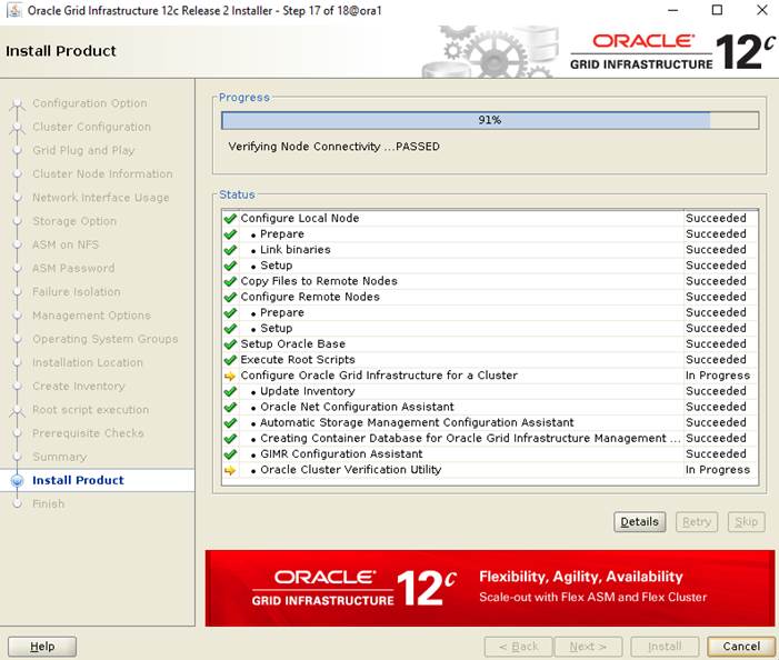
19. Wait for the grid installer configuration assistants to complete.
20. When the configuration complete successfully, click "Close" button to finish and exit the grid installer.
21. When GRID install is successful, login to each of the nodes and perform minimum health checks to make sure that Cluster state is healthy.
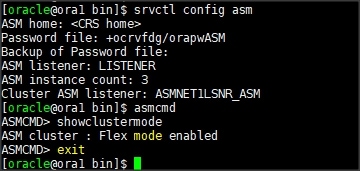
As shown in the screenshot above, ASM was installed in Flex ASM mode with an ASM instance count of 3 out of the 8-node RAC. After your Oracle Grid Infrastructure installation is complete, you can install Oracle Database on a cluster node for high availability.
Install Oracle Database Software
![]() After successful GRID install, we recommend to install Oracle Database 12c software only. You can create databases using DBCA or database creation scripts at later stage.
After successful GRID install, we recommend to install Oracle Database 12c software only. You can create databases using DBCA or database creation scripts at later stage.
![]() It is not within the scope of this document to include the specifics of an Oracle RAC database installation. However, we will provide partial summary of details that might be relevant. Please refer to the Oracle database installation documentation for specific installation instructions for your environment.
It is not within the scope of this document to include the specifics of an Oracle RAC database installation. However, we will provide partial summary of details that might be relevant. Please refer to the Oracle database installation documentation for specific installation instructions for your environment.
To install Oracle Database Software, complete the following steps as “oracle” user:
1. Start the runInstaller command from the Oracle Database 12c Release 2 (12.2) installation media where Oracle database software is located.
2. Select option “Install database software only” into Select Installation Option.
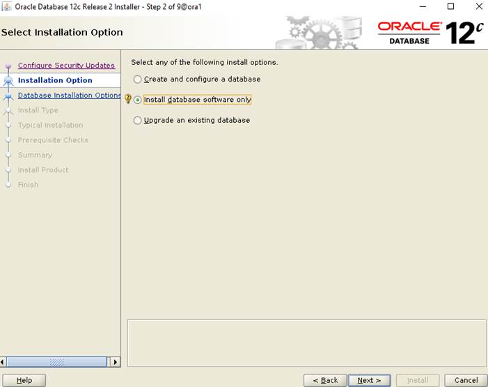
3. Select option "Oracle Real Application Clusters database installation" and click Next.
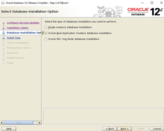
4. Select nodes in the cluster where installer should install Oracle RAC. For this setup, you will install software on all nodes as shown below.
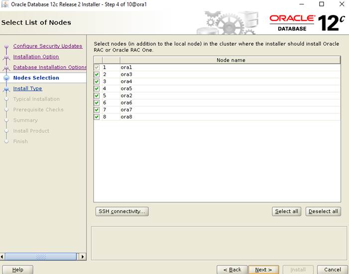
5. Click the "SSH Connectivity..." button and enter the password for the "oracle" user. Click the "Setup" button to configure passwordless SSH connectivity, and the "Test" button to test it once it is complete. When the test is complete, click Next.
6. Select Database Edition Options according to your environments and then click Next.
7. Enter Oracle Base as "/u01/app/oracle" and "/u01/app/oracle/product/12.2.0/dbhome_1" as the software location, then click Next.
8. Select the desired operating system groups and then click Next.
9. Wait for the prerequisite check to complete. If there are, any problems either click the "Fix & Check Again" button, or try to fix those by checking and manually installing required packages. Click Next.
10. Verify the Oracle Database summary information and then click Install.
11. When prompted, run the configuration script on each node as root user. When the scripts run successfully on each node, click OK.
12. Click Close to exit the installer.
Now you are ready to run synthetic IO tests against this infrastructure setup. We used fio as primary tools for IO tests.
![]() You will configure Direct NFS as you get into the actual database testing with Swingbench later in this section.
You will configure Direct NFS as you get into the actual database testing with Swingbench later in this section.
Before configuring any database for workload tests, it is extremely important to validate that it is indeed a balanced configuration capable of delivering the expected performance. FlashBlade can handle high volumes of data, leveraging massively parallel architecture, and delivers a powerful data warehouse system that is fast, big, and simple. In this FlashStack solution, we will test the scalability and high throughput performance of the FlashBlade for the Oracle Data Warehouse use cases as explained below.
Hardware Calibration Using FIO
Flexible IO (FIO), a versatile IO workload generator. FIO is a tool that will spawn a number of threads or processes doing a particular type of I/O action as specified by the user. For this solution, we used FIO to measure the performance of a storage device. We run FIO tests by changing Read/Write ratio and recorded the results over a given period.
We ran various Read/Write percentage (100/0, 90/10, 70/30, 50/50 & 0/100) combination and observed the below throughput.
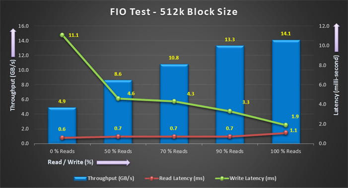
The bandwidth tests are carried out with 512K IO size and represent Data Warehouse workloads. As shown above, the bandwidth scaled linearly as we scale from 0% Read/Write to 100% Read/Write on 8 nodes. With all eight nodes, we could generate about 14.1 GB/sec of sustained bandwidth over 3 hours run period. We did not see any performance dips or degradation over the period of runtime.
Similarly, we scale 256K block size performance test from 0% Read/Write to 100% Read/Write and observed the below results.
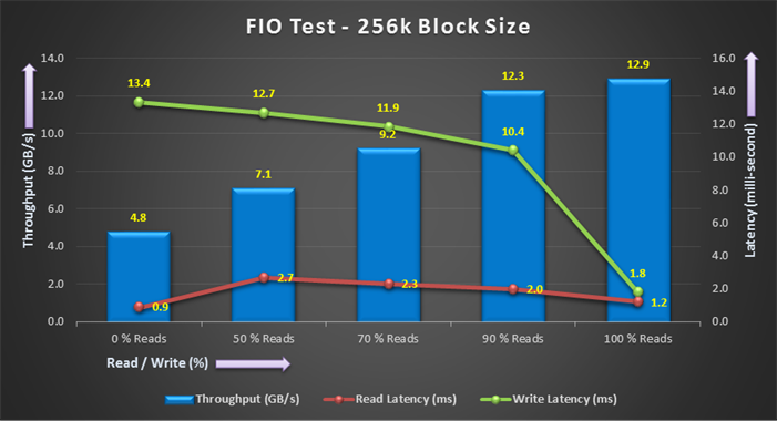
As shown above for 256K block size test, the bandwidth scaled linearly as we scale from 0% Read/Write to 100% Read/Write on 8 nodes. With all the eight nodes, we could generate about 12.9 GB/sec of sustained bandwidth over 3 hours run period. We did not see any performance dips or degradation over the period of runtime. The write latency was improving as we go from 100% write to 0% write.
Similarly, we scale 128K block size performance test from 0% Read/Write to 100% Read/Write and observed the below results.

As shown above for 128K block size test, the bandwidth scaled linearly as we scale from 0% Read/Write to 100% Read/Write on 8 nodes. With all the eight nodes, we could generate about 12.9 GB/sec of sustained bandwidth over 3 hours run period. We did not see any performance dips or degradation over the period of runtime. The write latency was improving as we go from 100% write to 0% write.
It is also important to note that this is not a benchmarking exercise and the numbers presented are not the peak numbers where there is hardware resource saturation. At this time, we are ready to create DSS database and continue with database performance tests.
Database Creation with DBCA
We used Oracle Database Configuration Assistant (DBCA) to create One DSS (Decision Support System) database to demonstrate the high-bandwidth, high throughput data warehouse type workload laid out in this solution.
The database related files (data files, redo logs, control files) were placed on FlashBlade NFS volumes as listed below. These NFS file systems were mounted on all 8 nodes with similar mount names on the storage VLANs (21 – 24) as previously explained.
Table 10 NFS Description
| Database | NFS Volume Name | Size | Description |
| DSSDB | oradata01 | 10 TB | Data and Control files for DSS Database |
| oradata02 | 10 TB | Data and Control files for DSS Database | |
| oradata03 | 10 TB | Data and Control files for DSS Database | |
| oradata04 | 10 TB | Data and Control files for DSS Database | |
| oraredo | 200 GB | Redo Log Files for DSS Database | |
| ocr | 200 GB | Oracle Cluster Registry (OCR) Files, Voting Disk Files and Other Clusterware Files |
Oracle dNFS Configuration
We recommend configuring Oracle Database to access NFS V3 servers directly using an Oracle internal Direct NFS client instead of using the operating system kernel NFS client.
To enable Oracle Database to use Direct NFS Client, the NFS file systems must be mounted and available over regular NFS mounts before you start installation. Direct NFS Client manages settings after installation. If Oracle Database cannot open an NFS server using Direct NFS Client, then Oracle Database uses the platform operating system kernel NFS client. You should still set the kernel mount options as a backup, but for normal operation, Direct NFS Client uses its own NFS client.
Direct NFS Client supports up to four network paths to the NFS server. Direct NFS Client performs load balancing across all specified paths. If a specified path fails, then Direct NFS Client reissues I/O commands over any remaining paths.
About the oranfstab File and Direct NFS Client
If you use Direct NFS Client, then you can use a new file specific for Oracle data file management, oranfstab, to specify additional options specific for Oracle Database to Direct NFS Client. For example, you can use oranfstab to specify additional paths for a mount point. You can add the oranfstab file either to /etc or to $ORACLE_HOME/dbs.
With shared Oracle homes, when the oranfstab file is placed in $ORACLE_HOME/dbs, the entries in the file are specific to a single database. In this case, all nodes running an Oracle RAC database use the same $ORACLE_HOME/dbs/oranfstab file. In non-shared Oracle RAC installs, oranfstab must be replicated on all nodes. The oranfstab configuration in $ORACLE_HOME/dbs is local to the database under $ORACLE_HOME, whereas the oranfstab in /etc/oranfstab applies to all Oracle databases on that server.
When the oranfstab file is placed in /etc, then it is globally available to all Oracle databases, and can contain mount points used by all Oracle databases running on nodes in the cluster, including standalone databases. However, on Oracle RAC systems, if the oranfstab file is placed in /etc, then you must replicate the file /etc/oranfstab file on all nodes, and keep each /etc/oranfstab file synchronized on all nodes, just as you must with the /etc/fstab file.
![]() In all cases, mount points must be mounted by the kernel NFS system, even when they are being served using Direct NFS Client. Refer to your vendor documentation to complete operating system NFS configuration and mounting. Please refer Oracle document for more information: https://docs.oracle.com/database/121/CWLIN/storage.htm#CWLIN270
In all cases, mount points must be mounted by the kernel NFS system, even when they are being served using Direct NFS Client. Refer to your vendor documentation to complete operating system NFS configuration and mounting. Please refer Oracle document for more information: https://docs.oracle.com/database/121/CWLIN/storage.htm#CWLIN270
Direct NFS Client searches for mount entries in the following order.
1. $ORACLE_HOME/dbs/oranfstab
2. /etc/oranfstab
3. /etc/mtab
![]() If a volume is not listed in oranfstab, Oracle will look through the OS mount tab (/etc/mtab) to find a match. If that fails, control is handed back to the database and file access is made through Kernel NFS.
If a volume is not listed in oranfstab, Oracle will look through the OS mount tab (/etc/mtab) to find a match. If that fails, control is handed back to the database and file access is made through Kernel NFS.
Typical syntax for the oranfstab is:
![]() Oracle dNFS was enabled at the RDBMS level on all the database nodes, and the oranfstab was updated to reflect the same across all nodes.
Oracle dNFS was enabled at the RDBMS level on all the database nodes, and the oranfstab was updated to reflect the same across all nodes.
The following is a sample oranfstab configuration from Oracle RAC Node 1:
![]() When oranfstab file is created on all nodes, you need to enable the direct NFS client ODM library on all nodes. Please shutdown the databases before this step. You can perform this as shown below:
When oranfstab file is created on all nodes, you need to enable the direct NFS client ODM library on all nodes. Please shutdown the databases before this step. You can perform this as shown below:
This completes dNFS setup.
![]() Oracle dNFS is by default enabled on Oracle 12c. To disable dNFS, the RDBMS should be rebuilt with the dnfs_off option. Please check the Best Practices section for enabling/disabling Oracle dNFS.
Oracle dNFS is by default enabled on Oracle 12c. To disable dNFS, the RDBMS should be rebuilt with the dnfs_off option. Please check the Best Practices section for enabling/disabling Oracle dNFS.
Verify if Oracle dNFS is enabled at the database level and working as expected. Run a SQL query against v$dnfs_servers that should show the details of the dNFS mounts as shown below
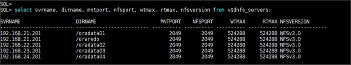
SwingBench Performance on FlashBlade
The first step after creating the databases is calibrating the concurrent users, nodes, OS and database optimization. We have used Swingbench tool to validate the data-warehouse type workload on an eight node Oracle RAC as explained below.
Database Workload Configuration
Swingbench is a simple to use, free, Java-based tool to generate database workload and perform stress testing using different benchmarks in Oracle database environments. Swingbench can be used to demonstrate and test technologies such as Real Application Clusters, Online table rebuilds, Standby databases, online backup and recovery, etc.
Swingbench provides four separate benchmarks, namely, Order Entry, Sales History, Calling Circle, and Stress Test. For the tests described in this solution, Swingbench Sales History benchmark was used for the DSS workload testing.
The Sales History benchmark is based on the SH schema and is TPC-H like. The workload is query (read) centric and is designed to test the performance of queries against large tables. The benchmark illustrates decision support systems that examine large volumes of data and execute queries with a high degree of complexity.
Swingbench SH wizard was used for the database schema creation and to load into the database data files. We have configured nearly around 8 TB of DSS database by loading Swingbench SH schema into Data Files of the Tablespace as shown below.
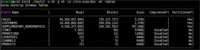
Database Performance
The data warehouse workloads are generally sequential in nature, read intensive, and exercise large IO size. DSS database workload runs a small number of users that typically exercise extremely complex queries that run for hours. Typically encountered in the real-world deployments, we tested a combination of scalability and stress related scenarios that ran on all the 8-node Oracle RAC cluster configuration for 24 hours run to validate sustained configuration.
We have captured DSS Database activity for all the eight Oracle RAC Instances using Oracle Enterprise Manager as well as Pure Storage GUI.
For this test, we ran Swingbench Sales history workload with 64 users. The charts below show DSS workload results captured from Oracle Enterprise Manager for the 24-hour workload test.
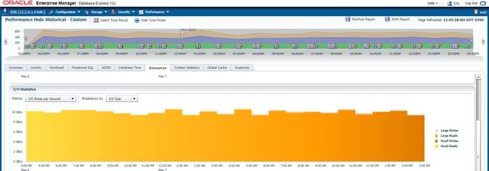
As shown above, for 24 hours DSS workload test, we observed the total IO bandwidth ranging between 10.2 GB/s to 10.8 GB/s.
The below screenshot shows Pure Storage FlashBlade GUI for the same 24 hour DSS workload Test. We also observed Read and Write Latency was under 20 milliseconds throughout the test run.
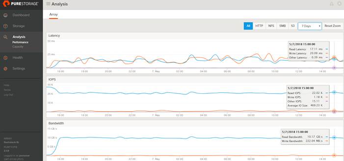
As indicated on the chart below, the I/O was evenly distributed across all the eight Oracle RAC nodes and we did not observe any significant dips in performance and IO bandwidth for a sustained period.
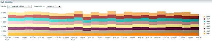
The screenshot shown below shows the CPU Utilization, Active Sessions and IO Throughput for each Oracle RAC Instance while Swingbench test was running. The servers CPU utilization averaged around 35% for the 24-hour run and we did not observe any queueing or bandwidth saturation for the Network interfaces also.
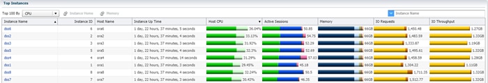
The screenshot shown below shows the System Statistics of Physical IO Bytes Per Second throughout 24-hour test run.
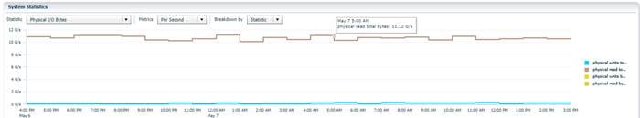
Node Scalability
This test shows the scalability aspect of this FlashStack solution and the scale-out functionality that makes it very simple to add and gain performance as needed for each physical server node.
For these tests, we ran the Swingbench workload on one, two, four, six, and eight Oracle RAC Nodes.
The screenshot shown below shows Latency and Throughput of the DSS Database during Swingbench workload test running on two Oracle RAC Nodes. We recorded average 2.92 GB/s Bandwidth during the test with read and write latency always under three milliseconds.
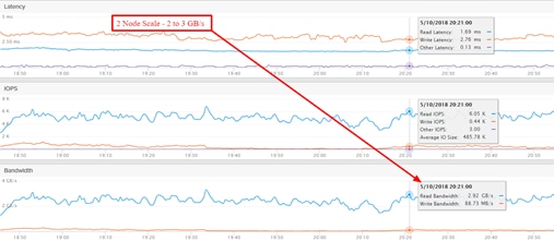
The screenshot shown below shows Latency and Throughput of the DSS Database during Swingbench workload test running on four Oracle RAC Nodes. We recorded average 6.24 GB/s Bandwidth during the test.
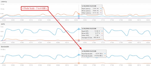
The screenshot shown below shows Latency and Throughput of the DSS Database during Swingbench workload test running on six Oracle RAC Nodes. We recorded average 8.49 GB/s Bandwidth during the test.
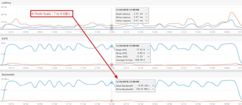
The screenshot shown below shows Latency and Throughput of the DSS Database during Swingbench workload test running on eight Oracle RAC Nodes. We recorded average 11.1 GB/s Bandwidth during the test.
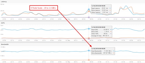
We recorded the below throughput for 1 node to 8 node Oracle RAC node Scale test.
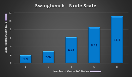
The results show a close-to-perfect linear scalability from one Oracle RAC node to eight Oracle RAC nodes. As the response time includes Oracle’s end-to-end time, the throughput numbers don’t reflect the maximum achievable throughput on FlashBlade.
Oracle also equally distributed the parallel queries across the 8 RAC nodes, which helped in extracting high performance across all the infrastructure components through which I/O passes between hosts and storage (I/O modules, Fabric Interconnects, 9K switches).
This test also validates FlashBlade’s simplicity approach to scale out and gain performance.
Data Reduction on FlashBlade
The screenshot below shows the data reduction rate we achieved for this entire performance test.
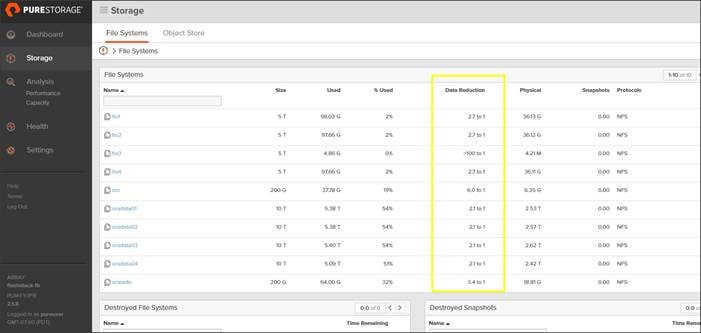
For this solution, we achieved an average 2:1 data reduction rate throughout all the time.
![]() Actual data reduction may vary based on use case.
Actual data reduction may vary based on use case.
Best Practice for Oracle Database on FlashBlade
NFS File System for Oracle
Networked file systems provide the flexibility to mount the same file system across multiple hosts, which meets the shared storage requirement for Oracle RAC. NFS file systems can certainly be used for single instances as well. Make sure the NFS protocol is selected when creating the file system on FlashBlade.
Use dNFS over Kernel NFS
To scale up bandwidth on FlashBlade, enable numerous connections from the client rather than a single connection. Oracle’s Direct NFS creates a separate connection to the storage system for every server process, as opposed to a single connection per mount point via Kernel NFS.
Enable Parallelism
To increase read and write bandwidth on FlashBlade, use client level parallelization techniques like parallel queries and multiple RMAN channels based on the CPU availability of your host in conjunction with dNFS. This increases the number of connections to FlashBlade, especially with dNFS.
Use Multiple Network Interface
To enhance network bandwidth, be sure to have multiple network interfaces on the client. These multiple interfaces can be configure on a single subnet or on multiple subnets.
Multiple Subnets
Direct NFS client best practices recommend always using multipath in separate subnets. Below is the screenshot for one of the node routing table.
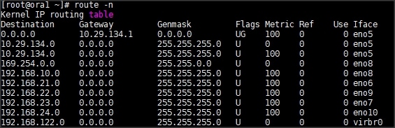
In this case, these are four storage dynamic routes and, based on the traffic, the route is selected automatically. As such, if you decide to use multiple subnets, they should be configured on both the client and the FlashBlade sides. Multiple subnets can be configured in the FlashBlade GUI under Network Settings as explained earlier in the storage configuration section.
![]() Oracle recommends using a separate subnet for each, and it supports up to four subnets. With multiple subnets, there is no need to bond the network interfaces to aggregate bandwidth across the available interfaces. The routing will be automatic in the case of multiple subnets.
Oracle recommends using a separate subnet for each, and it supports up to four subnets. With multiple subnets, there is no need to bond the network interfaces to aggregate bandwidth across the available interfaces. The routing will be automatic in the case of multiple subnets.
![]() Be sure to update the oranfstab with the subnets and the mount point details. In an RAC environment, all RAC nodes should have the appropriate oranfstab file configured.
Be sure to update the oranfstab with the subnets and the mount point details. In an RAC environment, all RAC nodes should have the appropriate oranfstab file configured.
NFS Volumes and Mount Point Requirements
It is not required to have as many NFS filesystems/volumes as subnets for dNFS to be effective. Also, it is not required to mount a single volume on to all subnets for dNFS to be effective either. Oracle dNFS reads the oranfstab and, based on the storage paths and mount details, it will create multiple paths when the database files are accessed. For example, with two subnets and two mounts, dNFS would create four paths to the storage system for every server process.
Linux Mount Options
For mounting the NFS filesystem on Linux, use the following mount options. Do not specify the rsize, wsize options as the system can get the default offered by FlashBlade, which is 524288.
Enabling and Disabling Direct NFS Client
To enable the Direct NFS Client, the standard Oracle Disk Manager (ODM) library that supports Direct NFS Client should be used. It can be enabled as follows (beginning with Oracle 11.2).
To disable the Direct NFS Client, perform the following:
Verifying the Use of Direct NFS Client
If dNFS is enabled, the alert.log will show the following entry when the database is started:
Check the dNFS server information from v$dnfs_servers view.
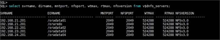
Resiliency and Failure Tests
The goal of these tests is to help ensure that the reference architecture withstands commonly occurring failures due to either unexpected crashes, hardware failures, or human errors. We conducted many hardware (disconnect power), software (process kills) and OS specific failures that simulate real world scenarios under stress condition. In the destructive testing, we also demonstrated unique failover capabilities of Cisco UCS components.
Below is the architecture diagram for this FlashStack solution under normal operating conditions.
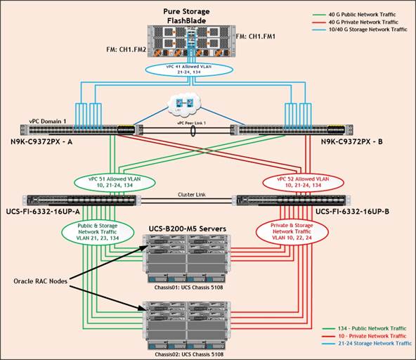
Cisco UCS 6332-16UP Fabric Interconnects carries both storage and network traffic from the blades with the help of Cisco Nexus 9372PX-E switches. Two virtual Port-Channels (vPCs) are configured to provide public network, private network and storage network paths for the blades to northbound switches. Eight (four per chassis) links go to Fabric Interconnect – A. Similarly, eight links go to Fabric Interconnect – B.
· Fabric Interconnect – A links are used for Oracle Public Network (VLAN 134) and Storage Network (VLAN 21 & 23) traffic shown as green lines.
· Fabric Interconnect – B links are used for Oracle Private Interconnect Network (VLAN 10) and Storage Network (VLAN 22 & 24) traffic shown as red lines. Storage Network Traffic from both the Nexus Switch to FlashBlade is shown as blue lines.
The screenshots below show the complete infrastructure details of VLAN and MAC address details for Cisco UCS Fabric Interconnect – A and Fabric Interconnect – B switches under normal working condition.
1. Log into Cisco Fabric Interconnect – A and “connect nxos a” then type “show mac address-table” to see all VLAN connection on Fabric Interconnect – A.
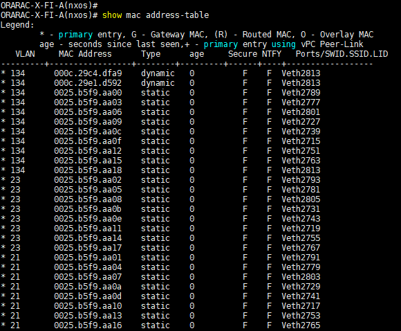
As shown in the above screenshot, Fabric Interconnect – A carry Oracle Public Network Traffic on VLAN 134 and Storage Network Traffic on VLAN 21 & 23 under normal operating conditions before failover test.
2. Log into Cisco Fabric Interconnect – B and “connect nxos b” then type “show mac address-table” to see all VLAN connection on Fabric Interconnect – B.
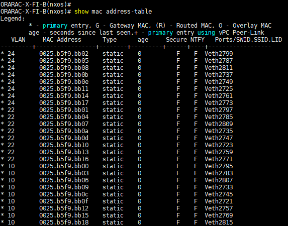
As shown in the above screenshot, Fabric Interconnect – B carry Oracle Private Network Traffic on VLAN 10 and Storage Network Traffic on VLAN 22 & 24 under normal operating conditions before failover test.
We have highlighted some of the common failure scenario in the architecture diagram as shown below. We will describe only a few test scenario performed and observe the results as explained below.
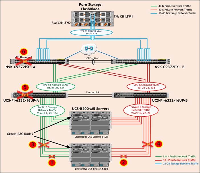
Table 11 Hardware Failover Tests
| Test | Scenario | Description | Verified Result |
| 1 | Single Link Failure (Public or Storage Interface on FI-A Side) | Disconnect any one links going to FI-A from Chassis 2 IOM by pulling it out. | No disruption in Public or Storage Interface traffic because of Port-Channel benefit. |
| 2 | Single Link Failure (Private or Storage Interface on FI-B Side) | Disconnect any one links going to FI-B from Chassis 2 IOM by pulling it out. | No disruption in Public or Storage Interface traffic because of Port-Channel benefit. |
| 3 | All Links Failure (Public or Storage Interface on FI-A Side) | Disconnect all the links going to FI-A from Chassis 2 IOM by pulling it out. | No disruption in network traffic. All nodes should continue work via failover path through another FI Switch. |
| 4 | All Links Failure (Private or Storage Interface on FI-B Side) | Disconnect all the links going to FI-B from Chassis 2 IOM by pulling it out. | |
| 5 | Any one Fabric Interconnect Failure | Power Off Fabric Interconnect – A and check the network traffic on Fabric Interconnect – B. | |
| 6 | Any one Nexus Switch Failure | Power Off Nexus Switch – A and check the network traffic on Nexus Switch – B. | No disruption in Network Interface Traffic. All nodes should continue work (vPC) |
Test Scenario 1 – Chassis IOM Single Link Failure (Public or Storage Interface on FI-A Side)
We conducted a Chassis IOM single Link Failure test by disconnecting anyone of the server port cable going to FI-A from the Chassis as shown below.
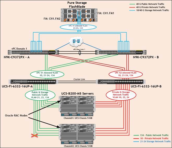
Unplug anyone of the server port cables from chassis 2 going to FI-A, then check the MAC address and VLAN traffic information on both UCS Fabric Interconnects. We noticed no disruption in public, private and storage network traffic after one chassis link failed because of the port-channel feature.
![]() We conducted Test Scenario 2 (Chassis IOM Single Link Failure on FI-B Side) and observed expected results.
We conducted Test Scenario 2 (Chassis IOM Single Link Failure on FI-B Side) and observed expected results.
Test Scenario 3 – Chassis IOM All Links Failure (Public or Storage Interface on FI-A Side)
We conducted a Chassis IOM all links failure test by disconnecting all of the server port cable going to FI-A from the Chassis as shown below.
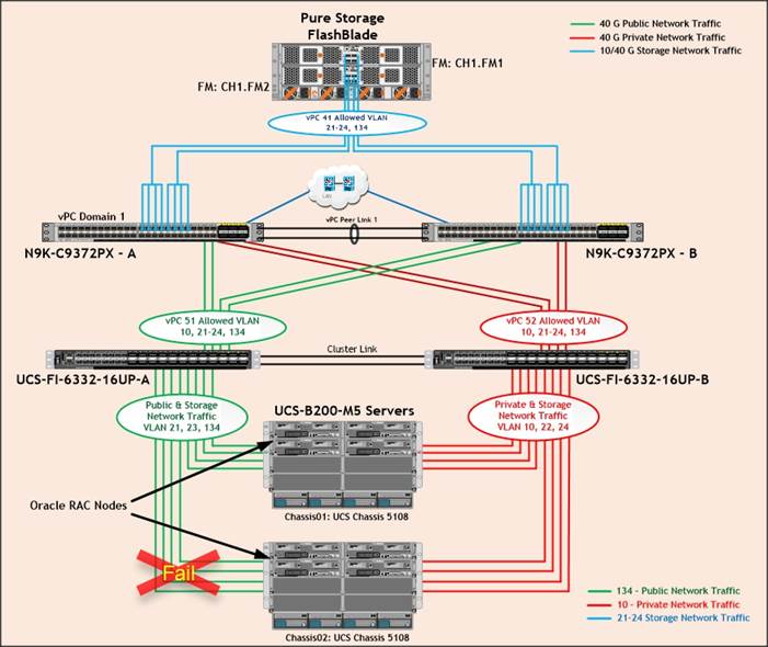
As shown above, unplug all the server port cables from chassis 2 going to FI-A, then check the MAC address and VLAN traffic information on both UCS Fabric Interconnects.
The screenshot below shows MAC Address information from FI-A.
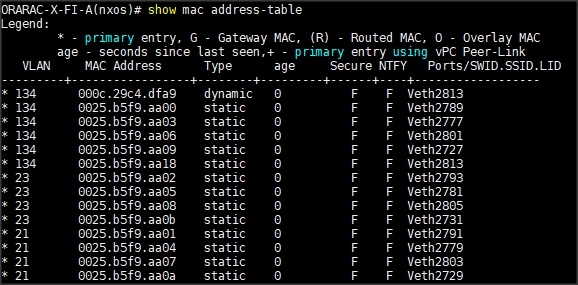
The screenshot below shows MAC Address information from FI-B.
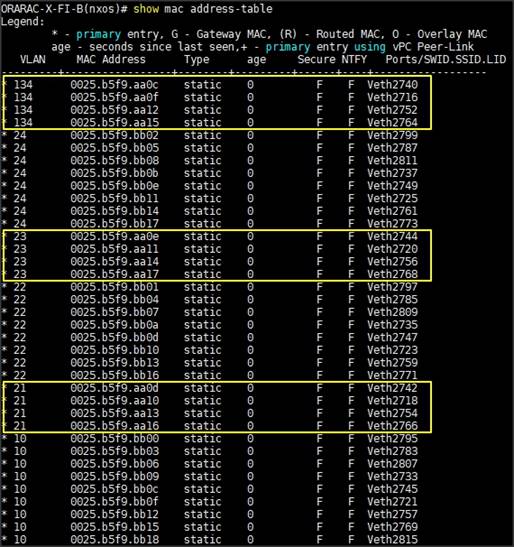
As indicated in the screenshot above, we noticed that, appropriate VLAN and MAC addresses of those chassis 2 servers (ora5, ora6, ora7 and ora8) route the network traffic to Fabric Interconnect – B. So Chassis all links failure did not cause any disruption to Public, Private and Storage Network Traffic.
After plugging in all the links of chassis, the respective servers (ora5, ora6, ora7 and ora8) on chassis 2 will route back the MAC addresses and its VLAN traffic to Fabric Interconnect – A.
![]() We conducted Test Scenario 4 (Chassis IOM All Links Failure on FI-B Side) and observed expected results.
We conducted Test Scenario 4 (Chassis IOM All Links Failure on FI-B Side) and observed expected results.
Test Scenario 5 – Cisco UCS anyone Fabric Interconnect Failure
We conducted a hardware failure test on Fabric Interconnect – A by disconnecting power cable to the switch as explained below.
The figure below illustrates how during Fabric Interconnect – A switch failure, the respective blades (ORA1, ORA2, ORA3 and ORA4) on chassis 1 and (ORA5, ORA6, ORA7 and ORA8) on chassis 2 will fail over the public and storage interface MAC addresses and its VLAN network traffic to fabric interconnect – B.
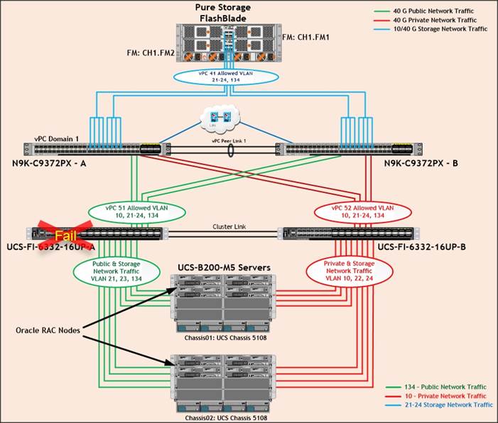
We unplugged the power cable from Fabric Interconnect – A then checked the MAC address and VLAN information on Cisco UCS Fabric Interconnect – B.
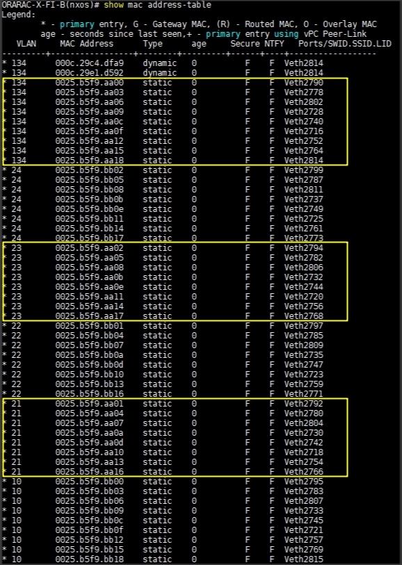
We noticed in the figure above, when the Fabric Interconnect – A failed, it would route all the Public and Storage Network traffic of VLAN 134, 21 & 23 to Fabric Interconnect – B. So Fabric Interconnect – A Failover did not cause any disruption to Private, Public and Storage Network Traffic.
After plugging in the power cable to Fabric Interconnect – A Switch, the respective blades (ORA1, ORA2, ORA3 & ORA4) on chassis 1 and (ORA5, ORA6, ORA7 & ORA8) on chassis 2 will route back the MAC addresses and its VLAN traffic to Fabric Interconnect – A.
![]() We conducted a hardware failure test on Fabric Interconnect – B by disconnecting power cable to the switch and observed the expected results. Therefore Fabric Interconnect – B Failover did not cause any disruption to Private, Public and Storage Network Traffic.
We conducted a hardware failure test on Fabric Interconnect – B by disconnecting power cable to the switch and observed the expected results. Therefore Fabric Interconnect – B Failover did not cause any disruption to Private, Public and Storage Network Traffic.
Test Scenario 6 – Cisco UCS anyone Nexus Switch Failure
We conducted a hardware failure test on Nexus Switch – A by disconnecting power cable to the switch as explained below.
The figure below illustrates how during Nexus Switch – A failure, the respective blades (ORA1, ORA2, ORA3 and ORA4) on chassis 1 and (ORA5, ORA6, ORA7 and ORA8) on chassis 2 will fail over the MAC addresses and its VLAN network traffic to Nexus Switch – B.
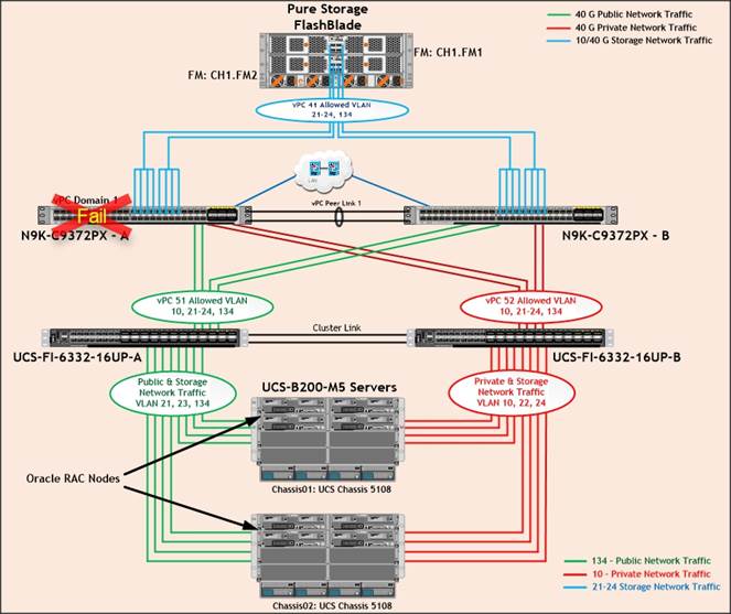
We unplugged the power cable from Nexus Switch – A, and checked the MAC address and VLAN information on Cisco UCS Nexus Switch – B. We noticed when the Nexus Switch – A failed, it would route all the Public, Private and Storage Network Traffic of VLAN 10, VLAN 134, VLAN 21 to 24 to Nexus Switch – B. Therefore, Nexus Switch – A Failover did not cause any disruption to Private, Public and Storage Network Traffic.
After plugging in the power cable to Nexus Switch – A Switch, the respective blades on chassis 1 and chassis 2 will route back the MAC addresses and its VLAN traffic to Nexus Switch – A.
![]() Similarly, we unplugged the power cable from Nexus Switch – B, and observed expected results. Thus, Nexus Switch – B Failover did not cause any disruption to Private, Public and Storage Network Traffic.
Similarly, we unplugged the power cable from Nexus Switch – B, and observed expected results. Thus, Nexus Switch – B Failover did not cause any disruption to Private, Public and Storage Network Traffic.
The screenshot shown below shows the above tests performed while database was running the workload.
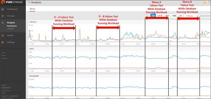
As expected during Fabric Interconnect – A failure, it would route all the appropriate traffic of VLAN Fabric Interconnect – B and database performance was persistent. Similarly, during Fabric Interconnect – B failure, it would route all the appropriate traffic of VLAN Fabric Interconnect – A and database performance was not affected. Likewise, we observed Nexus Switch failure did not cause any degradation on database performance.
From the above test, we can conclude that there are no single point of failure in this reference design. All of these failure tests were performed while database workload was running. We did not observe any significant dips in performance and IO bandwidth during the failure scenarios.
Cisco and Pure Storage have partnered to deliver the FlashStack solution that uses best-in-class storage, server, and network components to serve as the foundation for a variety of workloads, enabling efficient architectural designs that can be quickly and confidently deployed. FlashStack Datacenter is predesigned to provide agility to large enterprise data centers with high availability and storage scalability. With a FlashStack solution, customers can leverage a secure, integrated, and optimized stack that includes compute, network, and storage resources that are sized, configured, and deployed as a fully tested unit running industry standard applications such as Oracle RAC Database 12c R2.
The following factors make the combination of Cisco UCS with Pure Storage so powerful for Oracle environments:
· Cisco UCS stateless computing architecture provided by the Service Profile capability of Cisco UCS allows fast, non-disruptive workload changes to be executed simply and seamlessly across the integrated UCS infrastructure and Cisco x86 servers.
· Cisco UCS, combined with Pure Storage’s highly scalable FlashBlade Storage system provides the ideal combination for Oracle's unique, scalable, and highly available NFS technology.
· Hardware level redundancy for all major components using Cisco UCS and Pure Storage availability features.
Oracle data warehouse deployments are not easy. Ensuring performance, availability, and low TCO are always top priorities for IT managers and DBAs. In this Cisco Validated Design, we have demonstrated how to address those challenges using the right tools from Oracle running on the right infrastructure from Cisco UCS and Pure Storage. This solution enables your user community to perform ad-hoc analysis across all of the data in your Oracle data warehouse quickly, cost-effectively, and with a solution that scales out virtually on the fly.
· Excellent throughput performance, achieved across data warehouse workloads through high-end data ingest and business-related queries
· The scalability of Oracle RAC Nodes, in which throughput went from 1.5 GB/s with 1 node to 11.23 GB/s with 8 nodes.
Overall, the test results prove that a data warehouse solution on Oracle RAC is an ideal use case for FlashStack Converged Infrastructure with FlashBlade. Excellent bandwidth, high throughput, and scalability were achieved – showcasing the versatility of FlashBlade within the FlashStack CI solution. Finally, factors like service profiles via UCS, Oracle dNFS, ease of storage management, and lower costs for power, cooling, and rack space make the TCO for large scale deployments even more attractive.
The following references were used in preparing this document.
Cisco Unified Computing System
https://www.cisco.com/c/en/us/products/servers-unified-computing/index.html
Cisco UCS B200 M5 Blade Servers
Oracle Database 12c Release 2
https://docs.oracle.com/en/database/oracle/oracle-database/12.2/index.html
Pure Storage FlashBlade
https://www.purestorage.com/products/flashblade.html
Pure Storage Support Pages
https://support.purestorage.com/
Cisco UCS Manager
https://www.cisco.com/c/en/us/products/servers-unified-computing/ucs-manager/index.html
Cisco UCS Solutions for Data Center Applications
Cisco Nexus 9372PX-E Running Configuration
ORA134-NEXUS-A# show running-config
!Command: show running-config
!Time: Sat Jun 2 01:21:04 2018
version 7.0(3)I4(8)
switchname ORA134-NEXUS-A
policy-map type network-qos jumbo
class type network-qos class-default
mtu 9216
vdc ORA134-NEXUS-A id 1
limit-resource vlan minimum 16 maximum 4094
limit-resource vrf minimum 2 maximum 4096
limit-resource port-channel minimum 0 maximum 511
limit-resource u4route-mem minimum 248 maximum 248
limit-resource u6route-mem minimum 96 maximum 96
limit-resource m4route-mem minimum 58 maximum 58
limit-resource m6route-mem minimum 8 maximum 8
cfs eth distribute
feature interface-vlan
feature hsrp
feature lacp
feature vpc
no password strength-check
username admin password 5 $5$RVD7EXgX$j8C3VaP4dox9.ncFILksvy/Ypiivvm4.X1WVg/JZNYA role network-admin
ip domain-lookup
system qos
service-policy type network-qos jumbo
copp profile strict
snmp-server user admin network-admin auth md5 0x245a78523ec9113d79755d724da371c1 priv 0x245a78523ec9113d79755d724da371c1 localizedkey
rmon event 1 log trap public description FATAL(1) owner PMON@FATAL
rmon event 2 log trap public description CRITICAL(2) owner PMON@CRITICAL
rmon event 3 log trap public description ERROR(3) owner PMON@ERROR
rmon event 4 log trap public description WARNING(4) owner PMON@WARNING
rmon event 5 log trap public description INFORMATION(5) owner PMON@INFO
vlan 1,10,21-24,134
vlan 10
name Oracle_RAC_Private_Traffic
vlan 21
name Storage_Traffic_A1
vlan 22
name Storage_Traffic_B1
vlan 23
name Storage_Traffic_A2
vlan 24
name Storage_Traffic_B2
vlan 134
name Oracle_RAC_Public_Traffic
spanning-tree port type edge bpduguard default
spanning-tree port type network default
vrf context management
ip route 0.0.0.0/0 10.29.134.1
vpc domain 1
peer-keepalive destination 10.29.134.6 source 10.29.134.5
interface Vlan1
interface Vlan21
description Storage-VLAN21
no shutdown
no ip redirects
ip address 192.168.21.250/24
hsrp version 2
hsrp 21
priority 140 forwarding-threshold lower 1 upper 140
ip 192.168.21.1
interface Vlan22
description Storage-VLAN22
no shutdown
no ip redirects
ip address 192.168.22.250/24
hsrp version 2
hsrp 22
priority 140 forwarding-threshold lower 1 upper 140
ip 192.168.22.1
interface Vlan23
description Storage-VLAN23
no shutdown
no ip redirects
ip address 192.168.23.250/24
hsrp version 2
hsrp 23
priority 140 forwarding-threshold lower 1 upper 140
ip 192.168.23.1
interface Vlan24
description Storage-VLAN24
no shutdown
no ip redirects
ip address 192.168.24.250/24
hsrp version 2
hsrp 24
priority 140 forwarding-threshold lower 1 upper 140
ip 192.168.24.1
interface port-channel1
description vPC peer-link
switchport mode trunk
switchport trunk allowed vlan 1,10,21-24,134
spanning-tree port type network
vpc peer-link
interface port-channel41
description Port-Channel to Storage
switchport mode trunk
switchport trunk allowed vlan 21-24,134
spanning-tree port type edge trunk
mtu 9216
vpc 41
interface port-channel51
description connect to Fabric Interconnect A
switchport mode trunk
switchport trunk allowed vlan 1,10,21-24,134
spanning-tree port type edge trunk
mtu 9216
vpc 51
interface port-channel52
description connect to Fabric Interconnect B
switchport mode trunk
switchport trunk allowed vlan 1,10,21-24,134
spanning-tree port type edge trunk
mtu 9216
vpc 52
interface Ethernet1/1
description Peer link connected to N9KB-Eth1/1
switchport mode trunk
switchport trunk allowed vlan 1,10,21-24,134
channel-group 1 mode active
interface Ethernet1/2
description Peer link connected to N9KB-Eth1/2
switchport mode trunk
switchport trunk allowed vlan 1,10,21-24,134
channel-group 1 mode active
interface Ethernet1/3
description Peer link connected to N9KB-Eth1/3
switchport mode trunk
switchport trunk allowed vlan 1,10,21-24,134
channel-group 1 mode active
interface Ethernet1/4
description Peer link connected to N9KB-Eth1/4
switchport mode trunk
switchport trunk allowed vlan 1,10,21-24,134
channel-group 1 mode active
interface Ethernet1/5
………………………
interface Ethernet1/14
interface Ethernet1/15
description connect to uplink switch
switchport access vlan 134
speed 1000
interface Ethernet1/16
………………………
interface Ethernet1/32
interface Ethernet1/33
description Connected to FlashBlade Controller-0
switchport mode trunk
switchport trunk allowed vlan 21-24,134
spanning-tree port type edge trunk
mtu 9216
channel-group 41 mode active
interface Ethernet1/34
description Connected to FlashBlade Controller-0
switchport mode trunk
switchport trunk allowed vlan 21-24,134
spanning-tree port type edge trunk
mtu 9216
channel-group 41 mode active
interface Ethernet1/35
description Connected to FlashBlade Controller-0
switchport mode trunk
switchport trunk allowed vlan 21-24,134
spanning-tree port type edge trunk
mtu 9216
channel-group 41 mode active
interface Ethernet1/36
description Connected to FlashBlade Controller-0
switchport mode trunk
switchport trunk allowed vlan 21-24,134
spanning-tree port type edge trunk
mtu 9216
channel-group 41 mode active
interface Ethernet1/37
description Connected to FlashBlade Controller-1
switchport mode trunk
switchport trunk allowed vlan 21-24,134
spanning-tree port type edge trunk
mtu 9216
channel-group 41 mode active
interface Ethernet1/38
description Connected to FlashBlade Controller-1
switchport mode trunk
switchport trunk allowed vlan 21-24,134
spanning-tree port type edge trunk
mtu 9216
channel-group 41 mode active
interface Ethernet1/39
description Connected to FlashBlade Controller-1
switchport mode trunk
switchport trunk allowed vlan 21-24,134
spanning-tree port type edge trunk
mtu 9216
channel-group 41 mode active
interface Ethernet1/40
description Connected to FlashBlade Controller-1
switchport mode trunk
switchport trunk allowed vlan 21-24,134
spanning-tree port type edge trunk
mtu 9216
channel-group 41 mode active
interface Ethernet1/41
…………………………
interface Ethernet1/48
interface Ethernet2/1
description Fabric-Interconnect-A-31
switchport mode trunk
switchport trunk allowed vlan 1,10,21-24,134
spanning-tree port type edge trunk
mtu 9216
channel-group 51 mode active
interface Ethernet2/2
description Fabric-Interconnect-A-32
switchport mode trunk
switchport trunk allowed vlan 1,10,21-24,134
spanning-tree port type edge trunk
mtu 9216
channel-group 51 mode active
interface Ethernet2/3
description Fabric-Interconnect-B-31
switchport mode trunk
switchport trunk allowed vlan 1,10,21-24,134
spanning-tree port type edge trunk
mtu 9216
channel-group 52 mode active
interface Ethernet2/4
description Fabric-Interconnect-B-32
switchport mode trunk
switchport trunk allowed vlan 1,10,21-24,134
spanning-tree port type edge trunk
mtu 9216
channel-group 52 mode active
interface Ethernet2/5
……………………
interface Ethernet2/12
interface mgmt0
vrf member management
ip address 10.29.134.5/24
line console
line vty
boot nxos bootflash:/nxos.7.0.3.I4.8.bin
Configuration of “/etc/sysctl.conf”
### File located “/etc/sysctl.conf” directory
[root@ora1 ~]# cat /etc/sysctl.conf
# sysctl settings are defined through files in
# /usr/lib/sysctl.d/, /run/sysctl.d/, and /etc/sysctl.d/.
#
# Vendors settings live in /usr/lib/sysctl.d/.
# To override a whole file, create a new file with the same in
# /etc/sysctl.d/ and put new settings there. To override
# only specific settings, add a file with a lexically later
# name in /etc/sysctl.d/ and put new settings there.
#
# For more information, see sysctl.conf(5) and sysctl.d(5).
# oracle-database-server-12cR2-preinstall setting for fs.file-max is 6815744
fs.file-max = 6815744
# oracle-database-server-12cR2-preinstall setting for kernel.sem is '250 32000 100 128'
kernel.sem = 250 32000 100 128
# oracle-database-server-12cR2-preinstall setting for kernel.shmmni is 4096
kernel.shmmni = 4096
# oracle-database-server-12cR2-preinstall setting for kernel.shmall is 1073741824 on x86_64
kernel.shmall = 1073741824
# oracle-database-server-12cR2-preinstall setting for kernel.shmmax is 4398046511104 on x86_64
kernel.shmmax = 4398046511104
# oracle-database-server-12cR2-preinstall setting for kernel.panic_on_oops is 1 per Orabug 19212317
kernel.panic_on_oops = 1
# oracle-database-server-12cR2-preinstall setting for net.core.rmem_default is 262144
net.core.rmem_default = 262144
# oracle-database-server-12cR2-preinstall setting for net.core.rmem_max is 4194304
net.core.rmem_max = 4194304
# oracle-database-server-12cR2-preinstall setting for net.core.wmem_default is 262144
net.core.wmem_default = 262144
# oracle-database-server-12cR2-preinstall setting for net.core.wmem_max is 1048576
net.core.wmem_max = 1048576
# oracle-database-server-12cR2-preinstall setting for net.ipv4.conf.all.rp_filter is 2
net.ipv4.conf.all.rp_filter = 2
# oracle-database-server-12cR2-preinstall setting for net.ipv4.conf.default.rp_filter is 2
net.ipv4.conf.default.rp_filter = 2
# oracle-database-server-12cR2-preinstall setting for fs.aio-max-nr is 1048576
fs.aio-max-nr = 1048576
# oracle-database-server-12cR2-preinstall setting for net.ipv4.ip_local_port_range is 9000 65500
net.ipv4.ip_local_port_range = 9000 65500
###### Huge Pages ######
vm.nr_hugepages=40000
Configuration of “oracle-database-server-12cR2-preinstall.conf”
### File located “/etc/security/limits.d/oracle-database-server-12cR2-preinstall.conf” directory
[root@ora1 ~]# cat /etc/security/limits.d/oracle-database-server-12cR2-preinstall.conf
# oracle-database-server-12cR2-preinstall setting for nofile soft limit is 1024
oracle soft nofile 1024
# oracle-database-server-12cR2-preinstall setting for nofile hard limit is 65536
oracle hard nofile 65536
# oracle-database-server-12cR2-preinstall setting for nproc soft limit is 16384
# refer orabug15971421 for more info.
oracle soft nproc 16384
# oracle-database-server-12cR2-preinstall setting for nproc hard limit is 16384
oracle hard nproc 16384
# oracle-database-server-12cR2-preinstall setting for stack soft limit is 10240KB
oracle soft stack 10240
# oracle-database-server-12cR2-preinstall setting for stack hard limit is 32768KB
oracle hard stack 32768
# oracle-database-server-12cR2-preinstall setting for memlock hard limit is maximum of 128GB on x86_64 or 3GB on x86 OR 90 % of RAM
oracle hard memlock 473839754
# oracle-database-server-12cR2-preinstall setting for memlock soft limit is maximum of 128GB on x86_64 or 3GB on x86 OR 90% of RAM
oracle soft memlock 473839754
grid soft nofile 1024
grid hard nofile 65536
grid soft nproc 16384
grid hard nproc 16384
grid soft stack 10240
grid hard stack 32768
grid soft memlock 473839754
grid hard memlock 473839754
Configuration of “/etc/fstab”
# /etc/fstab
# Created by anaconda on Tue Apr 17 17:41:23 2018
#
# Accessible filesystems, by reference, are maintained under '/dev/disk'
# See man pages fstab(5), findfs(8), mount(8) and/or blkid(8) for more info
#
…………………………………………………………………………………
…………………………………………………………………………………
10.29.134.201:/ocr /nfsocr nfs rw,bg,nointr,hard,tcp,vers=3,actimeo=0
192.168.21.201:/oradata01 /nfsdb/oradata01 nfs rw,bg,nointr,hard,tcp,vers=3,actimeo=0
192.168.22.201:/oradata02 /nfsdb/oradata02 nfs rw,bg,nointr,hard,tcp,vers=3,actimeo=0
192.168.23.201:/oradata03 /nfsdb/oradata03 nfs rw,bg,nointr,hard,tcp,vers=3,actimeo=0
192.168.24.201:/oradata04 /nfsdb/oradata04 nfs rw,bg,nointr,hard,tcp,vers=3,actimeo=0
192.168.21.201:/oraredo /nfsdb/oraredo nfs rw,bg,nointr,hard,tcp,vers=3,actimeo=0
192.168.21.201:/fio1 /fio1 nfs rw,bg,nointr,hard,tcp,vers=3,actimeo=0
192.168.22.201:/fio2 /fio2 nfs rw,bg,nointr,hard,tcp,vers=3,actimeo=0
192.168.23.201:/fio3 /fio3 nfs rw,bg,nointr,hard,tcp,vers=3,actimeo=0
192.168.24.201:/fio4 /fio4 nfs rw,bg,nointr,hard,tcp,vers=3,actimeo=0
Configuration of “oranfstab”
[oracle@ora1 ~]$ cat $ORACLE_HOME/dbs/oranfstab
Server: FlashBlade
path: 192.168.21.201
path: 192.168.22.201
path: 192.168.23.201
path: 192.168.24.201
nfs_version: nfsv3
export: /oradata01 mount: /nfsdb/oradata01
export: /oradata02 mount: /nfsdb/oradata02
export: /oradata03 mount: /nfsdb/oradata03
export: /oradata04 mount: /nfsdb/oradata04
export: /oradata05 mount: /nfsdb/oradata05
export: /oraredo mount: /nfsdb/oraredo
Tushar Patel, Principal Engineer, CSPG UCS Product Management and Data Center Solutions Engineering Group, Cisco Systems, Inc.
Tushar Patel is a Principal Engineer in Cisco Systems CSPG UCS Product Management and Data Center Solutions Engineering Group and a specialist in Flash Storage technologies and Oracle RAC RDBMS. Tushar has over 23 years of experience in Flash Storage architecture, Database architecture, design and performance. Tushar also has strong background in Intel X86 architecture, hyper converged systems, Storage technologies and Virtualization. He has worked with large number of enterprise customers, evaluate and deploy mission critical database solutions. Tushar has presented to both internal and external audiences at various conferences and customer events.
Hardikkumar Vyas, Solution Engineer, CSPG UCS Product Management and Data Center Solutions Engineering Group, Cisco Systems, Inc.
Hardikkumar Vyas is a Solution Engineer in Cisco Systems CSPG UCS Product Management and Data Center Solutions Engineering Group for developing and validating infrastructure best practices for Oracle RAC and Standalone databases on Cisco UCS Servers, Cisco Nexus Products and Storage Technologies. Hardikkumar Vyas holds a Master’s degree in Electrical Engineering and has over 5 years of experience in Oracle Database and applications. Hardikkumar Vyas’s focus is developing Oracle Database solutions on Cisco UCS Platform.
Acknowledgements
For their support and contribution to the design, validation, and creation of this Cisco Validated Design, the authors would like to thank:
· Radhakrishna Manga, Sr. Director, Pure Storage
· Somu Rajarathinam, Oracle Solutions Architect, Pure Storage
 Feedback