Industrial Security Design Guide
Bias-Free Language
The documentation set for this product strives to use bias-free language. For the purposes of this documentation set, bias-free is defined as language that does not imply discrimination based on age, disability, gender, racial identity, ethnic identity, sexual orientation, socioeconomic status, and intersectionality. Exceptions may be present in the documentation due to language that is hardcoded in the user interfaces of the product software, language used based on RFP documentation, or language that is used by a referenced third-party product. Learn more about how Cisco is using Inclusive Language.
- Updated:
- March 29, 2021
Chapter: Industrial Security Design Guide
- Introduction
- Discover
- Cisco ISA 3000 Firewall
- FTD Management
- FTD Deployment Modes
- Design Considerations
- FTD Interface Mode BVI Limitations for Trunk Links
- Single Node Deployment
- Active/Standby Node Deployment
- FMC Deployment Options
- FMC Management Interfaces
- Cisco ISA 3000 Management Interfaces
- Cisco ISA 3000 Deployment Considerations
- Licensing
- Access Control Rules Concepts
- Cell/Area Zone Segmentation Design
- Segment Use Cases
- Firepower Deep Inspection Using File and Intrusion Policies
- Cisco Cyber Vision Knowledge Database
- Cisco Cyber Vision Monitor Mode
- SecureX
- Detect and Respond Design Considerations
- Detect and Respond Use Cases
- Detect a Known CVE and Implement a Firewall Rule
- Discover Used Protocols and Block Unused or Unwanted Modes of that Protocol
- Detect and Block a Known Malware
- Detect Abnormal Application Flows and Alarm OT
- Cross-launch an Investigation from Cisco Cyber Vision Center
- Security Events from ISA 3000 are Sent to SecureX
- Detect Vulnerabilities in IT Assets and Recommend Mitigation
Industrial Security Design Guide
Introduction
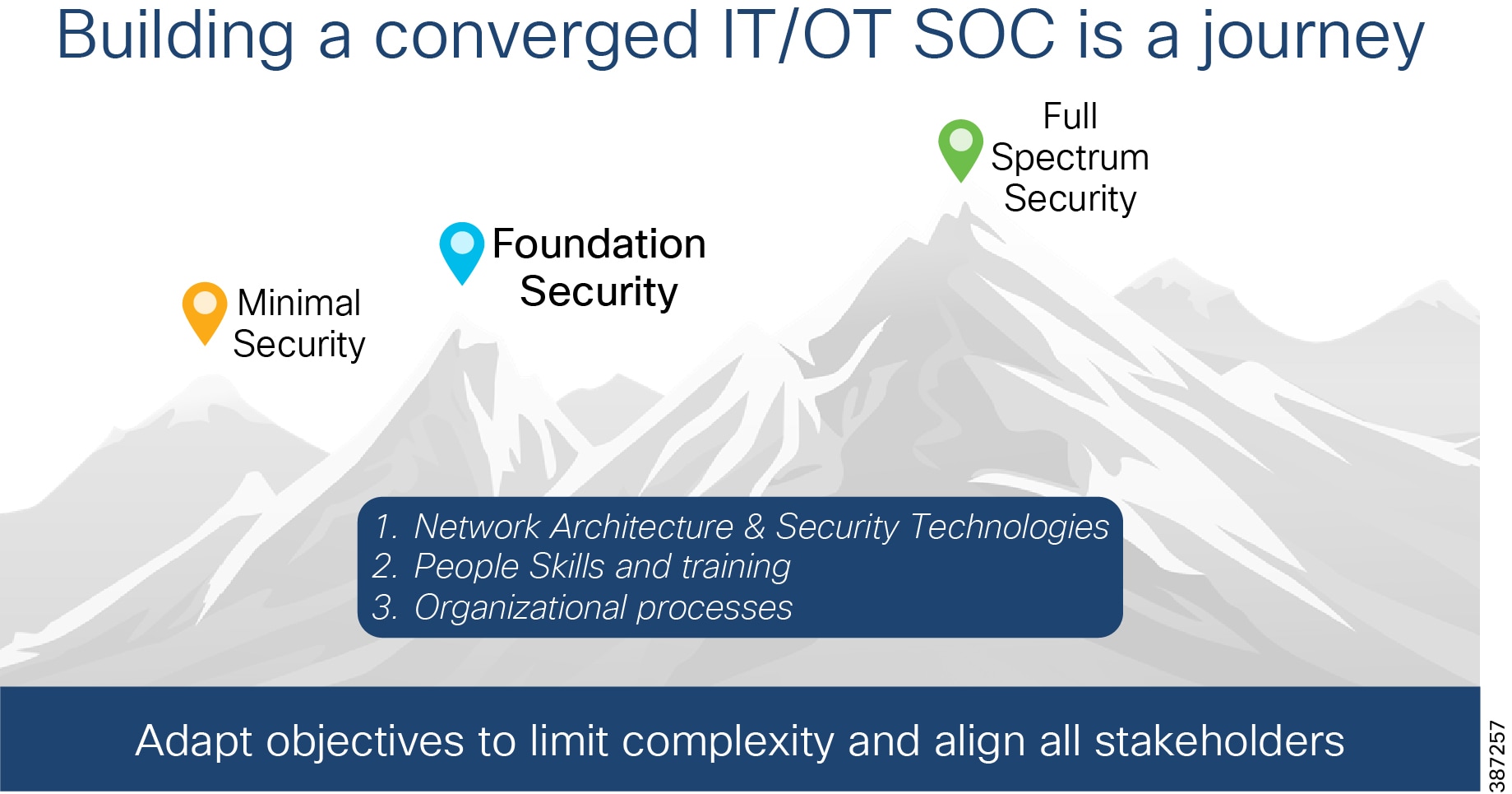
This guide is a Cisco Validated Design (CVD) that provides design guidelines for the Industrial Foundation security design defined in the Securing Industrial Networks solution brief ( https://www.cisco.com/c/en/us/td/docs/solutions/Verticals/Solution_Briefs/Manufacturing_Security_Solution_Brief.html). The solution brief highlights three designs that are additive. The intent is for customers to apply these designs successively to their industrial networks to enhance their cyber security posture. Security Journey shows the security journey that moves through these three stages:
■![]() Minimal Security—Consists of configuring an industrial demilitarized zone (IDMZ) to separate the industrial and enterprise networks.
Minimal Security—Consists of configuring an industrial demilitarized zone (IDMZ) to separate the industrial and enterprise networks.
■![]() Foundation Security—Provides for industrial asset visibility, zone segmentation, zone access control, intrusion detection, threat detection, and response.
Foundation Security—Provides for industrial asset visibility, zone segmentation, zone access control, intrusion detection, threat detection, and response.
■![]() Full Spectrum Security—Builds on the Foundation design, providing a blueprint for a highly digitized, centrally managed, secured, robust, and reliable industrial network. In addition to the capabilities of the Foundation Security design, it supports micro-segmentation, additional network anomaly detection, fine-grained access controls to devices, and DNS security.
Full Spectrum Security—Builds on the Foundation design, providing a blueprint for a highly digitized, centrally managed, secured, robust, and reliable industrial network. In addition to the capabilities of the Foundation Security design, it supports micro-segmentation, additional network anomaly detection, fine-grained access controls to devices, and DNS security.
This guide elaborates on the architecture and design of the Foundation Security Architecture. The following list summarizes the security features enabled by the practices and recommendations in this design guide:
■![]() Segmentation via industrial firewalls
Segmentation via industrial firewalls
■![]() Threat detection and response
Threat detection and response
■![]() Enables coordination with information security for consistent access policy management and aggregation of industrial security events in the security operations center (SOC).
Enables coordination with information security for consistent access policy management and aggregation of industrial security events in the security operations center (SOC).
Primary Security Challenges for Industrial Networks
Analysis of several cyber-attacks on industrial networks has highlighted four items that need to be addressed:
■![]() Asset visibility—Covers the capabilities required to recognize what devices and network elements make up the industrial network. It also covers the communication flows between the assets.
Asset visibility—Covers the capabilities required to recognize what devices and network elements make up the industrial network. It also covers the communication flows between the assets.
■![]() Malware protection—Malware has been very disruptive and there are multiple vectors for malware infection. A critical capability is the ability to detect and contain the spread of malware and other intrusions. This is where network segmentation becomes a critical aspect of cyber-security defense.
Malware protection—Malware has been very disruptive and there are multiple vectors for malware infection. A critical capability is the ability to detect and contain the spread of malware and other intrusions. This is where network segmentation becomes a critical aspect of cyber-security defense.
■![]() Effective workflows between operations and IT/InfoSec—As operational networks are more connected and hence susceptible to cyber-attacks, industrial network administrators can leverage the knowledge and experience of their organization’s Information Security teams and build collaborative workflows to defend against such attacks.
Effective workflows between operations and IT/InfoSec—As operational networks are more connected and hence susceptible to cyber-attacks, industrial network administrators can leverage the knowledge and experience of their organization’s Information Security teams and build collaborative workflows to defend against such attacks.
■![]() Operational complexity—OT personnel face increased complexity because of added security procedures. While there is no silver bullet, there are mechanisms to alleviate the burden of additional complexity.
Operational complexity—OT personnel face increased complexity because of added security procedures. While there is no silver bullet, there are mechanisms to alleviate the burden of additional complexity.
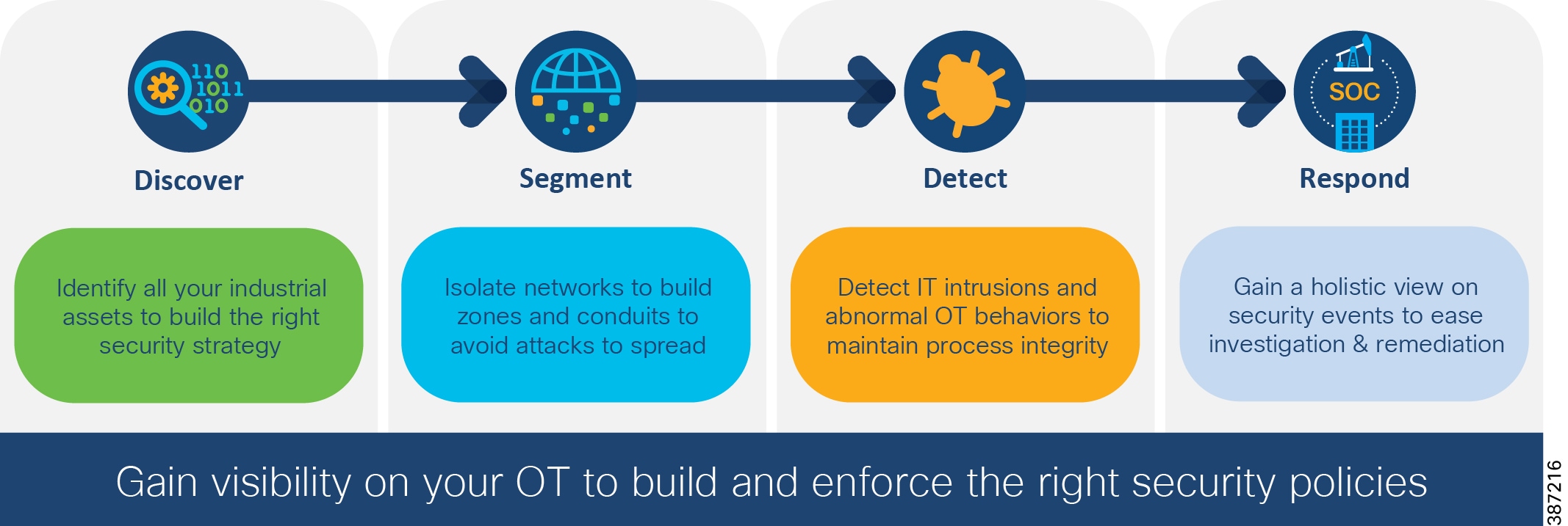
Key Requirements for Securing the Industrial Network depicts the key requirements for securing industrial networks and is used to guide the development of a security lifecycle process. This CVD provides design considerations and recommended Cisco solutions for each of these foundational requirements.
Figure 2 Key Requirements for Securing the Industrial Network
The foundation security design focuses on enabling security use cases in industrial automation environments. It uses the network design for Control Hierarchy (reference ISBN 1-55617-265-6). For details on Industrial Automation network design, refer to Networking and Security in Industrial Automation Environments Design and Implementation Guide ( https://www.cisco.com/c/en/us/td/docs/solutions/Verticals/Industrial_Automation/IA_Horizontal/DG/Industrial-AutomationDG.html). Information on network management and other networking aspects such as redundancy are described in detail in this document.
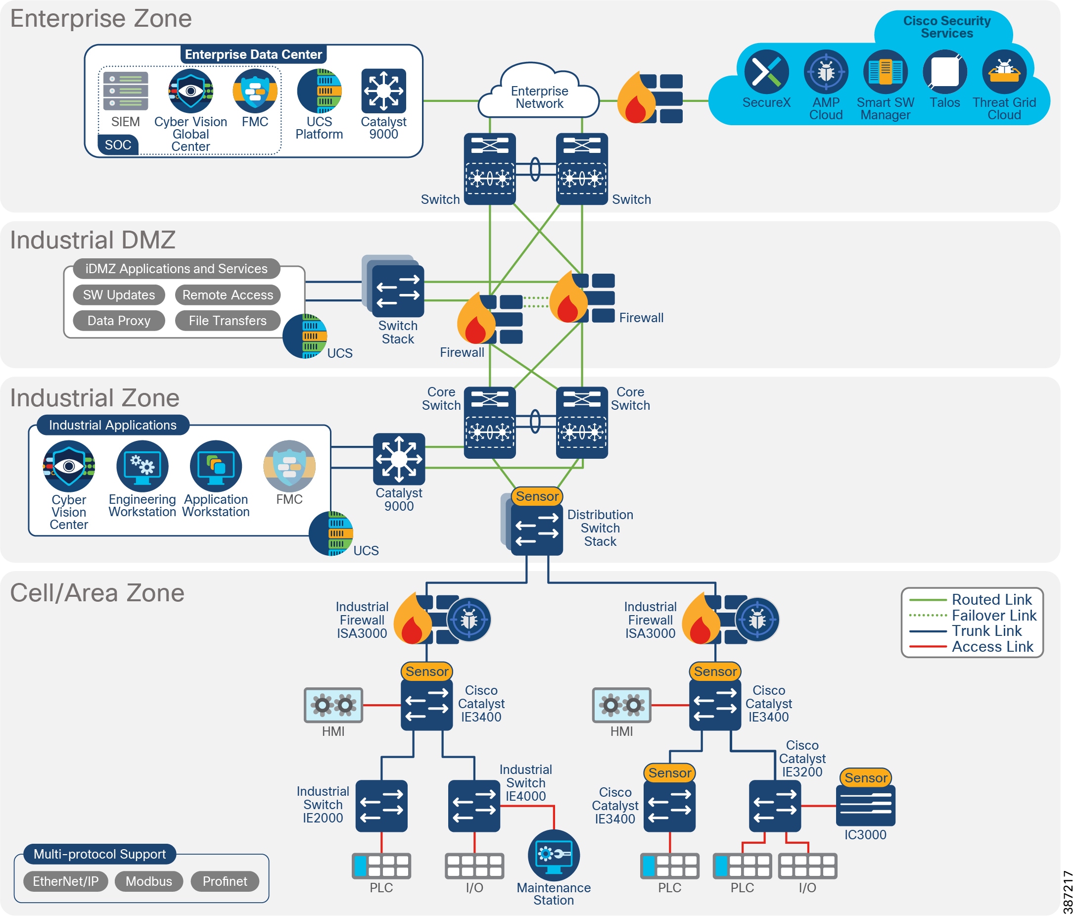
Industrial Foundation Security Architecture depicts a foundation security architecture for industrial networks.
Figure 3 Industrial Foundation Security Architecture1
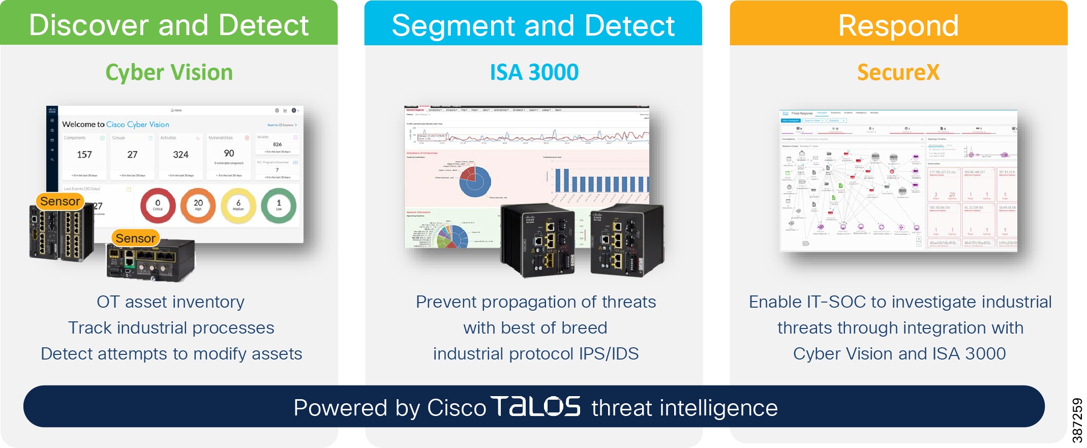
The primary components added to the industrial automation network are described in Components of Industrial Foundation Security and listed below:
■![]() Cisco Cyber Vision provides capabilities for discovery of assets and communication flows. It also supports visibility into industrial protocols to provide capabilities to detect industrial process baselines and changes to them.
Cisco Cyber Vision provides capabilities for discovery of assets and communication flows. It also supports visibility into industrial protocols to provide capabilities to detect industrial process baselines and changes to them.
■![]() Cisco Industrial Security Appliance ISA 3000 provides industrial firewall capabilities for detecting intrusions and supports Cisco Advanced Malware Protection (AMP).
Cisco Industrial Security Appliance ISA 3000 provides industrial firewall capabilities for detecting intrusions and supports Cisco Advanced Malware Protection (AMP).
■![]() Cisco Firepower Management Center (FMC) is used to manage ISA3000.
Cisco Firepower Management Center (FMC) is used to manage ISA3000.
■![]() Cisco SecureX supports intelligence aggregation from various sources and helps run security case management.
Cisco SecureX supports intelligence aggregation from various sources and helps run security case management.
These components work together to provide the key requirements in Key Requirements for Securing the Industrial Network. This document starts by describing the discover requirement, showing how Cisco Cyber Vision is critical for industrial asset visibility. It continues with the segment requirement, positioning ISA 3000 managed by FMC to provide access control, as well as intrusion protection and support for Cisco Advanced Malware Protection. ISA 3000 provides containment for malware within a zone, The document then combines detect and respond in a single section where it is explained how the aforementioned security components provide anomaly detection, intrusion prevention, and tools to investigate and remediate security threats.
Figure 4 Components of Industrial Foundation Security
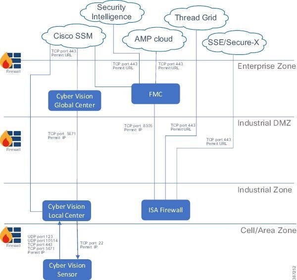
Security Components Communication Flows illustrates the network flows between the security components. It is provided as a reference that you can review as you move through the document.
Figure 5 Security Components Communication Flows
Hardware and Software Matrix
Organization of this Guide
This document is organized by the key requirements for securing industrial networks as depicted in Key Requirements for Securing the Industrial Network:
Each section covers solution components, design considerations, and use cases.
Discover
Discovery of assets and flows provides visibility into the network. The key requirements to consider for discovery are:
■![]() Visibility and identification of all assets on the plant floor.
Visibility and identification of all assets on the plant floor.
■![]() Identification of devices attributes, such as device type, manufacturer, and OS.
Identification of devices attributes, such as device type, manufacturer, and OS.
■![]() Discovery of communication flows between devices.
Discovery of communication flows between devices.
■![]() Detection of known vulnerabilities in assets.
Detection of known vulnerabilities in assets.
■![]() Discovery activities should have no impact on network operation.
Discovery activities should have no impact on network operation.
■![]() Discovery activities should have no negative impact on end devices.
Discovery activities should have no negative impact on end devices.
There are two approaches to network discovery:
■![]() Active approach searches for devices in the network by sending broadcast messages and provides more information about system and application vulnerabilities.
Active approach searches for devices in the network by sending broadcast messages and provides more information about system and application vulnerabilities.
■![]() Passive (or monitoring) approach allows security personnel to monitor which devices are connected, which OSes they are using, what is being sent to, from, and within the system, which services are available, and where parts of the system may be vulnerable to security threats.
Passive (or monitoring) approach allows security personnel to monitor which devices are connected, which OSes they are using, what is being sent to, from, and within the system, which services are available, and where parts of the system may be vulnerable to security threats.
Cisco Cyber Vision is introduced in this design to achieve the objectives listed above. All Cisco Cyber Vision Sensors perform passive discovery when added to the network. Starting with Release 3.2.0, active discovery is also supported. Characteristics of Discovery Mechanisms describes the characteristics of the two discovery mechanisms and how they apply to Cisco Cyber Vision. For maximum visibility, it is possible to enable active discovery in selected presets.
Note: Cisco Stealthwatch and Cisco Industrial Network Director are also visibility tools in the Cisco portfolio. They are complementary technologies. Although they are not included in the foundation industrial security design, Appendix A—Comparison of Cisco Cyber Vision, Cisco Industrial Network Director, and Cisco Stealthwatch provides a comparative table for reference.
As mentioned above, Cisco Cyber Vision is used as the discovery component of this design. The discover section of this document covers the following topics:
■![]() Cisco Cyber Vision Overview—Introduces Cisco Cyber Vision and its value proposition.
Cisco Cyber Vision Overview—Introduces Cisco Cyber Vision and its value proposition.
■![]() Cisco Cyber Vision Components—Explains the three components.
Cisco Cyber Vision Components—Explains the three components.
■![]() Design Considerations—Covers licensing options, deployment modes, placement in the network, and considerations when deploying Cisco Cyber Vision in industrial automation environments.
Design Considerations—Covers licensing options, deployment modes, placement in the network, and considerations when deploying Cisco Cyber Vision in industrial automation environments.
■![]() Discover Use Cases—Showcases how Cisco Cyber Vision can be used to enable discovery use cases.
Discover Use Cases—Showcases how Cisco Cyber Vision can be used to enable discovery use cases.
Cisco Cyber Vision Overview
Cisco Cyber Vision is an industrial cybersecurity solution specifically designed to ensure continuity, resilience, and safety of industrial operations. It provides asset owners with full visibility into their industrial automation and control systems (IACS) networks so they can ensure operational and process integrity, drive regulatory compliance, and enable easy deployment within the industrial network. Cisco Cyber Vision leverages Cisco industrial network equipment to monitor industrial operations and feeds other Cisco IT security platforms with OT context (e.g., IACS device information) to build a unified IT/OT cybersecurity architecture.
Cisco Cyber Vision Key Features
■![]() Security built Into your industrial network —Cisco Cyber Vision leverages a unique edge computing architecture that enables security monitoring components to run within Cisco industrial network equipment (IoT switches, routers, access points, industrial compute, and so on). There is no need to span/copy raw network traffic to dedicated security appliances and consider the impact on real production networks or build an expensive out-of-band networks to provide visibility of industrial network flows. Cisco Cyber Vision operating in the industrial network collects and analyzes the information required to provide comprehensive visibility, analytics, and threat detection.
Security built Into your industrial network —Cisco Cyber Vision leverages a unique edge computing architecture that enables security monitoring components to run within Cisco industrial network equipment (IoT switches, routers, access points, industrial compute, and so on). There is no need to span/copy raw network traffic to dedicated security appliances and consider the impact on real production networks or build an expensive out-of-band networks to provide visibility of industrial network flows. Cisco Cyber Vision operating in the industrial network collects and analyzes the information required to provide comprehensive visibility, analytics, and threat detection.
■![]() Visibility of the OT network —Cisco Cyber Vision automatically uncovers the smallest details of the production infrastructure: vendor references, firmware and hardware versions, serial numbers, PLC rack slot configuration, and so on. It identifies asset relationships, communication patterns, changes to variables, and more. This wealth of information is shown in various types of maps, tables, and reports that maintain a complete inventory of industrial assets, their relationships, their vulnerabilities, and the programs they run.
Visibility of the OT network —Cisco Cyber Vision automatically uncovers the smallest details of the production infrastructure: vendor references, firmware and hardware versions, serial numbers, PLC rack slot configuration, and so on. It identifies asset relationships, communication patterns, changes to variables, and more. This wealth of information is shown in various types of maps, tables, and reports that maintain a complete inventory of industrial assets, their relationships, their vulnerabilities, and the programs they run.
■![]() View communication flows —Cisco Cyber Vision gives OT engineers real-time insight into the industrial flow, such as unexpected variable changes or controller modifications. They can take action to maintain system integrity and production continuity. Cyber experts can easily analyze this data for anomalies.
View communication flows —Cisco Cyber Vision gives OT engineers real-time insight into the industrial flow, such as unexpected variable changes or controller modifications. They can take action to maintain system integrity and production continuity. Cyber experts can easily analyze this data for anomalies.
■![]() Industrial protocol support —Cisco Cyber Vision “understands” the proprietary OT protocols used by automation equipment, so it can track process anomalies, errors, misconfigurations, and unauthorized industrial events. It also records everything and so serves as a kind of “flight recorder” of the industrial infrastructure.
Industrial protocol support —Cisco Cyber Vision “understands” the proprietary OT protocols used by automation equipment, so it can track process anomalies, errors, misconfigurations, and unauthorized industrial events. It also records everything and so serves as a kind of “flight recorder” of the industrial infrastructure.
■![]() Threat detection —As attacks on industrial networks generally look like legitimate instructions to assets, you also need to detect those unwanted process modifications. Cisco Cyber Vision combines protocol analysis, intrusion detection, and behavioral analysis to detect attack tactics.
Threat detection —As attacks on industrial networks generally look like legitimate instructions to assets, you also need to detect those unwanted process modifications. Cisco Cyber Vision combines protocol analysis, intrusion detection, and behavioral analysis to detect attack tactics.
Cisco Cyber Vision Components
Cisco Cyber Vision has the following components:
■![]() Edge Sensors which are installed in the industrial network. These sensors are dedicated to capture network traffic, decode protocols using the Cisco Deep Packet inspection engine, and send meaningful information to the Cisco Cyber Vision Center.
Edge Sensors which are installed in the industrial network. These sensors are dedicated to capture network traffic, decode protocols using the Cisco Deep Packet inspection engine, and send meaningful information to the Cisco Cyber Vision Center.
■![]() Cisco Cyber Vision Center, a central platform gathering data from all the Edge Sensors and acting as the monitoring, detection, and management platform.
Cisco Cyber Vision Center, a central platform gathering data from all the Edge Sensors and acting as the monitoring, detection, and management platform.
■![]() Global Center, an optional component to which all Centers are connected, for a central view of all Centers deployed within an organization for alerting, reporting, and management functions.
Global Center, an optional component to which all Centers are connected, for a central view of all Centers deployed within an organization for alerting, reporting, and management functions.
Cisco Cyber Vision Center
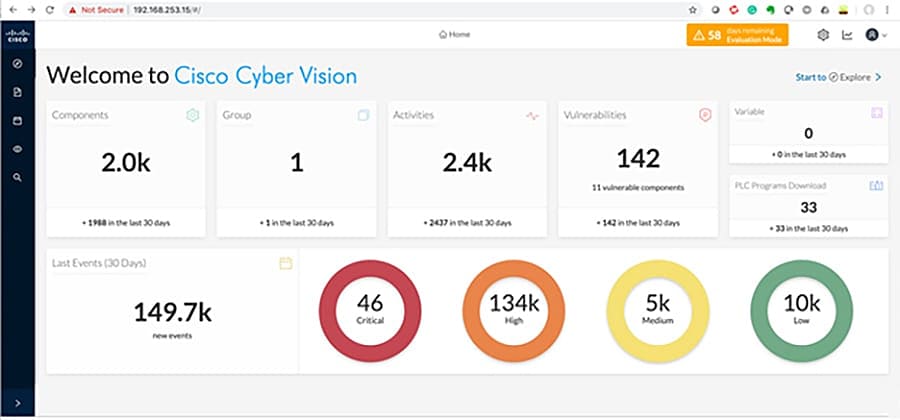
Cisco Cyber Vision Center is an application that can be installed as a virtual machine or as a hardware appliance. The Center provides easy-to-follow visualization that allows an OT operator to gain visibility into the networked devices, especially the IACS devices. Cisco Cyber Vision Center Dashboard shows a high-level overview of the Cisco Cyber Vision Center dashboard.
Figure 6 Cisco Cyber Vision Center Dashboard
The Cisco Cyber Vision Center provides the following functions:
■![]() Dynamic inventory—Cisco Cyber Vision Center generates a dynamic inventory of all the IACS devices on the plant floor. The Cisco Cyber Vision Sensor continuously listens to the events happening on the plant floor, thereby allowing the Cisco Cyber Vision Center to build and update the dynamic inventory of the devices in the plant floor. This enables a live list of active devices to be viewed by time segments.
Dynamic inventory—Cisco Cyber Vision Center generates a dynamic inventory of all the IACS devices on the plant floor. The Cisco Cyber Vision Sensor continuously listens to the events happening on the plant floor, thereby allowing the Cisco Cyber Vision Center to build and update the dynamic inventory of the devices in the plant floor. This enables a live list of active devices to be viewed by time segments.
■![]() Intuitive filters—Cisco Cyber Vision Center provides intuitive filters labeled as presets to help an OT operator examine data. For example, an operator may want to look at the current list of OT components reading variables. Cyber Vision Center allows access to the OT component preset and filter by activity tag to observe only desired information.
Intuitive filters—Cisco Cyber Vision Center provides intuitive filters labeled as presets to help an OT operator examine data. For example, an operator may want to look at the current list of OT components reading variables. Cyber Vision Center allows access to the OT component preset and filter by activity tag to observe only desired information.
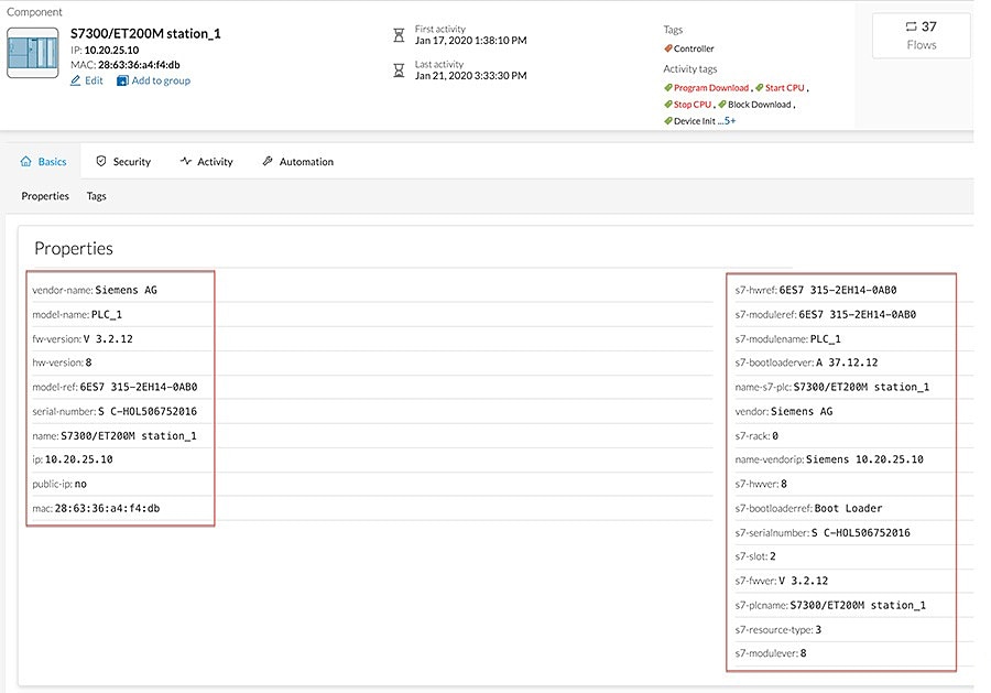
■![]() Detailed IACS asset information—One of the significant advantages of the Cisco Cyber Vision solution is the ability to glean very detailed information about IACS assets. Example of Detailed Asset Information for Siemens Controller displays information about a Siemens controller.
Detailed IACS asset information—One of the significant advantages of the Cisco Cyber Vision solution is the ability to glean very detailed information about IACS assets. Example of Detailed Asset Information for Siemens Controller displays information about a Siemens controller.
Figure 7 Example of Detailed Asset Information for Siemens Controller
■![]() Baselining—Cisco Cyber Vision Center supports a feature called baselining, which allows an operator to select a set of components to monitor. The operator can create a reference for monitored components during normal operation called baseline. After a baseline is defined, the operator can compare the changes that happened to this set of elements at different times to determine if changes have occurred that indicate a risk or compromise.
Baselining—Cisco Cyber Vision Center supports a feature called baselining, which allows an operator to select a set of components to monitor. The operator can create a reference for monitored components during normal operation called baseline. After a baseline is defined, the operator can compare the changes that happened to this set of elements at different times to determine if changes have occurred that indicate a risk or compromise.
■![]() Vulnerability management—Cisco Cyber Vision Center highlights known firmware/software vulnerabilities that are present in IACS devices, which helps an operator to mitigate those vulnerabilities.
Vulnerability management—Cisco Cyber Vision Center highlights known firmware/software vulnerabilities that are present in IACS devices, which helps an operator to mitigate those vulnerabilities.
■![]() Reports—Cisco Cyber Vision allows an operator to generate inventory, activity, vulnerability, and PLC (Programmable Logic Controller) reports.
Reports—Cisco Cyber Vision allows an operator to generate inventory, activity, vulnerability, and PLC (Programmable Logic Controller) reports.
■![]() Dynamic maps—Cisco Cyber Vision Center provides very detailed maps that display the components and the communication flows between them.
Dynamic maps—Cisco Cyber Vision Center provides very detailed maps that display the components and the communication flows between them.
Cisco Cyber Vision Global Center
Cisco Cyber Vision Global Center is an application that can be optionally installed as a virtual machine or as a hardware appliance. Multiple Cisco Cyber Vision Centers can enroll on a single Cisco Cyber Vision Global Center for global visibility and an aggregated view of asset inventory, vulnerabilities, and activities. It provides a consolidated view for multisite, large-scale Cyber Vision deployments.
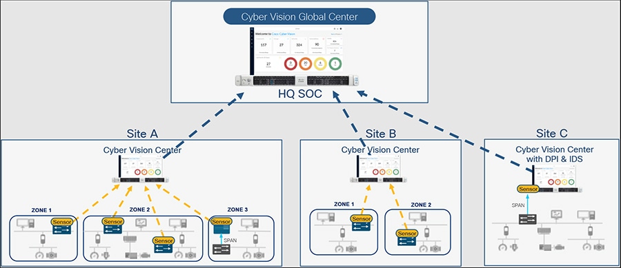
The Global Center feature gives global visibility on all industrial assets and security events across several sites from a central console. Cisco Cyber Vision Distributed Architecture shows how Cisco Cyber Vision Global Center connects to multiple Cisco Cyber Vision Centers to provide a unified view of assets and events across sites.
Figure 8 Cisco Cyber Vision Distributed Architecture
Besides consolidated visibility of components across sites, the Cisco Cyber Vision Global Center provides centralized management of Knowledge Database (KDB) updates. KDB contains a list of recognized vulnerabilities, icons, threats, and so on. KDB will be covered in detail in Cisco Cyber Vision Knowledge Database and Respond Best Practices.
Cisco Cyber Vision Sensor
The Cyber Vision Sensor monitors operational network traffic and performs deep packet inspection to discover IACS assets, traffic flows, and vulnerabilities. The sensor forwards metadata such as device attributes, packet headers, and operational events to the Cyber Vision Center, which does not significantly impact network bandwidth utilization. Two interfaces are used by the sensor: one for management communication and a second for data capture. The management interface is used by the Cyber Vision Sensor to send the metadata to the Cyber Vision Center and the capture interface receives Switched Port Analyzer (SPAN) traffic for inspection. It is recommended to configure the management interface within the switch management VLAN.
In this guide, two types of Cisco Cyber Vision Sensors were validated:
■![]() Network sensor—Cisco Cyber Vision Sensor embedded as an IOx application on the Cisco IE3300 with 10G uplinks variants, IE3400, and Catalyst 9300 switches.
Network sensor—Cisco Cyber Vision Sensor embedded as an IOx application on the Cisco IE3300 with 10G uplinks variants, IE3400, and Catalyst 9300 switches.
■![]() Hardware sensor—Cisco IC3000 with Cisco Cyber Vision Sensor installed as an IOx application.
Hardware sensor—Cisco IC3000 with Cisco Cyber Vision Sensor installed as an IOx application.
The Cyber Vision network sensor is a software-based solution in the Industrial Automation network. It captures traffic flowing through the network device and sends it to the sensor application. It can analyze all communication from monitored network links. The network sensor deployed in the industrial switches can monitor all communication flows to and from IACS devices, directly connected to the device or not. The advantages of deploying a network-based sensor are:
■![]() Reduce or eliminate the need to span or copy traffic on production networks competing with production traffic or over expensive overlay networks.
Reduce or eliminate the need to span or copy traffic on production networks competing with production traffic or over expensive overlay networks.
■![]() If the network is already using switches that support network sensors, an operations engineer from the Level 3 Site Operations Zone can install the network sensor remotely.
If the network is already using switches that support network sensors, an operations engineer from the Level 3 Site Operations Zone can install the network sensor remotely.
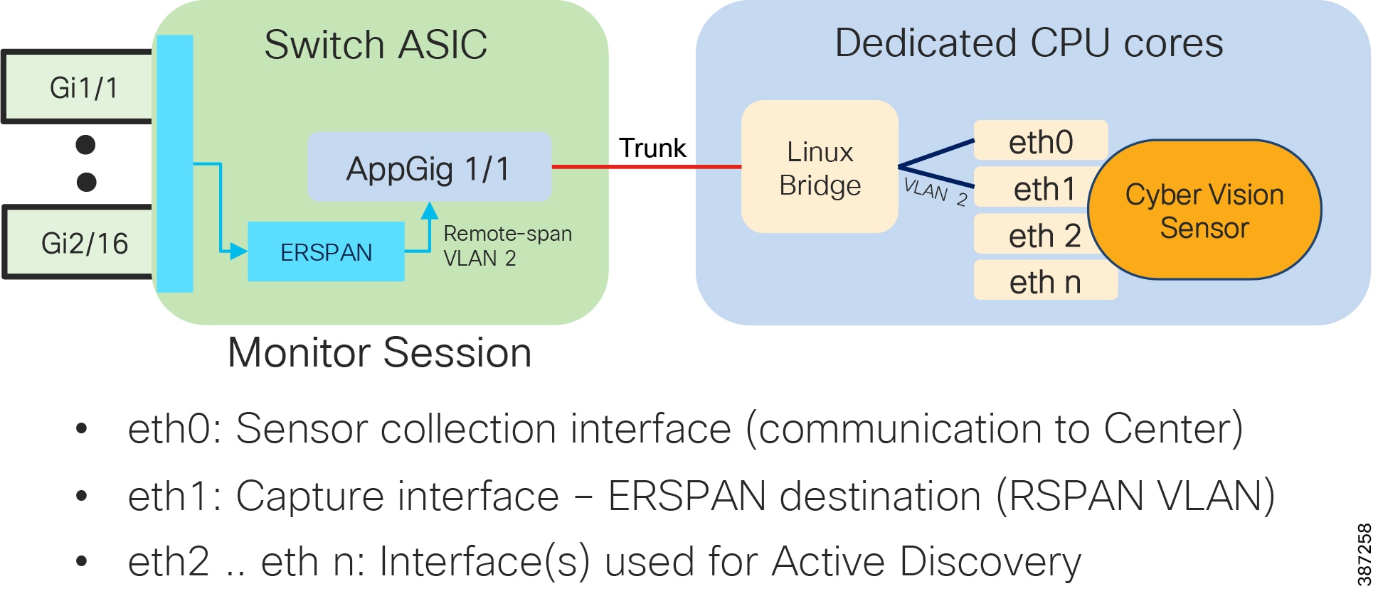
Network Sensor on Cisco Catalyst IE3400 and Cisco Catalyst IE3300 10G shows a Cisco Cyber Vision Sensor running on Catalyst IE3400 or Catalyst IE3300 10G. The sensor application has a minimum of two virtual interfaces: eth0 is used for communication with the center and eth1 is the capture interface which is configured on the RSPAN VLAN on the switch (ERSPAN Destination). Additional interfaces can be created for active discovery on different subnets. On the switch side, the AppGig1/1 interface is configured as a trunk to provide connectivity to sensor interfaces. The RSPAN VLAN can be private to the switch. A monitor session is created to copy traffic flowing on physical interfaces or VLANs into the RSPAN VLAN.
Figure 9 Network Sensor on Cisco Catalyst IE3400 and Cisco Catalyst IE3300 10G
The Cisco IC3000 is an industrial compute platform capable of having four physical interfaces in addition to the management Ethernet interface. When Cisco IC3000 is deployed as a hardware sensor, the management interface is used to transport the information to the Cisco Cyber Vision Center; the four interfaces are used for data collection. For the sensor to get the traffic on the collection interface a SPAN or RSPAN (Remote SPAN) session needs to be configured on switches on the traffic path.
For additional Cisco Cyber Vision documentation see:
https://www.cisco.com/c/en/us/support/security/cyber-vision/series.html#Design.
Design Considerations
This section discusses the critical design considerations that must be taken into account while deploying Cisco Cyber Vision solutions in industrial automation environments. The Industrial Security design has a Cisco Cyber Vision Global Center in the Enterprise Zone to provide global visibility of components in multiple industrial zones. Cyber Vision Center is installed in the Industrial Zone; besides being a critical application, its constant communication with the sensors on the plant floor require it to be installed in the operations area. Finally, sensors are deployed in the Cell/Area Zone; they provide network visibility at the edge, avoiding the need for collection appliances and a SPAN collection network.
Licensing Options
Cisco Cyber Vision Center requires a license. Licenses must be available in the smart account to register product instances. The following options are available:
■![]() Direct cloud access to Cisco Smart Software Manager (SSM)—Cisco product sends usage directly over internet.
Direct cloud access to Cisco Smart Software Manager (SSM)—Cisco product sends usage directly over internet.
■![]() Direct cloud access via https proxy—Cisco product uses a proxy to send information to SSM.
Direct cloud access via https proxy—Cisco product uses a proxy to send information to SSM.
■![]() Cisco Smart Software Manager On-Prem—Usage information sent to a local appliance, information is periodically sent to CSSM.
Cisco Smart Software Manager On-Prem—Usage information sent to a local appliance, information is periodically sent to CSSM.
■![]() Offline—Licenses are reserved in SSM and applied manually to devices.
Offline—Licenses are reserved in SSM and applied manually to devices.
The four licensing options are supported by Cisco Cyber Vision. The option validated in this design is the direct cloud access, in which products use port 443 to register to SSM. The following section provides an introduction to Smart Software Manager On-Prem for deployments with restricted cloud connectivity. Although it was not the validated option, costumers should consider SSM On-Prem.
Cisco Smart Software Manager On-Prem
Formerly known as Cisco Smart Software Manager satellite, it is a component of Cisco Smart Licensing that works in conjunction with Cisco Smart Software Manager. It offers near real-time visibility and reporting of the Cisco licenses you purchase and consume while giving security-sensitive organizations a way to access a subset of Cisco SSM functionality without using a direct Internet connection to manage their install base.
Note: On-Prem must synchronize with Cisco SSM periodically to reflect your latest license entitlements. It can be directly connected to Cisco.com or disconnected but synchronized with Cisco SSM via file upload and download.
The following are the required ports:
Cisco Cyber Vision Global Center Considerations
■![]() Cisco Cyber Vision Global Center can aggregate up to 10 Cisco Cyber Vision Centers, making it an ideal fit for large deployments where multiple Centers are deployed.
Cisco Cyber Vision Global Center can aggregate up to 10 Cisco Cyber Vision Centers, making it an ideal fit for large deployments where multiple Centers are deployed.
■![]() In the Industrial Security design, the Cisco Cyber Vision Global Center is deployed in the Enterprise Zone, while the Cisco Cyber Vision Center is deployed on the Industrial Zone. This deployment provides a consolidated view of multiple production networks on a single Global Center.
In the Industrial Security design, the Cisco Cyber Vision Global Center is deployed in the Enterprise Zone, while the Cisco Cyber Vision Center is deployed on the Industrial Zone. This deployment provides a consolidated view of multiple production networks on a single Global Center.
■![]() Cisco Cyber Vision Global Center does not require an additional license.
Cisco Cyber Vision Global Center does not require an additional license.
■![]() Cisco Cyber Vision Global Center requires only one interface for management and communication with Cisco Cyber Vision Center instances. It uses TCP port 5671 for synchronization and updates to the Center. This port should be proxied in the iDMZ or enabled in the iDMZ firewall to ease communication.
Cisco Cyber Vision Global Center requires only one interface for management and communication with Cisco Cyber Vision Center instances. It uses TCP port 5671 for synchronization and updates to the Center. This port should be proxied in the iDMZ or enabled in the iDMZ firewall to ease communication.
■![]() Cyber Vision Global Center is used for security monitoring across multiple sites, providing a consolidated view of components, vulnerabilities, and events. Nevertheless, sensor operation and management activities can be done only on instances of Cyber Vision Center associated with the sensor.
Cyber Vision Global Center is used for security monitoring across multiple sites, providing a consolidated view of components, vulnerabilities, and events. Nevertheless, sensor operation and management activities can be done only on instances of Cyber Vision Center associated with the sensor.
■![]() On Cyber Vision Release 3.2.0 or earlier, a Cyber Vision Center must be enrolled to a Cisco Cyber Vision Global Center during installation. Cyber Vision Centers cannot be associated to a Global Center after installation. Starting in Release 3.2.1, a Cisco Cyber Vision Center can be deployed and operated before enrollment to its Global Center.
On Cyber Vision Release 3.2.0 or earlier, a Cyber Vision Center must be enrolled to a Cisco Cyber Vision Global Center during installation. Cyber Vision Centers cannot be associated to a Global Center after installation. Starting in Release 3.2.1, a Cisco Cyber Vision Center can be deployed and operated before enrollment to its Global Center.
■![]() Cisco Cyber Vision Global Center should not be disconnected from Cisco Cyber Vision Center for long periods of time. For small sites (less than 1000 components), maximum disconnected time is one month. For larger sites maximum disconnected time is one week.
Cisco Cyber Vision Global Center should not be disconnected from Cisco Cyber Vision Center for long periods of time. For small sites (less than 1000 components), maximum disconnected time is one month. For larger sites maximum disconnected time is one week.
■![]() Cisco Cyber Vision Global Center does not provide for the creation of a single flow from two separated flows coming from different Cisco Cyber Vision Centers, for example if there are cross-site communication flows.
Cisco Cyber Vision Global Center does not provide for the creation of a single flow from two separated flows coming from different Cisco Cyber Vision Centers, for example if there are cross-site communication flows.
Cisco Cyber Vision Center Considerations
■![]() Cisco Cyber Vision Center can be deployed as a software or hardware appliance depending on your network requirements. Consider the number of sensors, components, and flows to decide the appropriate installation. Refer to:
Cisco Cyber Vision Center can be deployed as a software or hardware appliance depending on your network requirements. Consider the number of sensors, components, and flows to decide the appropriate installation. Refer to:
https://www.cisco.com/c/en/us/products/collateral/se/internet-of-things/datasheet-c78-743222.html#Platformsupport for scale numbers.
■![]() Cisco Cyber Vision Center uses TCP port 5671 for synchronization and updates to Cisco Cyber Vision Global Center. This port should be proxied in the iDMZ or enabled in the iDMZ firewall to ease communication.
Cisco Cyber Vision Center uses TCP port 5671 for synchronization and updates to Cisco Cyber Vision Global Center. This port should be proxied in the iDMZ or enabled in the iDMZ firewall to ease communication.
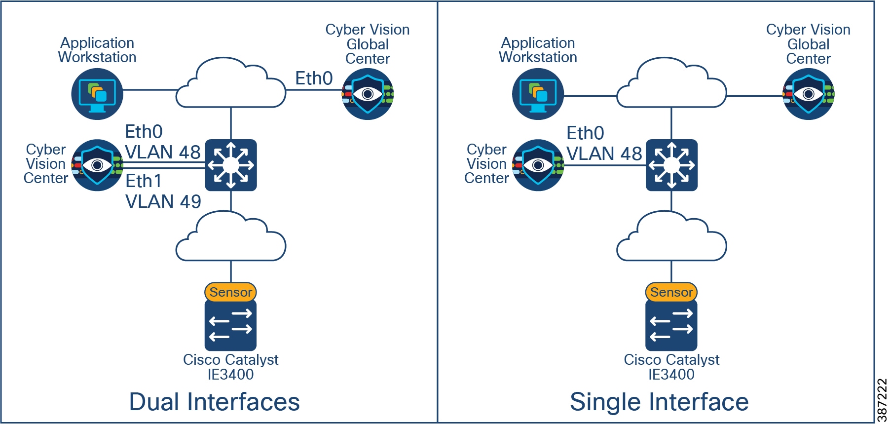
■![]() It is recommended to install Cisco Cyber Vision Center with dual interfaces connected to two separate subnets, user access and sensor collection. However, in case of incompatibility with the industrial network infrastructure, you can use a single network interface (eth0). Online Mode Deployment in Cell/Area Zone shows interface deployment options. When deploying using dual network:
It is recommended to install Cisco Cyber Vision Center with dual interfaces connected to two separate subnets, user access and sensor collection. However, in case of incompatibility with the industrial network infrastructure, you can use a single network interface (eth0). Online Mode Deployment in Cell/Area Zone shows interface deployment options. When deploying using dual network:
–![]() The administrator network interface (eth0), which gives access to the user interface.
The administrator network interface (eth0), which gives access to the user interface.
–![]() The Collection network interface (eth1), which connects the Center to the sensors.
The Collection network interface (eth1), which connects the Center to the sensors.
Note: Cisco Cyber Vision Center does not require internet connectivity nor Global Center connectivity to operate. Upgrades need to be downloaded from Cisco.com and uploaded in the appliance.
Figure 10 Cisco Cyber Vision Center Interfaces
Cisco Cyber Vision Sensors Considerations
Cisco Cyber Vision Sensor Deployment Mode
The Cisco Cyber Vision solution supports two deployment models: offline mode and online mode.
■![]() Cisco Cyber Vision Offline Mode is deployed by an OT engineer when there is no Cisco Cyber Vision Center or there is no Layer 3 communication between the Cisco Cyber Vision Sensors and the Cisco Cyber Vision Center. In these situations, the OT engineer can use offline mode, which involves capturing the data packets using a USB stick and then later analyzing them by manually loading them in the Cisco Cyber Vision Center. This mode is often used to perform security reviews.
Cisco Cyber Vision Offline Mode is deployed by an OT engineer when there is no Cisco Cyber Vision Center or there is no Layer 3 communication between the Cisco Cyber Vision Sensors and the Cisco Cyber Vision Center. In these situations, the OT engineer can use offline mode, which involves capturing the data packets using a USB stick and then later analyzing them by manually loading them in the Cisco Cyber Vision Center. This mode is often used to perform security reviews.
■![]() Cisco Cyber Vision Online mode assumes that there is Layer 3 connectivity between the Cisco Cyber Vision Sensor and the Center. In this guide, we recommend customers use online mode for the following reasons:
Cisco Cyber Vision Online mode assumes that there is Layer 3 connectivity between the Cisco Cyber Vision Sensor and the Center. In this guide, we recommend customers use online mode for the following reasons:
–![]() Online mode ensures that the OT and IT operations teams get a continuous update of traffic in real-time.
Online mode ensures that the OT and IT operations teams get a continuous update of traffic in real-time.
–![]() There is no manual process of capturing the data and uploading the data as discussed in offline mode. The data is captured in real-time at the Cisco Cyber Vision Center.
There is no manual process of capturing the data and uploading the data as discussed in offline mode. The data is captured in real-time at the Cisco Cyber Vision Center.
–![]() Offline mode depends on the available storage space of the USB disk and cannot be used as a solution for long term storage of the data.
Offline mode depends on the available storage space of the USB disk and cannot be used as a solution for long term storage of the data.
Online Mode Deployment in Cell/Area Zone depicts Cyber Vision deployed using the online mode, with sensors deployed in Cell/Area Zones and Cyber Vision Center deployed in the Industrial Zone.
Figure 11 Online Mode Deployment in Cell/Area Zone
Sensor Selection
The recommended option is for customers to deploy the network sensor on the Catalyst IE3400 to provide visibility for the Cell/Area Zone. A sensor is deployed at the edge to capture flows for end devices. Deploying network/hardware sensor at a switch where a controller is attached is an ideal choice to monitor the traffic because all the IO devices respond to the poll requests initiated by the controller. The network sensor on the Catalyst IE3300 with 10G uplinks variants has the same advantages. Consider this option if your network needs additional bandwidth.
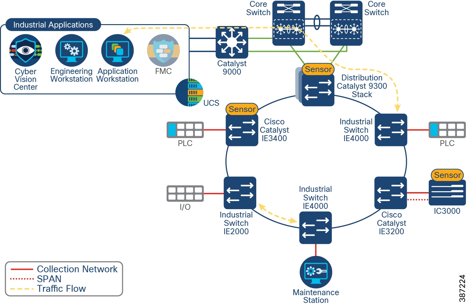
A sensor on the Catalyst 9300 may be installed when it is not possible to install a network sensor on every device in the Cell/Area Zone to capture flows that would be missed otherwise. For example, in ring-based topologies a sensor installed on an industrial switch may miss a communication flow which is not in its traffic path. Deploying a network sensor on the Catalyst 9300 will detect all the inter-cell communication flows and any flows that are coming from the higher layers to the Cell/Area Zone. Sensor Deployment Example illustrates two flows that may be missed with the depicted sensor placement. Installing a sensor on the Catalyst 9300 would provide visibility to the north-south flow. Note that the maintenance station to I/O flow may not be detected if the flow does not cross the distribution switch unless more sensors are deployed.
Figure 12 Sensor Deployment Example
Finally, hardware sensors on IC3000 are an option for brownfield deployments where it is not possible to have switches that support a network sensor. Hardware sensors require SPAN or RSPAN to be enabled to process packets. Cisco IC3000 deployed with Cisco Cyber Vision has two distinct sets of interfaces: collection interface and mirror interfaces. The collection interface is a Layer 3 interface that is used to transport the metadata to the Center. The mirror interfaces collect the SPAN traffic in the network from one or multiple VLANs.
Capture Options
The control system engineer must be careful when deciding the correct location for the sensor in the network. The Cisco Cyber Vision Sensor uses deep packet inspection to analyze the traffic flows.
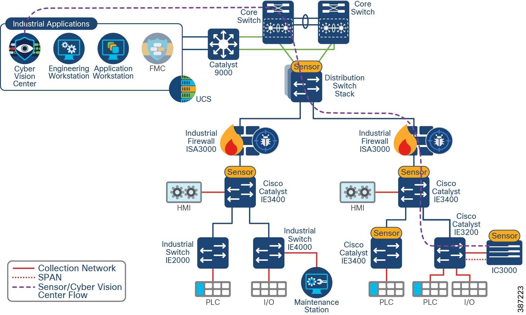
The effectiveness of the Cisco Cyber Vision solution depends on effectively capturing traffic, so deciding where to capture traffic is critical. Deploying a network sensor in the distribution switch using the Catalyst 9300 will capture the north-south traffic. In the Cell/Area Zone, deploying a Sensor at a switch where a controller is attached is an ideal choice to monitor the traffic because all the I/O devices respond to the poll requests initiated by the controller. However, there could be scenarios where there are many controller devices attached to several switches in the network, and if you want to monitor the traffic from all those devices, then you have two main choices as depicted in Sensor Deployment Options.
Figure 13 Sensor Deployment Options
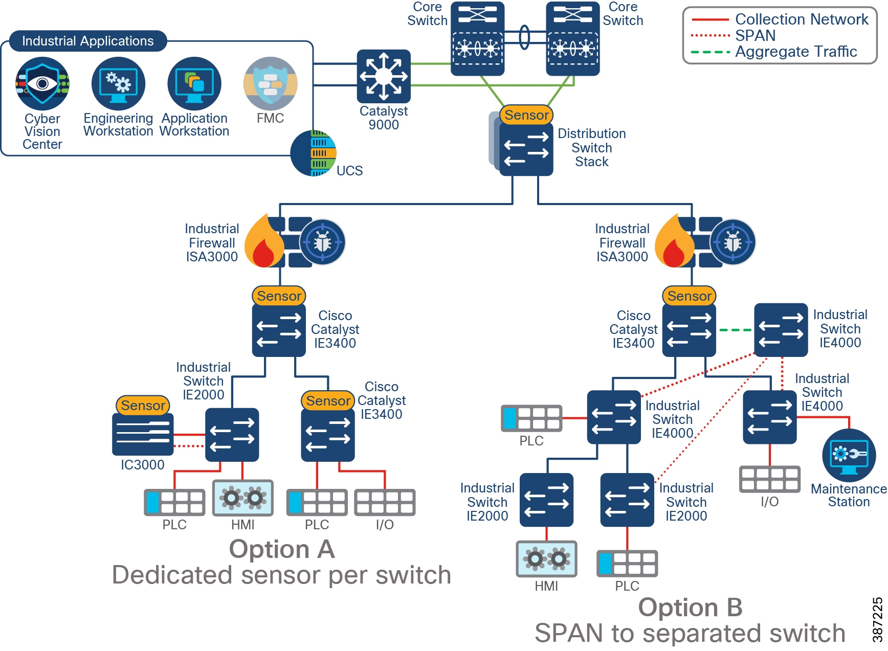
■![]() Option A—Dedicated sensor per switch. To capture all relevant traffic in the Cell/Area Zone, a sensor can be deployed in every switch. It displays a mix of network and hardware sensors depending on platform capability.
Option A—Dedicated sensor per switch. To capture all relevant traffic in the Cell/Area Zone, a sensor can be deployed in every switch. It displays a mix of network and hardware sensors depending on platform capability.
However, it is possible to reduce the number of sensors by, for example, installing only one sensor on the Catalyst IE3400 acting as aggregation. In this case Cyber Vision will get all inter-switch flows but will miss intra-switch communication on access switches.
■![]() Option B—Enable SPAN on switches connected to a separated switch (only for monitoring) that will aggregate traffic and send it to a sensor. This deployment requires a single sensor (hardware or network options are supported). It also requires additional cabling from every device to the aggregation point. As in option A, to capture all traffic, SPAN should be configured in every switch. Sensor Deployment Options shows an example of a switch not being monitored.
Option B—Enable SPAN on switches connected to a separated switch (only for monitoring) that will aggregate traffic and send it to a sensor. This deployment requires a single sensor (hardware or network options are supported). It also requires additional cabling from every device to the aggregation point. As in option A, to capture all traffic, SPAN should be configured in every switch. Sensor Deployment Options shows an example of a switch not being monitored.
Option A is the recommended option. If it is not possible to install a sensor at every point, consider placing the sensors to intercept the most critical traffic. If you do not have a brownfield deployment without switches capable of running Cisco Cyber Vision Sensor, consider option B.
Sensor Considerations
■![]() Cisco Cyber Vision Sensors are installed as an IOx application. IOx is included with Essentials and Advanced licenses of Cisco Switches.
Cisco Cyber Vision Sensors are installed as an IOx application. IOx is included with Essentials and Advanced licenses of Cisco Switches.
■![]() IOx applications need an SD card to be installed. SD cards are optional on the switch order configuration. A Cisco supplied SD card of minimum four GB is needed.
IOx applications need an SD card to be installed. SD cards are optional on the switch order configuration. A Cisco supplied SD card of minimum four GB is needed.
■![]() Sensors need an IP address to communicate with the Cisco Cyber Vision Center (collection interface). For network sensors deployed in IOx, this IP address needs to be different from other IP addresses on the switch. Although it can belong to any VLAN on the switch, it is recommended that the IP address is assigned on the management network.
Sensors need an IP address to communicate with the Cisco Cyber Vision Center (collection interface). For network sensors deployed in IOx, this IP address needs to be different from other IP addresses on the switch. Although it can belong to any VLAN on the switch, it is recommended that the IP address is assigned on the management network.
■![]() The sensor also needs a capture interface to reach the monitor session in the switch. This has local significance only, so VLAN used for RSPAN to the sensor should be private to the switch.
The sensor also needs a capture interface to reach the monitor session in the switch. This has local significance only, so VLAN used for RSPAN to the sensor should be private to the switch.
■![]() The following ports are needed for communication between Cisco Cyber Vision Center and Cisco Cyber Vision Sensor:
The following ports are needed for communication between Cisco Cyber Vision Center and Cisco Cyber Vision Sensor:
–![]() From Cisco Cyber Vision Sensor to Cisco Cyber Vision Center
From Cisco Cyber Vision Sensor to Cisco Cyber Vision Center
–![]() From Cisco Cyber Vision Center to Cisco Cyber Vision Sensor
From Cisco Cyber Vision Center to Cisco Cyber Vision Sensor
— (Optional for installation using sensor manager extension) TCP port 443 for network sensors and TCP port 8443 for hardware sensors.
Note: Make sure ports are allowed on the traffic path.
■![]() It is possible to install a sensor using CLI, local device manager, or Sensor Management Extension on Cisco Cyber Vision Center. The first two options require getting a provisioning file from the center and copying it to the switch in order to complete installation. When using the Sensor Management Extension, the center connects to the switch directly and provisions the sensor. Therefore, it is recommended to use Sensor Management Extension on Cisco Cyber Vision Center to simplify sensor installation.
It is possible to install a sensor using CLI, local device manager, or Sensor Management Extension on Cisco Cyber Vision Center. The first two options require getting a provisioning file from the center and copying it to the switch in order to complete installation. When using the Sensor Management Extension, the center connects to the switch directly and provisions the sensor. Therefore, it is recommended to use Sensor Management Extension on Cisco Cyber Vision Center to simplify sensor installation.
■![]() If multiple Cisco Cyber Vision sensors discover the same device, Cisco Cyber Vision center combines the information into a single component.
If multiple Cisco Cyber Vision sensors discover the same device, Cisco Cyber Vision center combines the information into a single component.
■![]() If there are any changes in the network that cause the sensor to lose or gain visibility of devices, the inventory will be updated dynamically. Note that you can change the time span to visualize the active network components during a defined time period.
If there are any changes in the network that cause the sensor to lose or gain visibility of devices, the inventory will be updated dynamically. Note that you can change the time span to visualize the active network components during a defined time period.
■![]() For networks with devices behind a NAT, IP address captured by the sensor will depend on the location on the sensor. If the capture is done before the traffic is NATed, Cisco Cyber Vision will show the private IP of the device. If the sensor is installed on the traffic path after translation is done, Cisco Cyber Vision will show the NATed IP address. In case of multiple capture points, it is possible to see a component for the private IP and a component for the NATed IP on Cisco Cyber Vision Center.
For networks with devices behind a NAT, IP address captured by the sensor will depend on the location on the sensor. If the capture is done before the traffic is NATed, Cisco Cyber Vision will show the private IP of the device. If the sensor is installed on the traffic path after translation is done, Cisco Cyber Vision will show the NATed IP address. In case of multiple capture points, it is possible to see a component for the private IP and a component for the NATed IP on Cisco Cyber Vision Center.
Active Discovery Considerations
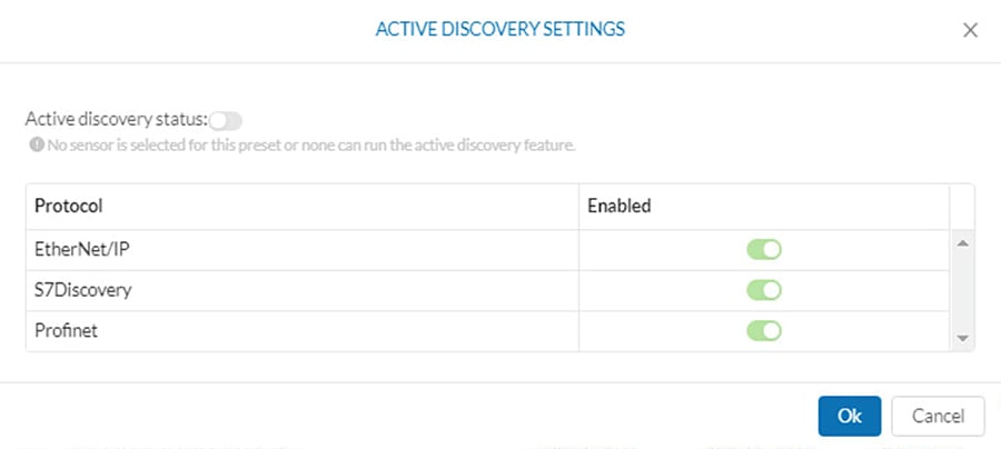
■![]() Active discovery can be enabled and disabled in a sensor. When enabled, discovery jobs are launched every 10 minutes for selected protocols. Active discovery can be disabled completely or per protocol when not needed.
Active discovery can be enabled and disabled in a sensor. When enabled, discovery jobs are launched every 10 minutes for selected protocols. Active discovery can be disabled completely or per protocol when not needed.
■![]() During installation, there is an option to select active discovery. If you plan to use active discovery functionality, make sure to select it during installation. Once the sensor is installed, active discovery can be turned on and off as required.
During installation, there is an option to select active discovery. If you plan to use active discovery functionality, make sure to select it during installation. Once the sensor is installed, active discovery can be turned on and off as required.
■![]() The sensor needs to be configured with an IP address in the subnet that needs to be discovered. It may use the sensor IP. There are no required configurations for active discovery on the switch running the Cisco Cyber Vision sensor application.
The sensor needs to be configured with an IP address in the subnet that needs to be discovered. It may use the sensor IP. There are no required configurations for active discovery on the switch running the Cisco Cyber Vision sensor application.
■![]() A sensor can perform active discovery in different subnets. In this case, it needs an IP address in each subnet.
A sensor can perform active discovery in different subnets. In this case, it needs an IP address in each subnet.
■![]() Active discovery supports three broadcast protocols: EtherNet/IP (Rockwell), Profinet, and S7 (Siemens).
Active discovery supports three broadcast protocols: EtherNet/IP (Rockwell), Profinet, and S7 (Siemens).
■![]() Active discovery is enabled on selected presets
Active discovery is enabled on selected presets
Note: Active discovery was validated only on sensors running on IE3400 and IE3300 10G. When enabling on hardware sensor, IC3000 must have an interface connected to the network in which active discovery is needed.
Figure 14 Active Discovery Preset
Performance
The control system engineer deploying a hardware or network sensor must consider its performance numbers. The critical performance metrics for Cyber Vision Version are:
■![]() The number of flows supported for a single Cisco IC3000 is 12,000 packets per second or 135 Mbps.
The number of flows supported for a single Cisco IC3000 is 12,000 packets per second or 135 Mbps.
■![]() The sensor on the Catalyst IE3400 can support approximately 9,600 packets per second or 105 Mbps.
The sensor on the Catalyst IE3400 can support approximately 9,600 packets per second or 105 Mbps.
■![]() The sensor on the Catalyst 9300 can support approximately 30,000 packets per second or 340 Mbps.
The sensor on the Catalyst 9300 can support approximately 30,000 packets per second or 340 Mbps.
Note: The standard MTU of 1500 was used to calculate performance in Mbps.
Note: These performance metrics apply to Cisco Cyber Vision release 3.1.0
Discover Use Cases
The following use cases are enabled by Cisco Cyber Vision on Industrial Security Design.
Discovery of OT/IT Assets and Flows
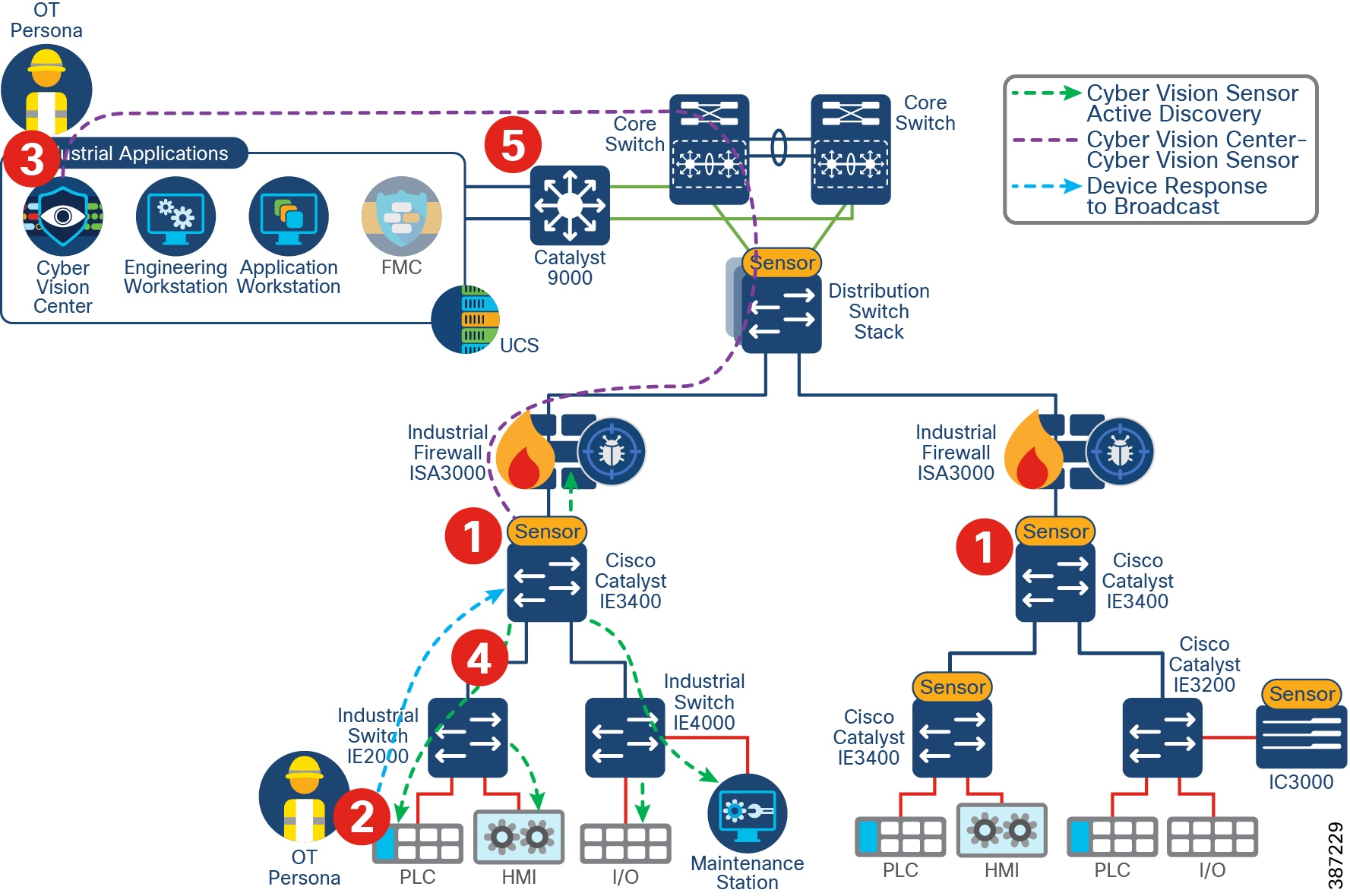
Discovering industrial and IT assets are key for creating an up-to-date asset inventory. The inventory should also contain important metadata about those assets like IP addresses, MAC addresses, operating system version, patch levels, assigned hostname, and so on. It is also important to discover application flows between those assets. These application flows include the flow of information between IACS products. Discovery of IT/OT Assets and Flows shows steps for discovery of assets and flows using passive discovery.
1.![]() A sensor is deployed in the Cell/Area Zone.
A sensor is deployed in the Cell/Area Zone.
2.![]() A device is introduced in the Cell/Area Zone.
A device is introduced in the Cell/Area Zone.
Note: Steps 1 and 2 can be reversed for brownfield deployments where the sensor is introduced in an existing network.
3.![]() The device starts communicating and flows are captured by sensors in the path.
The device starts communicating and flows are captured by sensors in the path.
4.![]() The Sensor sends metadata about devices and flows to Cisco Cyber Vision Center. Device, flows, vulnerabilities, and events are shown on the GUI.
The Sensor sends metadata about devices and flows to Cisco Cyber Vision Center. Device, flows, vulnerabilities, and events are shown on the GUI.
5.![]() (Optional) Information is sent from Cisco Cyber Vision Center in the Industrial Zone to the Cisco Cyber Vision Global Center in the Enterprise Zone.
(Optional) Information is sent from Cisco Cyber Vision Center in the Industrial Zone to the Cisco Cyber Vision Global Center in the Enterprise Zone.
Figure 15 Discovery of IT/OT Assets and Flows

Asset Visibility Across Multiple Plants
As shown in Discovery of IT/OT Assets and Flows Step 5, components, events, vulnerabilities, and flows are sent to Cisco Cyber Vision Global Center. An engineer supporting multiple factories will have a single view of all the assets in all the factories and the relevant metadata. Local plant OT engineers are able to use the Cisco Cyber Vision Center within their own plant.
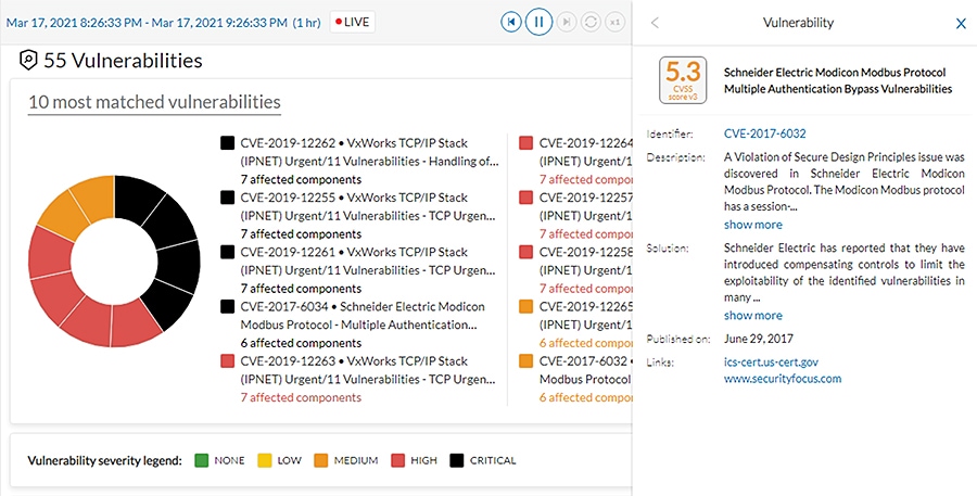
Discovery of Asset with a Known Vulnerability and Recommend Fix
After asset discovery, if an asset matches a vulnerability in the KDB, Cisco Cyber Vision Center will alert and recommend a fix.
Figure 16 Vulnerabilities on Component
Discovery of New Threats
The Cisco Cyber Vision KDB is updated frequently to include new discovered threats. After upgrade, if any component matches a new rule, the component will show the new vulnerability and suggested action.
Active Discovery of OT Devices in a Subnet
Active discovery may be used to expedite discovery of components, get additional details on assets, or discover silent devices. Active Discovery of Devices shows the steps involved in active discovery.
1.![]() A sensor is deployed in the network.
A sensor is deployed in the network.
2.![]() A device is connected to the network (Steps 1 and 2 could occur in any order).
A device is connected to the network (Steps 1 and 2 could occur in any order).
3.![]() A Preset is created in Cisco Cyber Vision Center and active discovery is enabled for desired protocol.
A Preset is created in Cisco Cyber Vision Center and active discovery is enabled for desired protocol.
4.![]() The Sensor sends broadcast to devices.
The Sensor sends broadcast to devices.
5.![]() The Sensor captures responses from devices and sends information to Cisco Cyber Vision Center.
The Sensor captures responses from devices and sends information to Cisco Cyber Vision Center.
Figure 17 Active Discovery of Devices
Segment
Segmentation is a key component to creating zones of trust to help protect IACS networks and processes. IEC 62443 details restricted data flow recommendations to segment the control system into zones and conduits to limit the unnecessary flow of data between process networks or services, where unintentional or accidental cross-pollination of traffic between untrusted entities must be restricted. The Industrial Security solution provides basic logical isolation guidance for segmenting the Cell/Area Zone traffic.
Some plants may segment the networks into physically separate networks based on risk. For example, plants may provide a physically separate, dedicated network for non-operational multiservice type applications such as voice services within the plant. VLAN segmentation is the traditional approach that has been adopted to creating segmentation across the Cell/Area Zone. The VLAN will be defined for a group of devices that need to communicate with each other within the Layer 2 domain or subnet. Typically, a boundary device such as a Layer 3 router, switch, or firewall is needed to connect the VLAN into the larger production network.
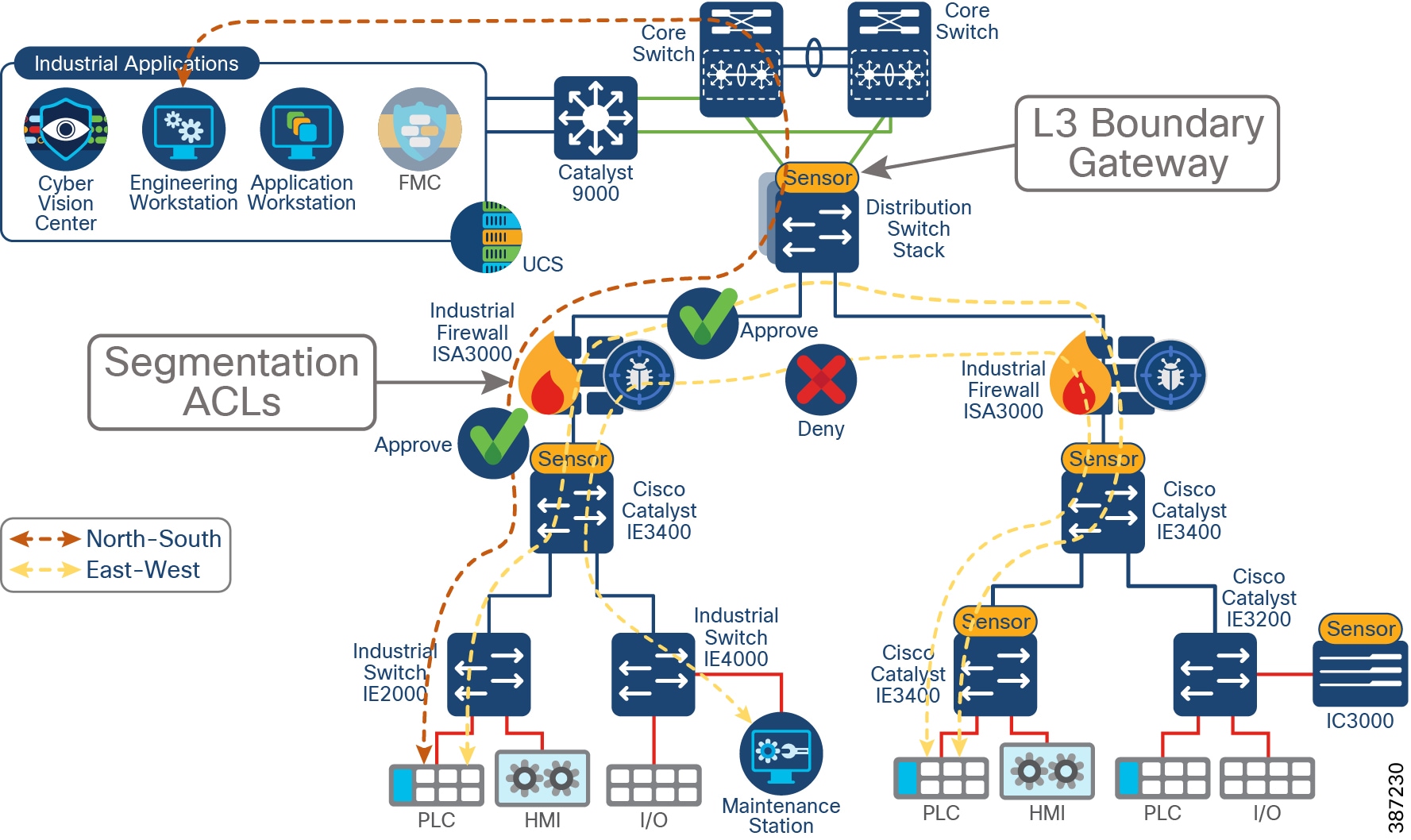
In the industrial Automation design, it is recommended to at least separate management and data traffic, such as IACS, into different VLANs; this separation has the advantage of keeping the network device reachability independent of any issues that may be occurring in the IACS network. The Layer 3 boundary and gateway for devices is in the distribution switch as shown in Segmentation on Industrial Foundation Security. Industrial security design enhances basic VLAN segmentation by creating access control lists (ACLs) to allow or deny communications outside of the VLAN to provide inter-cell/area communication such as controller-to-controller communication or controller-to-IACS applications. ACLs can be implemented on a firewall or at the Layer 3 boundary.
The Foundation Industrial Security design builds upon VLAN segmentation to limit and contain security incidents within a zone. To achieve that objective, a Cisco ISA 3000 is deployed in the Cell/Area Zone as shown in Segmentation on Industrial Foundation Security. ACLs can be configured on the firewall as well as intrusion prevention capabilities. The configuration, including ACLs and policies, is managed by Cisco FMC. The ISA3000 can also include Cisco AMP to provide protection against malware and deep-packet inspection for intrusion detection and protection.
As discussed in this design, segmentation through ACLs implemented on the ISA 3000 achieves the goal of providing granular flow access control. Nevertheless, when creating ACLs based on IPs and subnets, it requires a static configuration and it needs to be maintained as the network changes. For a simplified way to segment, full spectrum security uses TrustSec to provide dynamic segmentation.
Figure 18 Segmentation on Industrial Foundation Security
The segmentation section of this document covers the following topics:
■![]() Cisco ISA 3000 Firewall—Introduces ISA 3000 and FTD as its software. It provides some context to understand packet flow on FTD and the difference between firewall functionality (used for segmentation) and intrusion prevention (used in Detect and Respond). It also introduces SCADA preprocessors on FTD.
Cisco ISA 3000 Firewall—Introduces ISA 3000 and FTD as its software. It provides some context to understand packet flow on FTD and the difference between firewall functionality (used for segmentation) and intrusion prevention (used in Detect and Respond). It also introduces SCADA preprocessors on FTD.
■![]() FTD Management—Briefly mentions FTD management options and dives deeper into FMC as the recommended manager for ISA 3000.
FTD Management—Briefly mentions FTD management options and dives deeper into FMC as the recommended manager for ISA 3000.
■![]() FTD Deployment Modes— Explains how ISA 3000 can be deployed in router and transparent mode and what interface options are available for each.
FTD Deployment Modes— Explains how ISA 3000 can be deployed in router and transparent mode and what interface options are available for each.
■![]() Design Considerations—This subsection starts by naming key design considerations to select a deployment/interface mode for the ISA 3000. Then it explains high availability options as validated. It also provides deployment options for FMC and considerations on management interfaces and licensing for FMC and ISA 3000. Finally, since ACLs are used for segmentation in this CVD, it provides an overview, best practices on access control lists, and guidance (with an example) on ACLs that can be implemented to protect a Cell/Area Zone.
Design Considerations—This subsection starts by naming key design considerations to select a deployment/interface mode for the ISA 3000. Then it explains high availability options as validated. It also provides deployment options for FMC and considerations on management interfaces and licensing for FMC and ISA 3000. Finally, since ACLs are used for segmentation in this CVD, it provides an overview, best practices on access control lists, and guidance (with an example) on ACLs that can be implemented to protect a Cell/Area Zone.
■![]() Segment Use Cases—Showcases segmentation use cases with ISA3000 Firepower Threat Defense.
Segment Use Cases—Showcases segmentation use cases with ISA3000 Firepower Threat Defense.
Cisco ISA 3000 Firewall
Cisco ISA 3000 is an industrial firewall that conforms to specifications for industrial automation environments and provides OT-targeted protection based on proven enterprise class security. This firewall is ideal for IACS applications where trusted zone segmentation is required. It provides the anchor point for converging IT and OT security visibility without interfering with industrial operational practice. Manufacturers can improve security and gain visibility with the firewall’s DPI and IDS/IPS abilities to track OT application behavior for industrial protocols such as the Common Industrial Protocol (CIP), Profinet and Modbus/TCP, abnormal traffic patterns, and malicious attacks.
The ISA 3000 hardware can run either Adaptive Security Appliance (ASA) or Firepower Threat Defense (FTD) software.
■![]() ASA is a traditional, advanced stateful firewall and VPN concentrator.
ASA is a traditional, advanced stateful firewall and VPN concentrator.
■![]() FTD, also known as Firepower Next-Generation Firewall (NGFW), combines an advanced stateful firewall, VPN concentrator, and next generation IPS. In other words, the FTD takes the best of ASA functionality and combines it with the best next-generation firewall and IPS functionality.
FTD, also known as Firepower Next-Generation Firewall (NGFW), combines an advanced stateful firewall, VPN concentrator, and next generation IPS. In other words, the FTD takes the best of ASA functionality and combines it with the best next-generation firewall and IPS functionality.
We recommend using the FTD version over the ASA because it contains most of the major functionality of the ASA and is the focus of next generation firewall and IPS functionality. The Industrial Security Design tested and validated the FTD version.
Note: Switching between ASA and FTD requires you to reimage the device. Cisco provides ASA-to-FTD migration tools to help you convert your ASA to an FTD.
ISA 3000 supports the following high availability options:
■![]() Hardware bypass allows traffic flow through the firewall device in case of failure, guaranteeing continuity of operations in critical Industrial operation environments
Hardware bypass allows traffic flow through the firewall device in case of failure, guaranteeing continuity of operations in critical Industrial operation environments
–![]() It is available on copper interfaces and must be enabled on interface pairs:
It is available on copper interfaces and must be enabled on interface pairs:
—On ISA3000-2C2F: between G1/1 and G1/2
—On ISA3000-4C: between G1/1 and G1/2, or/and G1/3 and G1/4
■![]() High Availability (Active/Standby Failover) allows ISA3000 to failover to a standby unit in case of device or communication failure. The following is required for high availability:
High Availability (Active/Standby Failover) allows ISA3000 to failover to a standby unit in case of device or communication failure. The following is required for high availability:
–![]() Each unit requires a license for high availability.
Each unit requires a license for high availability.
–![]() The two units in a High Availability configuration must be the same model, license, firewall mode, and software version.
The two units in a High Availability configuration must be the same model, license, firewall mode, and software version.
–![]() Both firewalls should be in the same domain or group on the FMC, be fully deployed on the FMC with no uncommitted changes.
Both firewalls should be in the same domain or group on the FMC, be fully deployed on the FMC with no uncommitted changes.
–![]() Have the same Network Time Protocol (NTP) configuration.
Have the same Network Time Protocol (NTP) configuration.
Note: When deploying Active/Standby do not use hardware bypass. A hardware failure should cause a switchover instead.
To obtain more information about the Cisco ISA3000 see:
https://www.cisco.com/c/en/us/products/collateral/security/industrial-security-appliance-3000/data-sheet-c78-735839.html#Yourruggedizedchoiceforindustrialfirewalldeployments
Firepower Threat Defense
FTD is a converged software image that contains ASA firewall capabilities with Firepower services. FTD has two main engines:
■![]() Linux over ASA (LINA) provides firewall functionality such as access control rules.
Linux over ASA (LINA) provides firewall functionality such as access control rules.
■![]() Snort, an open source next-generation intrusion prevention system (NGIPS), that provides enhanced security against even the most sophisticated threats to help organizations comply with regulatory requirements. It provides intrusion prevention capabilities.
Snort, an open source next-generation intrusion prevention system (NGIPS), that provides enhanced security against even the most sophisticated threats to help organizations comply with regulatory requirements. It provides intrusion prevention capabilities.
When a packet enters the ingress interface it is handled by the LINA engine. If the policy requires, the packet is inspected by the Snort engine (mainly Layer 7 inspection). The Snort engine returns a verdict (allowed or blocked) for the packet and the LINA engine drops or forwards the packet based on Snort’s verdict.
FTD Packet Path shows the actual path of the packet as it traverses through FTD. Understanding the packet flow is key to design optimal traffic policies. Traffic that needs to be either blocked or unconditionally trusted can be handled entirely in hardware, limiting the number of packets that need extra processing. Best practices for rule design will be covered in Access Control Rules Concepts.
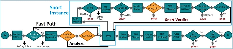
FTD provides intrusion prevention system (IPS) capabilities by inspecting traffic going through the network and warning or potentially blocking flows that are detected as malicious. IPS devices are usually placed in the traffic path so that the traffic can be blocked before reaching its destination. For more information on FTD packet processing see:
https://www.cisco.com/c/dam/en/us/td/docs/security/firepower/Self-Help/NGFW_Policy_Order_of_Operations.pdf.
FTD Preprocessors
In order to prepare traffic for inspection, FTD uses preprocessors to normalize traffic and identify protocol anomalies. Preprocessors can generate events when packets trigger specific preprocessor options configured. There is a default policy in FTD called the Network Analysis Policy that enables certain preprocessors by default; see Network Analysis Policy.
This guide explores supervisory control and data acquisition (SCADA) preprocessors further, given their importance in industrial information environments. For additional details on other preprocessors, refer to the FMC configuration guide at:
https://www.cisco.com/c/en/us/support/security/defense-center/products-installation-and-configuration-guides-list.html.
SCADA Preprocessors
SCADA protocols monitor, control, and acquire data from industrial, infrastructure, and facility processes such as manufacturing, production, water treatment, electric power distribution, airport and shipping systems, and so on. The Firepower system provides the following SCADA preprocessors:
■![]() Modbus preprocessor—The Modbus protocol, which was first published in 1979 by Modicon, is a widely used SCADA protocol. The Modbus preprocessor detects anomalies in Modbus traffic and decodes the Modbus protocol for processing by the rules engine, which uses Modbus keywords to access certain protocol fields.
Modbus preprocessor—The Modbus protocol, which was first published in 1979 by Modicon, is a widely used SCADA protocol. The Modbus preprocessor detects anomalies in Modbus traffic and decodes the Modbus protocol for processing by the rules engine, which uses Modbus keywords to access certain protocol fields.
■![]() DNP3 preprocessor—The Distributed Network Protocol (DNP3) is a SCADA protocol that was originally developed to provide consistent communication between electrical stations. DNP3 has also become widely used in the water, waste, transportation, and many other industries. The DNP3 preprocessor detects anomalies in DNP3 traffic and decodes the DNP3 protocol for processing by the rules engine, which uses DNP3 keywords to access certain protocol fields.
DNP3 preprocessor—The Distributed Network Protocol (DNP3) is a SCADA protocol that was originally developed to provide consistent communication between electrical stations. DNP3 has also become widely used in the water, waste, transportation, and many other industries. The DNP3 preprocessor detects anomalies in DNP3 traffic and decodes the DNP3 protocol for processing by the rules engine, which uses DNP3 keywords to access certain protocol fields.
■![]() CIP preprocessor—The Common Industrial Protocol (CIP) is a widely used application protocol that supports industrial automation applications. EtherNet/IP (ENIP) is an implementation of CIP that is used on Ethernet-based networks. The CIP preprocessor detects CIP and ENIP traffic running on TCP or UDP and sends it to the intrusion rules engine. You can use CIP and ENIP keywords in custom intrusion rules to detect attacks in CIP and ENIP traffic.
CIP preprocessor—The Common Industrial Protocol (CIP) is a widely used application protocol that supports industrial automation applications. EtherNet/IP (ENIP) is an implementation of CIP that is used on Ethernet-based networks. The CIP preprocessor detects CIP and ENIP traffic running on TCP or UDP and sends it to the intrusion rules engine. You can use CIP and ENIP keywords in custom intrusion rules to detect attacks in CIP and ENIP traffic.
■![]() S7Commplus—The S7 Comm Plus is a proprietary protocol developed by Siemens. The S7Commplu preprocessor detects S7Commplus traffic. You can use S7Commplus keywords in custom intrusion rules to detect attacks in S7Commplus traffic.
S7Commplus—The S7 Comm Plus is a proprietary protocol developed by Siemens. The S7Commplu preprocessor detects S7Commplus traffic. You can use S7Commplus keywords in custom intrusion rules to detect attacks in S7Commplus traffic.
FTD Management
Managing ISA 3000 running FTD can be done with multiple managers as described in:
https://www.cisco.com/c/en/us/td/docs/security/firepower/quick_start/isa3000/isa-3000-gsg/m_introduction.html.
FMC and Firepower Device Manager are on-premises, web-based options. FDM is a simplified on-device manager while FMC is a feature rich multi-device manager option. The Foundation Industrial Security recommends using FMC multi-site capabilities to simplify deployment of consistent policies for several devices and to take advantage of the FTD feature set. FMC also provides powerful analysis and monitoring of traffic and events.
Note: FMC is not compatible with other managers because the FMC owns the FTD configuration and you are not allowed to configure the FTD directly, bypassing the FMC. In order to change managers a configuration reset is required.
Note: CLI configuration is not supported on FTD but CLI commands can be used for diagnostic and advanced troubleshooting and debugging.
Firepower Manager Center
The Cisco Firepower Management Center is the administrative nerve center for select Cisco security products (for example, the ISA 3000 Firewall or a commercial grade Firepower-FPR for the iDMZ) running on a number of different platforms. It provides complete and unified management of firewalls, application control, intrusion prevention, URL filtering, and advanced malware protection. The Management Center is the centralized point for event and policy management.
The FMC provides extensive intelligence about the users, applications, devices, threats, and vulnerabilities that exist in your network. It also uses this information to analyze your network’s vulnerabilities. It then provides tailored recommendations on what security policies to put in place and what security events you should investigate.
The Management Center provides easy-to-use policy screens to control access and guard against known attacks. It integrates with advanced malware protection and sandboxing technology and it provides tools to track malware infections throughout your network.
FMC integrates the Cisco Talos Intelligence Group’s security, threat, and vulnerability intelligence for up-to-the-minute threat protection. Advanced threat intelligence (Talos) is the threat intelligence organization at the center of the Cisco security portfolio. Internet connectivity is required for updates. For networks with restricted access to the internet, you can configure a proxy server. For more information see: https://talosintelligence.com/about.
■![]() Consistent and scalable configuration of firewall access, application control, threat prevention, URL filtering, and advanced malware protection settings in a single policy.
Consistent and scalable configuration of firewall access, application control, threat prevention, URL filtering, and advanced malware protection settings in a single policy.
■![]() Eases policy administration, reduces errors, and promotes consistency.
Eases policy administration, reduces errors, and promotes consistency.
■![]() Enables a single policy to be deployed to multiple security solutions.
Enables a single policy to be deployed to multiple security solutions.
■![]() Application visibility further reduces threats to your network with precise control of more than 4,000 commercial applications traversing managed firewalls.
Application visibility further reduces threats to your network with precise control of more than 4,000 commercial applications traversing managed firewalls.
■![]() Uses the open-source standard Open App ID for detailed identification and control over custom applications.
Uses the open-source standard Open App ID for detailed identification and control over custom applications.
■![]() Provides the visibility you need through customizable dashboards with custom and template-based reports.
Provides the visibility you need through customizable dashboards with custom and template-based reports.
■![]() Delivers comprehensive alerts and reports for both general and focused information.
Delivers comprehensive alerts and reports for both general and focused information.
■![]() Displays event and contextual information in hyperlinked tables, graphs, and charts for easy-to-use analysis.
Displays event and contextual information in hyperlinked tables, graphs, and charts for easy-to-use analysis.
■![]() Monitors network behavior and performance to identify anomalies and maintain system health.
Monitors network behavior and performance to identify anomalies and maintain system health.
The Cisco Firepower Management Center provides unified management across the entire “attack continuum”—before, during, and after an attack.
■![]() Before—Provides visibility into what is running in your network, creates firewall rules, and controls how more than 4,000 commercial and custom applications are used in your environment.
Before—Provides visibility into what is running in your network, creates firewall rules, and controls how more than 4,000 commercial and custom applications are used in your environment.
■![]() During—Defines the intrusion prevention levels, URL reputation rules, and advanced malware protection pieces to be put in place and applies policies.
During—Defines the intrusion prevention levels, URL reputation rules, and advanced malware protection pieces to be put in place and applies policies.
■![]() After—Generates a graphical representation of all the devices the attack has infected, provides the ability to easily create a custom rule to stop the attack from advancing, and gives a detailed analysis of the malware to safely remediate.
After—Generates a graphical representation of all the devices the attack has infected, provides the ability to easily create a custom rule to stop the attack from advancing, and gives a detailed analysis of the malware to safely remediate.
FTD Deployment Modes
FTD provides two deployment modes and six interface modes that are discussed in this section.
■![]() Routed—The FTD device is considered to be a router hop in the network. Each physical interface that you want to route between is on a different subnet.
Routed—The FTD device is considered to be a router hop in the network. Each physical interface that you want to route between is on a different subnet.
■![]() Transparent—The FTD device is a Layer 2 firewall that acts like a “bump in the wire” or a “stealth firewall” and is not seen as a router hop to connected devices. However, like any other firewall, access control between interfaces is controlled and all of the usual firewall checks are in place.
Transparent—The FTD device is a Layer 2 firewall that acts like a “bump in the wire” or a “stealth firewall” and is not seen as a router hop to connected devices. However, like any other firewall, access control between interfaces is controlled and all of the usual firewall checks are in place.
Note: A firewall can be configured in a single deployment mode.
The following interface modes are available on FTD. Deployment and Interface Mode shows what interface modes are available per deployment mode.
■![]() Routed—Each interface that you want to route between contains a different set of subnets and can be used on routed deployment mode only. All firewall functions are available.
Routed—Each interface that you want to route between contains a different set of subnets and can be used on routed deployment mode only. All firewall functions are available.
■![]() Switched (BVI)—Multiple interfaces can be grouped on a bridge group. Each bridge group includes a Bridge Virtual Interface (BVI) to which you assign an IP address on the network. When used in transparent mode, each bridge group is separate and cannot communicate with each other. All firewall functions are available.
Switched (BVI)—Multiple interfaces can be grouped on a bridge group. Each bridge group includes a Bridge Virtual Interface (BVI) to which you assign an IP address on the network. When used in transparent mode, each bridge group is separate and cannot communicate with each other. All firewall functions are available.
■![]() Inline Pair—Is an IPS mode interface. In an inline IPS deployment, you configure the Firepower system transparently on a network segment by binding two ports together. This allows the system to be installed in any network environment without the configuration of adjacent network devices. Inline interfaces receive all traffic unconditionally, but all traffic received on these interfaces is retransmitted out of an inline set unless explicitly dropped. This mode does not provide all firewall checks, but it provides all intrusion prevention system functionality. NAT, routing, and Layer 3 and Layer 4 stateful ACLs are not available.
Inline Pair—Is an IPS mode interface. In an inline IPS deployment, you configure the Firepower system transparently on a network segment by binding two ports together. This allows the system to be installed in any network environment without the configuration of adjacent network devices. Inline interfaces receive all traffic unconditionally, but all traffic received on these interfaces is retransmitted out of an inline set unless explicitly dropped. This mode does not provide all firewall checks, but it provides all intrusion prevention system functionality. NAT, routing, and Layer 3 and Layer 4 stateful ACLs are not available.
■![]() Inline Pair with Tap—In this case FTD is deployed inline, but the network traffic flow is undisturbed. Instead, the FTD makes a copy of each packet for analysis on the firewall. Note that intrusion events are still generated in this mode, and the table view of intrusion events indicates that the triggering packets would have been dropped in an Inline Pair deployment. This mode can be used as a transition step while you tune IPS rules before deploying fully inline.
Inline Pair with Tap—In this case FTD is deployed inline, but the network traffic flow is undisturbed. Instead, the FTD makes a copy of each packet for analysis on the firewall. Note that intrusion events are still generated in this mode, and the table view of intrusion events indicates that the triggering packets would have been dropped in an Inline Pair deployment. This mode can be used as a transition step while you tune IPS rules before deploying fully inline.
■![]() Passive—Passive interfaces monitor traffic flowing across a network using a switch SPAN or mirror port. The SPAN or mirror port allows for traffic to be copied from other ports on the switch. This function provides the system visibility within the network without being in the flow of network traffic. When you configure the FTD in a passive deployment, the FTD cannot take certain actions such as blocking or shaping traffic.
Passive—Passive interfaces monitor traffic flowing across a network using a switch SPAN or mirror port. The SPAN or mirror port allows for traffic to be copied from other ports on the switch. This function provides the system visibility within the network without being in the flow of network traffic. When you configure the FTD in a passive deployment, the FTD cannot take certain actions such as blocking or shaping traffic.
■![]() Passive (ERSPAN)—Encapsulated remote switched port analyzer (ERSPAN) interfaces are passive interfaces that allow you to monitor traffic from source ports distributed over multiple switches and uses GRE to encapsulate the traffic. ERSPAN interfaces are only allowed when the FTD is in routed firewall mode.
Passive (ERSPAN)—Encapsulated remote switched port analyzer (ERSPAN) interfaces are passive interfaces that allow you to monitor traffic from source ports distributed over multiple switches and uses GRE to encapsulate the traffic. ERSPAN interfaces are only allowed when the FTD is in routed firewall mode.
Note: You can mix interface modes on a single FTD appliance.
Deployment and Interface Mode shows available interface and deployment mode combinations. It also shows which combinations have partial versus full LINA-engine capabilities and what options allow for dropping traffic as a result of inspection.
Note: Unsupported firewall features on IPS interfaces (Inline and Passive interfaces) are DHCP server, DHCP relay, DHCP client, TCP intercept, routing, NAT, VPN, application inspection, QoS, NetFlow, and VXLAN.
Note: Hardware bypass is only recommended on transparent deployment mode.
Design Considerations
The next section covers the design considerations that must be considered by OT control system engineers and IT security architects when deploying Industrial Automation Network Security solutions. The design considerations are important to understand how segmentation works, the different possible approaches, and the rationale for choosing a particular approach for this design.
The following is a list of requirements and questions to consider when choosing a network design:
■![]() Segmentation requirements—Where should they be placed to achieve desired segmentation?
Segmentation requirements—Where should they be placed to achieve desired segmentation?
■![]() Ability to block traffic per segmentation rules or when an intrusion is detected
Ability to block traffic per segmentation rules or when an intrusion is detected
■![]() Network role—Route (Layer 3) or Switch (Layer 2)—Desired role of the firewall in the network. Is it expected that the firewall performs NAT or Layer 3 functions?
Network role—Route (Layer 3) or Switch (Layer 2)—Desired role of the firewall in the network. Is it expected that the firewall performs NAT or Layer 3 functions?
■![]() High availability—Minimize downtime because of software or hardware failures.
High availability—Minimize downtime because of software or hardware failures.
■![]() Neighbor impact—Insertion onto existing deployments may require reconfiguration of neighbor devices.
Neighbor impact—Insertion onto existing deployments may require reconfiguration of neighbor devices.
■![]() Network requirements, such as trunk or ether-channel support.
Network requirements, such as trunk or ether-channel support.
The reminder of this section describes how these requirements should guide you to select the right deployment mode for your environment.
The first question in the list (what are the segmentation requirements?) is critical to decide the location in the network. If the firewall is needed to block traffic between Cell/Area Zones, it needs to be placed at the exit point of the zone so it can analyze all incoming and outgoing flows. If the objective is to protect a specific device or line of devices, it should be placed between the switch and the device that is protecting. Inn this document, a firewall is used for inter-zone segmentation; by placing the firewall between the distribution switch and the Cell/Area Zone it is protecting, the design achieves the segmentation goal without interfering with Cell/Area Zone internal traffic.
Considerations about the ability to drop traffic will determine what interface type could be used. Deployment and Interface Mode provides a list of interfaces modes that can drop traffic. Passive interfaces or inline with tap provide intrusion detection capabilities but not the ability to block traffic.
When evaluating the desired role in the network, consider what firewall features are important for your deployment. For example, on an iDMZ firewall, VPN is required to provide secure connectivity to the industrial zone. In some scenarios NAT may be required on the firewall. The description column in Deployment and Interface Mode provides a list of what interface deployment types are needed for full firewall functionality.
It is also important to consider what is the firewall insertion process into the network. If the firewall is being deployed in a brownfield environment, some modes could require reconfiguration of neighbor devices. That is the case when deploying a routed firewall, since the firewall will become the Layer 3 boundary. In a Cell/Area Zone, where the Layer 3 boundary is provided by the distribution switch, a transparent firewall could be installed without redesigning the network. In addition, if a switched interface mode on a transparent firewall is chosen, it may require some configuration changes in neighbor devices as explained in FTD Interface Mode BVI Limitations for Trunk Links.
Finally, there are two options for high availability: hardware bypass and active/standby mode. Hardware bypass is only recommended on transparent mode. The reason for that is that when there is a failure, the firewall cannot perform any routing functionality. When hardware bypass is used there is no traffic interruption, but traffic is not inspected.
Note: When transparent mode uses switched interface, hardware bypass can be used only on access links (not supported in trunks) as explained in FTD Interface Mode BVI Limitations for Trunk Links. As a result, hardware bypass for trunks is only supported on Transparent mode configurations with interface mode inline pair.
The second option for high availability is active/standby mode. That is supported on transparent and routed mode but requires dual hardware.
FTD Interface Mode Decision Process shows an example of the decision process followed in this design guide. A similar process needs to be followed with the key requirements of the network. The decision process followed a discard approach in which deployment and interface modes that did not fit the requirements are not considered. At the end, transparent mode with inline interface is selected. For high availability, hardware bypass and active/standby are available options. If possible, deploy high availability to guarantee inspection even in failure scenarios, but if the number of firewalls and licenses are a constraint, consider the hardware bypass option.
Note: In the decision process in the example, feature functionality such as VPN and NAT was not considered since they are not key requirements of this design. VPN is provided at iDMZ and NAT could be provided on industrial switches.
Figure 20 FTD Interface Mode Decision Process
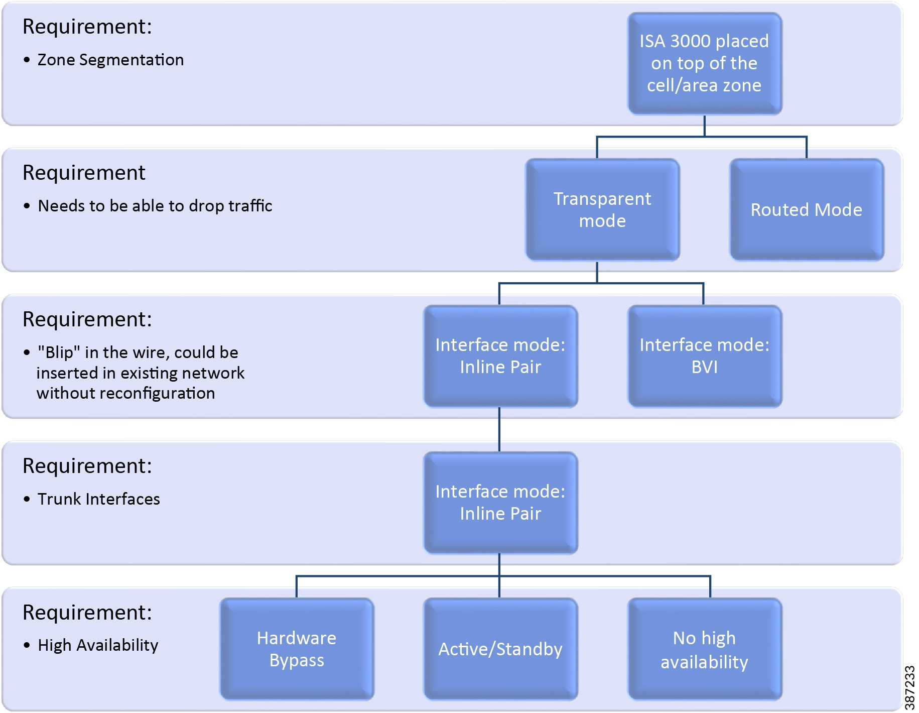
FTD Interface Mode BVI Limitations for Trunk Links
While BVI interfaces on ISA 3000 provide full firewall functionality, they require different VLAN numbers on inside and outside interfaces for a single subnet as shown in Transparent Mode with BVI Interface.
Figure 21 Transparent Mode with BVI Interface
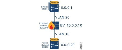
If using trunk ports, there are two limitations:
■![]() The hardware bypass feature is not supported on the stated scenario because VLAN tagging is different on the inside and outside interfaces.
The hardware bypass feature is not supported on the stated scenario because VLAN tagging is different on the inside and outside interfaces.
■![]() It creates complexity by requiring VLAN mapping. In order to insert ISA 3000 in the existing network, the VLAN configuration needs to be modified on one side of the firewall.
It creates complexity by requiring VLAN mapping. In order to insert ISA 3000 in the existing network, the VLAN configuration needs to be modified on one side of the firewall.
Given the limitations stated above, inline sets are chosen for the foundation industrial security design. FTD Interface Mode Decision Process illustrates the decision process.
Note: Inline sets are chosen as FTD interface mode in this design. It is important to understand that this provides partial LINA-engine checks. Some unsupported features are NAT and Stateful firewall. If Layer 2 NAT is required, it needs to be implemented on the switch downstream.
Single Node Deployment
For inline interface mode an inline set is created on FMC to bound the interfaces together. For the industrial security design, one interface goes to the distribution switch and the other interface goes to an aggregation switch in the Cell/Area Zone. Optionally, a second Cell/Area Zone can be added using the additional two ports on the ISA 3000 as depicted in Single ISA 3000 Node Deployment.
Figure 22 Single ISA 3000 Node Deployment
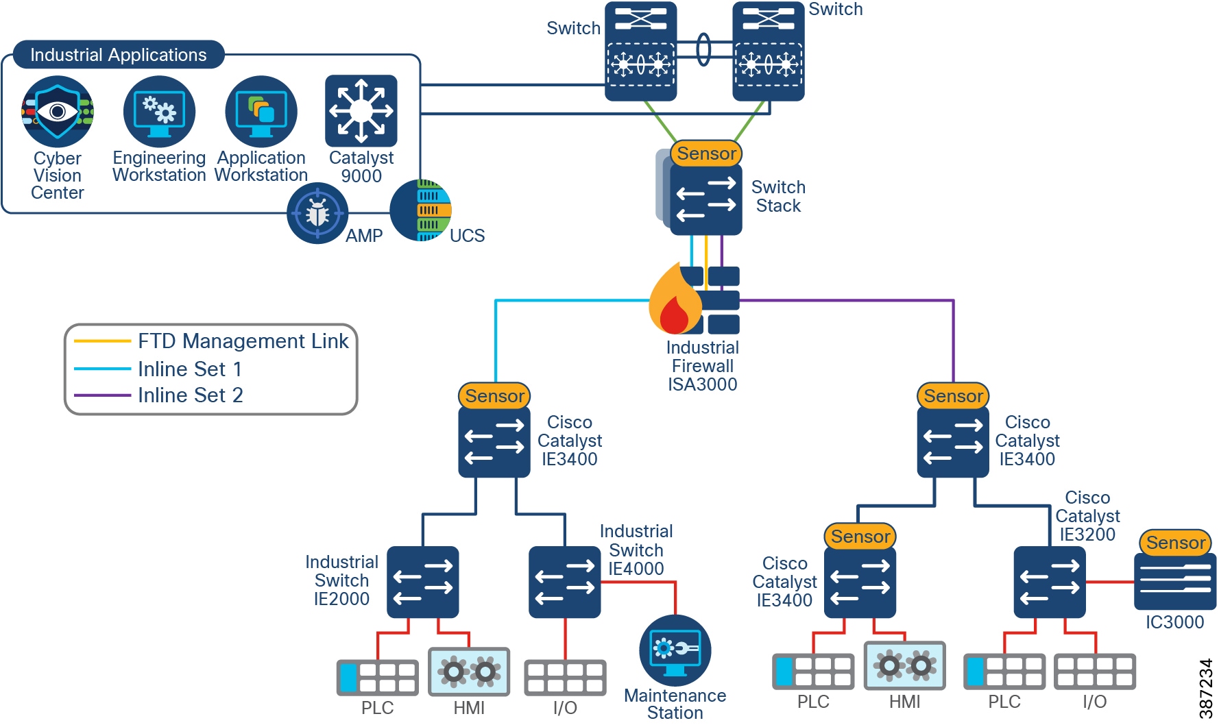
■![]() Inline sets should be paired in the following way: Gi1/1-Gi1/2 and Gi1/3-Gi1/4 for hardware bypass to connect the correct interfaces.
Inline sets should be paired in the following way: Gi1/1-Gi1/2 and Gi1/3-Gi1/4 for hardware bypass to connect the correct interfaces.
■![]() Before you can configure inline interface mode, you must configure inline sets and then assign a pair of inline interfaces to it. An inline set is a grouping of one or more inline interface pairs on a device; an inline interface pair can belong to only one inline set at a time. In this design an inline pair contains a single pair of interfaces as shown in Single ISA 3000 Node Deployment.
Before you can configure inline interface mode, you must configure inline sets and then assign a pair of inline interfaces to it. An inline set is a grouping of one or more inline interface pairs on a device; an inline interface pair can belong to only one inline set at a time. In this design an inline pair contains a single pair of interfaces as shown in Single ISA 3000 Node Deployment.
■![]() When creating the inline interface, select propagate link state to bring down the second interface in the inline interface pair when one of the interfaces in an inline set goes down.
When creating the inline interface, select propagate link state to bring down the second interface in the inline interface pair when one of the interfaces in an inline set goes down.
■![]() You can use the Snort Fail Open option to either drop traffic or allow traffic to pass without inspection when the Snort process is busy or down. Unchecking the option will drop the traffic that cannot be inspected. We recommend leaving fail open option enabled to guarantee traffic will flow even when Snort is down.
You can use the Snort Fail Open option to either drop traffic or allow traffic to pass without inspection when the Snort process is busy or down. Unchecking the option will drop the traffic that cannot be inspected. We recommend leaving fail open option enabled to guarantee traffic will flow even when Snort is down.
Active/Standby Node Deployment
Configuring high availability, also called failover, requires two identical Firepower Threat Defense devices connected to each other through a dedicated failover link and, optionally, a state link. Firepower Threat Defense supports Active/Standby failover, where one unit is the active unit and passes traffic. The standby unit does not actively pass traffic but synchronizes configuration and other state information from the active unit. When a failover occurs, the active unit fails over to the standby unit, which then becomes active.
The health of the active unit (hardware, interfaces, software, and environmental status) is monitored to determine if specific failover conditions are met. If those conditions are met, failover occurs.
The failover link is a dedicated connection between the two units to communicate the unit state, keep-alive messages, and configuration replication. The failover link can be connected directly or through an intermediate switch. ISA 3000 Active-Standby Deployment shows an active/standby ISA 3000 deployment with direct link. Each ISA 3000 is configured in transparent mode with two interfaces configured as an inline set pair.
Note that a single inline set is possible since ISA 3000 has four data interfaces and one needs to be dedicated to the failover link.
When the active unit fails over to the standby unit, the standby needs to detect the failure and switch over. In addition to that the topology is subject to spanning tree convergence. To minimize the downtime, it is possible to use rapid spanning tree (RSTP - IEEE 802.1w). During validation with RSTP outage was measured in the order of two to seven seconds. Note that in original traditional STP (IEEE 802.1D), it can take between 30-60s to unblock a trunk port after a change of topology.
Note: RSTP can lead to temporary flooding on topology change. It may also lead to small reconvergence on the Cell/Area Zone. For more information on RSTP refer to:
https://www.cisco.com/c/en/us/support/docs/lan-switching/spanning-tree-protocol/24062-146.html.
Figure 23 ISA 3000 Active-Standby Deployment
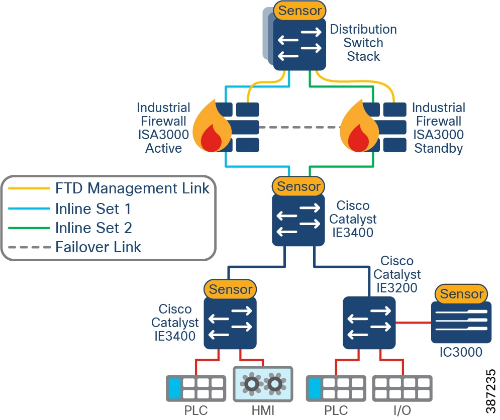
FMC Deployment Options
The Cisco FMC can be deployed as a physical or virtual appliance. Refer to the FMC data sheet to select an appliance that matches the scalability requirements of your environment:
https://www.cisco.com/c/en/us/products/collateral/security/firesight-management-center/datasheet-c78-736775.html?cachemode=refresh#Platformspecifications.
In the Foundation Industrial Security design FMC is located at the Enterprise Layer, enabling IT to manage the industrial firewalls from the Enterprise Zone. Communication between FMC and FTD uses TCP port 8305. See FMC to ISA Communication.
Note: It is possible to deploy FMC in the industrial zone, if Firewall management is considered critical to the plant operations. Note that disconnecting firewalls from FMC has no immediate impact to the Firewall operations, but limits monitoring and update capabilities. To deploy this option, make sure you understand FMC communication requirements. For more information see:
https://www.cisco.com/c/en/us/td/docs/security/firepower/670/configuration/guide/fpmc-config-guide-v67/security_internet_access_and_communication_ports.html.
Figure 24 FMC to ISA Communication
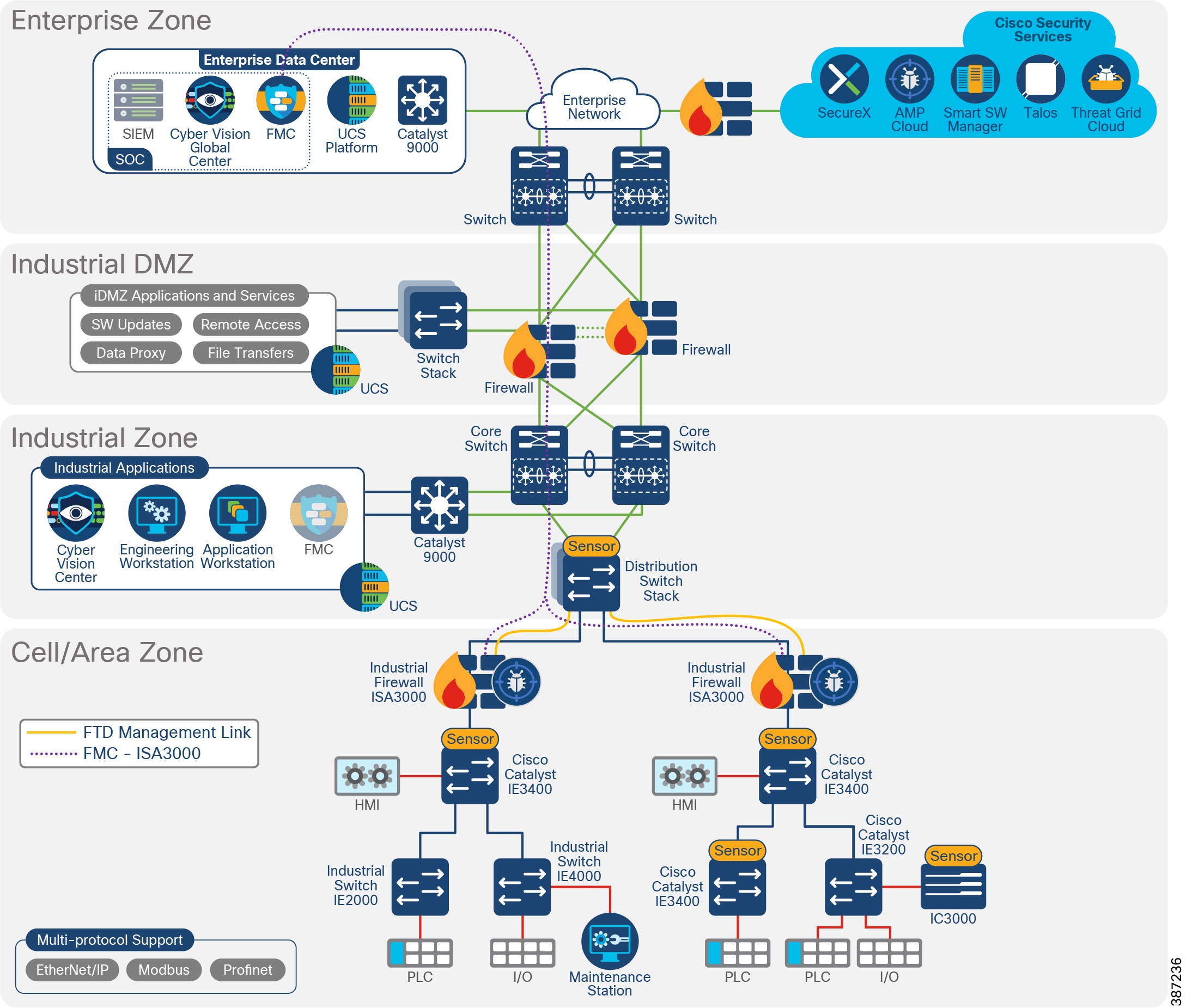
FMC Management Interfaces
The FMC uses the eth0 interface for initial setup, HTTP access for administrators, management of devices, as well as other management functions such as licensing and updates.
You can also configure additional management interfaces on the same network or on different networks. When the FMC manages large numbers of devices, adding more management interfaces can improve throughput and performance. For more information on management interface options refer to:
https://www.cisco.com/c/en/us/td/docs/security/firepower/misc/fmc-ftd-mgmt-nw/fmc-ftd-mgmt-nw.html#ID-2242-0000010c.
Cisco ISA 3000 Management Interfaces
Cisco ISA 3000 has a dedicated management interface used for management and event traffic; the internal name of this interface is br1.
In the Foundation Industrial Security design, the ISA 3000 management interface connects directly to the distribution switch using an access port. A VLAN is created exclusively to manage FTD devices. FMC to ISA Communication illustrates FMC to ISA3000 connectivity.
Note: On FTD it is possible to use data interfaces for management traffic. This option is not covered in this guide because it applies to the routed firewall option.
Cisco ISA 3000 Deployment Considerations
■![]() Having an inline firewall in the network adds latency. For applications requiring PTP, it is recommended to maintain flows within the network below the firewall because of the high-performance requirements of these types of applications.
Having an inline firewall in the network adds latency. For applications requiring PTP, it is recommended to maintain flows within the network below the firewall because of the high-performance requirements of these types of applications.
■![]() For deployments in which FMC and FTD devices are separated by a NAT device, use the option DONTRESOLVE when adding ISA 3000 to FMC. See:
For deployments in which FMC and FTD devices are separated by a NAT device, use the option DONTRESOLVE when adding ISA 3000 to FMC. See:
https://www.cisco.com/c/en/us/td/docs/security/firepower/670/configuration/guide/fpmc-config-guide-v67/device_management_basics.html?bookSearch=true.
■![]() Make sure ISA 3000 and FMC are time synchronized for a successful deployment. We recommend you configure all FTDs managed by an FMC to use the same NTP server as the FMC.
Make sure ISA 3000 and FMC are time synchronized for a successful deployment. We recommend you configure all FTDs managed by an FMC to use the same NTP server as the FMC.
■![]() When deploying Active/Standby do not use hardware bypass. A hardware failure should cause a switchover instead.
When deploying Active/Standby do not use hardware bypass. A hardware failure should cause a switchover instead.
■![]() Hardware bypass is only supported on copper interfaces. If you have a fiber Ethernet model, only the copper Ethernet pair (Gi1/1 and Gi1/2) supports hardware bypass.
Hardware bypass is only supported on copper interfaces. If you have a fiber Ethernet model, only the copper Ethernet pair (Gi1/1 and Gi1/2) supports hardware bypass.
■![]() If using hardware bypass, make sure all inline sets are grouped following the schema Gi1/1-Gi1/2 and Gi1/3-Gi1/4.
If using hardware bypass, make sure all inline sets are grouped following the schema Gi1/1-Gi1/2 and Gi1/3-Gi1/4.
■![]() When hardware bypass is active, traffic passes between these interface pairs at Layer 1. Both FDM and the FTD CLI will see the interfaces as being down. No firewall functions are in place, so make sure you understand the risks of allowing traffic to pass through the device.
When hardware bypass is active, traffic passes between these interface pairs at Layer 1. Both FDM and the FTD CLI will see the interfaces as being down. No firewall functions are in place, so make sure you understand the risks of allowing traffic to pass through the device.
■![]() Hardware bypass is enabled using FlexConfig. FlexConfig policy is a container of an ordered list of FlexConfig objects. It is used to allow configuring features not supported directly on FMC. You can use FlexConfig policy in FMC to specify the CLI to configure the feature.
Hardware bypass is enabled using FlexConfig. FlexConfig policy is a container of an ordered list of FlexConfig objects. It is used to allow configuring features not supported directly on FMC. You can use FlexConfig policy in FMC to specify the CLI to configure the feature.
■![]() When switching from normal operation to hardware bypass or from hardware bypass back to normal operation, traffic may be interrupted for some seconds. A number of factors can affect the length of the interruption, for example, copper port auto-negotiation and spanning tree protocol convergence. During this time, you may experience dropped connections.
When switching from normal operation to hardware bypass or from hardware bypass back to normal operation, traffic may be interrupted for some seconds. A number of factors can affect the length of the interruption, for example, copper port auto-negotiation and spanning tree protocol convergence. During this time, you may experience dropped connections.
Licensing
■![]() The base license for FTD comes with the ISA 3000 appliance; it enables networking, firewall and application visibility, and control.
The base license for FTD comes with the ISA 3000 appliance; it enables networking, firewall and application visibility, and control.
You can optionally purchase the following feature licenses:
–![]() Security Intelligence and Cisco Firepower Next-Generation IPS
Security Intelligence and Cisco Firepower Next-Generation IPS
–![]() Malware-Advanced Malware Protection for Networks (AMP)
Malware-Advanced Malware Protection for Networks (AMP)
■![]() All licenses are supplied to the FTD by the FMC. FTD does not need access to Cisco Licensing Manager Service.
All licenses are supplied to the FTD by the FMC. FTD does not need access to Cisco Licensing Manager Service.
■![]() For networks with restricted cloud connectivity, Smart Software Manager On-Prem can be used.
For networks with restricted cloud connectivity, Smart Software Manager On-Prem can be used.
■![]() Currently, in case of FTD active/standby deployments, both units need licenses.
Currently, in case of FTD active/standby deployments, both units need licenses.
■![]() Use the following licensing checklist as reference for FTD devices:
Use the following licensing checklist as reference for FTD devices:
–![]() Verify that the required FTD licenses (Base licenses will be auto populated) are present in your Cisco smart account.
Verify that the required FTD licenses (Base licenses will be auto populated) are present in your Cisco smart account.
–![]() Verify that the FMC is able to ping the Cisco Smart Cloud.
Verify that the FMC is able to ping the Cisco Smart Cloud.
–![]() If the FMC cannot reach the Cisco Smart Cloud Directly, verify that a Smart Software Manager On-Prem is installed and reachable from the FMC.
If the FMC cannot reach the Cisco Smart Cloud Directly, verify that a Smart Software Manager On-Prem is installed and reachable from the FMC.
–![]() Generate a Product Registration Token.
Generate a Product Registration Token.
■![]() FMC virtual appliance requires a Firepower FMCv Device License. The FMCv license is included in the software and it is perpetual.
FMC virtual appliance requires a Firepower FMCv Device License. The FMCv license is included in the software and it is perpetual.
Access Control Rules Concepts
ACLs implemented on the ISA 3000 achieves the goal of providing segmentation. Nevertheless, it requires a static configuration and it needs to be maintained as the network changes. The following section covers concepts, examples, and recommendations to deploy ACLs on ISA 3000.
Note: For a simplified way to segment, full spectrum security uses TrustSec to provide dynamic segmentation.
Access control is a hierarchical policy-based feature that allows you to specify, inspect, and log (non-fast-pathed) network traffic. Each managed device can be targeted by one access control policy. The data that the policy’s target devices collect about your network traffic can be used to filter and control that traffic based on traffic characteristics such as transport and network layer characteristics: source and destination, port, protocol, and so on.
The system matches traffic to access control rules in the order you specify. In most cases, the system handles network traffic according to the first access control rule where all the rule's conditions match the traffic.
Each rule also has an action, which determines whether you monitor, trust, block, or allow matching traffic. When you allow traffic, you can specify that the system first inspect it with intrusion or file policies to block any exploits, malware, or prohibited files before they reach your assets or exit your network.
The following are general guidelines for policy ordering:
■![]() Place top priority rules that must apply to all traffic near the top of the policy.
Place top priority rules that must apply to all traffic near the top of the policy.
■![]() Specific rules should come before general rules, especially when the specific rules are exceptions to general rules. Otherwise, traffic will match the general rule first and never hit the applicable specific rule.
Specific rules should come before general rules, especially when the specific rules are exceptions to general rules. Otherwise, traffic will match the general rule first and never hit the applicable specific rule.
■![]() Whenever possible, put specific drop rules near the top of the policy. This ensures the earliest possible decision on undesirable traffic.
Whenever possible, put specific drop rules near the top of the policy. This ensures the earliest possible decision on undesirable traffic.
■![]() Rules that drop traffic based on Layer 3 or Layer 4 criteria only (such as IP address, security zone, and port number) should come as early as possible.
Rules that drop traffic based on Layer 3 or Layer 4 criteria only (such as IP address, security zone, and port number) should come as early as possible.
■![]() URL filtering rules and application rules and others that require inspection should come after rules that drop traffic based on Layer 3 or Layer 4 criteria only (such as IP address, security zone, and port number), but before rules that specify file and intrusion policies.
URL filtering rules and application rules and others that require inspection should come after rules that drop traffic based on Layer 3 or Layer 4 criteria only (such as IP address, security zone, and port number), but before rules that specify file and intrusion policies.
■![]() Put URL filtering rules above application rules and follow application rules with micro-application rules and CIP sub-classification application filtering rules.
Put URL filtering rules above application rules and follow application rules with micro-application rules and CIP sub-classification application filtering rules.
■![]() Rules that specify file policies and intrusion policies should come at the bottom of the rule order. These rules require resource-intensive deep inspection and you should eliminate as many threats as possible using less-intensive methods first, for performance reasons, in order to minimize the number of potential threats that require deep inspection.
Rules that specify file policies and intrusion policies should come at the bottom of the rule order. These rules require resource-intensive deep inspection and you should eliminate as many threats as possible using less-intensive methods first, for performance reasons, in order to minimize the number of potential threats that require deep inspection.
■![]() Always order rules to suit your organization's needs.
Always order rules to suit your organization's needs.
FMC has the capability to block or trust traffic on a prefiltering rule. Prefiltering is the first phase of access control before the system performs more resource-intensive evaluation. Prefiltering is simple, fast, and early. It uses limited outer-header criteria to quickly handle traffic. On a prefilter rule you can stop further inspection (available actions are Fastpath and Block) or allow further analysis with the rest of access control (Analyze). Configure prefiltering to improve performance by excluding traffic that does not require inspection early.
Note: It is possible to create reusable objects for increased flexibility and web interface ease-of-use. When you want to use that value, use the named object instead. Some examples of objects are networks, variable sets, ports, application filters, interfaces, and VLANs. Network objects are especially useful to simplify rule creation; a network object represents one or more IP addresses. You can use network objects and groups in various places in the system's web interface, including access control policies, network variables, identity rules, network discovery rules, event searches, reports, and so on.
Application Detectors
Application detectors can be used to create segmentation rules based on application. With application detectors it is possible to create a segmentation rule that allows certain traffic, for example Modbus. This section introduces the available detectors for SCADA traffic.
When the Firepower System analyzes IP traffic, it attempts to identify the commonly used applications on your network. Firepower uses OpenAppID to identify applications.
The following SCADA applications are available on OpenAppID.
AppID can be used on the access control policy to identify industrial applications. The AppIDs in AppIDs were used for access control policies for validation of this design. AppID can be used to search for desired application instead of using ports.
For more information on application detectors on ISA 3000 refer to:
https://www.cisco.com/c/dam/en/us/products/collateral/security/industrial-security-appliance-isa/isa3k-protocol-list.pdf.
Cell/Area Zone Segmentation Design
Horizontal communication among peer-to-peer IACS devices in a network is called East-West communication. In plant floor operations, peer-to-peer communication happens between devices that have an interlocking feature enabled between them. An interlock is a feature that makes the state of two mechanisms usually dependent on each other. For example, when several process conditions have to be met before a piece of equipment is allowed to start, and when these processes are located in different Cell/Area Zones, then peer-to-peer communication must happen among these processes for starting a piece of equipment.
Allowing a server or any other device in the Industrial Zone, IDMZ, or Enterprise Zone to communicate with an IACS asset or another device in the Cell/Area Zone is called North-South communication. Cell/Area Zone Communication Flows depicts Cell/Area Zone East-West and North-South traffic flows.
Figure 25 Cell/Area Zone Communication Flows
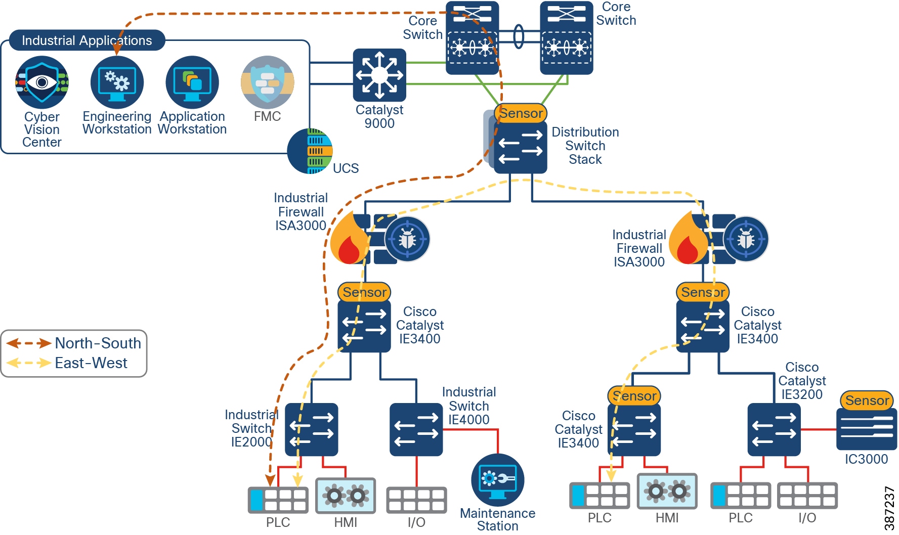
IT security architects in conjunction with a control system engineer should design an access policy that specifies the East-West and North-South communication flows that must be allowed in an IACS network. In an IACS network, having an open policy that allows every IACS asset to communicate with every IACS asset is convenient, but that approach increases the risk of cyber threat propagation. On the other hand, implementing a restrictive policy that does not allow any inter-Cell/Area Zone communication is also counterproductive because certain IACS assets need to access other IACS assets that exist in different Cell/Area Zones.
Given the positioning of the firewall, all the traffic between any two different Cell/Area Zones and all North-South traffic traverses the firewall. An access control policy in the firewall should be created to specify how to handle inbound and outbound network traffic for specific networks, protocols, applications, and content types based on the organization’s information security policies.
Before deploying a policy an organization should develop a list of the types needed and what security actions need to be taken. By default, all traffic that is not explicitly needed should be blocked. This practice helps reduce the risk of attack and decreases the volume of traffic on the network.
To optimize performance consider identifying first what traffic can be blocked or allowed unconditionally so it is put in fastpath. If you identify any traffic that meets this criterion it is possible to create a prefiltering rule so the traffic bypasses most inspections.
Because the exact requirements of a particular scenario are based on the specific requirements, specifying a policy that would work for all the deployments is not possible. Hence in this guide, an access policy example is shown that can be customized for use in different environments.
Segmentation Policy Example—Part 1 and Segmentation Policy Example—Part 2 show a segmentation policy configured on FMC that follows the structure described in Access Rules in Industrial Automation Example.
Figure 26 Segmentation Policy Example—Part 1
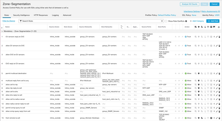
Figure 27 Segmentation Policy Example—Part 2
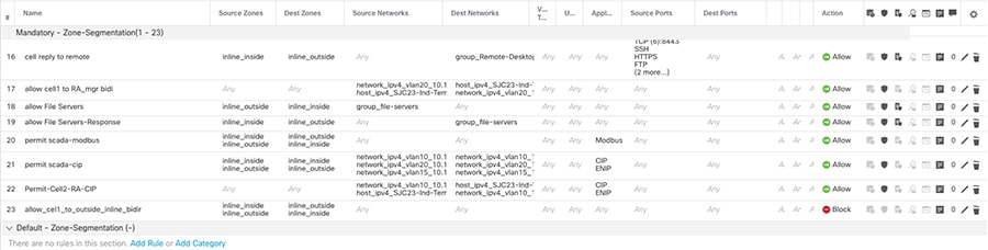
Access Rules Recommendations
■![]() For FTD interface mode inline, the firewall acts as a stateless firewall. In stateless inspection the firewall examines each packet individually, it is unaware of the packets that have passed through before it, and has no way of knowing if any given packet is part of an existing connection. Therefore, you must make sure your ACLs are designed for packets flowing in both directions.
For FTD interface mode inline, the firewall acts as a stateless firewall. In stateless inspection the firewall examines each packet individually, it is unaware of the packets that have passed through before it, and has no way of knowing if any given packet is part of an existing connection. Therefore, you must make sure your ACLs are designed for packets flowing in both directions.
■![]() Understanding the order of operations is critical for performance; reading the following document is recommended :
Understanding the order of operations is critical for performance; reading the following document is recommended :
https://www.cisco.com/c/dam/en/us/td/docs/security/firepower/Self-Help/NGFW_Policy_Order_of_Operations.pdf.
■![]() When inserting a firewall and creating policies in a new environment, start by allowing all traffic with logging enabled to understand traffic flows. When a new required flow is identified you can create a rule for it. When you have created rules to match all the traffic needed in the network change the default behavior to block.
When inserting a firewall and creating policies in a new environment, start by allowing all traffic with logging enabled to understand traffic flows. When a new required flow is identified you can create a rule for it. When you have created rules to match all the traffic needed in the network change the default behavior to block.
■![]() If one condition is enough to match the traffic you want to handle, do not use two.
If one condition is enough to match the traffic you want to handle, do not use two.
■![]() Minimize individual rule criteria. Use as few individual elements in rule conditions as possible. For example, in network conditions use IP address blocks rather than individual IP addresses.
Minimize individual rule criteria. Use as few individual elements in rule conditions as possible. For example, in network conditions use IP address blocks rather than individual IP addresses.
■![]() Combining elements into objects does not improve performance. For example, using a network object that contains 50 individual IP addresses gives you only an organizational—not a performance—benefit over including those IP addresses in the condition individually.
Combining elements into objects does not improve performance. For example, using a network object that contains 50 individual IP addresses gives you only an organizational—not a performance—benefit over including those IP addresses in the condition individually.
■![]() As much as possible, use rule conditions to narrowly define the traffic handled by resource-intensive rules. Focused rules are also important because rules with broad conditions can match many different types of traffic and can preempt later, more specific rules. Examples of resource-intensive rules include:
As much as possible, use rule conditions to narrowly define the traffic handled by resource-intensive rules. Focused rules are also important because rules with broad conditions can match many different types of traffic and can preempt later, more specific rules. Examples of resource-intensive rules include:
–![]() SSL rules that decrypt traffic—Not only the decryption, but further analysis of the decrypted traffic, requires resources. Narrow focus and where possible block or choose not to decrypt encrypted traffic.
SSL rules that decrypt traffic—Not only the decryption, but further analysis of the decrypted traffic, requires resources. Narrow focus and where possible block or choose not to decrypt encrypted traffic.
–![]() Access control rules that invoke deep inspection—Intrusion, file, and malware inspection requires resources. Make sure you only invoke deep inspection where required.
Access control rules that invoke deep inspection—Intrusion, file, and malware inspection requires resources. Make sure you only invoke deep inspection where required.
■![]() When new applications or devices are introduced in the network, the organization’s requirements may change and the policy rules may need to be updated.
When new applications or devices are introduced in the network, the organization’s requirements may change and the policy rules may need to be updated.
■![]() Firewall performance needs to be monitored to address any potential resource issues.
Firewall performance needs to be monitored to address any potential resource issues.
■![]() If you want to analyze if an ACL is being used, you can use access-list hit count. For further analysis you can enable logging for an access control rule. Connection details for ACLs with logging enabled are displayed in FMC Connection Events.
If you want to analyze if an ACL is being used, you can use access-list hit count. For further analysis you can enable logging for an access control rule. Connection details for ACLs with logging enabled are displayed in FMC Connection Events.
■![]() A CIP session can include multiple applications in different packets and a single CIP packet can contain multiple applications. The CIP preprocessor handles all CIP and ENIP traffic according to the corresponding intrusion rule. Because of that, the following configuration was validated and it is the recommended option for implementation. When creating ACL for CIP traffic only use AppIDs CIP and ENIP with an allow action. Create inspection rule to detect further. See Understanding CIP Events.
A CIP session can include multiple applications in different packets and a single CIP packet can contain multiple applications. The CIP preprocessor handles all CIP and ENIP traffic according to the corresponding intrusion rule. Because of that, the following configuration was validated and it is the recommended option for implementation. When creating ACL for CIP traffic only use AppIDs CIP and ENIP with an allow action. Create inspection rule to detect further. See Understanding CIP Events.
Segment Use Cases
The following use cases are enabled by ISA 3000 in the Industrial Security Design.
Standard Zone Segmentation (62443-3-3)
Segmentation is a core and foundational capability for access control and limiting or isolating the spread of security incidents across a network. As described in previous section, this design provides guidelines and examples to define ACLs for communicating to devices into the zone and for the devices in that zone communicating with devices outside that zone.
Use Cisco Cyber Vision Flow Discovery Capabilities to Create Firewall Rules
In order to implement ACLs and policies such that manufacturing operations are successful, and the threat surface is minimized, use Cisco Cyber Vision to discover network flows as input for creating ACL policies. Follow these steps:
1.![]() Discover flows using Cisco Cyber Vision Sensor to gather information about traffic flows in your network. Run Cisco Cyber Vision Sensor on the aggregation switch below the firewall and monitor traffic on the physical interface connected to it. When deployed in this place, the sensor will capture all flows relevant to the ISA 3000.
Discover flows using Cisco Cyber Vision Sensor to gather information about traffic flows in your network. Run Cisco Cyber Vision Sensor on the aggregation switch below the firewall and monitor traffic on the physical interface connected to it. When deployed in this place, the sensor will capture all flows relevant to the ISA 3000.
2.![]() Cisco Cyber Vision network map or activity lists can be used to see what devices are communicating through the firewall when the sensor is placed as recommended on step 1. Reporting feature can be used to generate an activity report for a desired observation period. The report includes information such as network devices, ports, protocol, and tags. This may be useful to understand flows in the network before implementing segmentation rules.
Cisco Cyber Vision network map or activity lists can be used to see what devices are communicating through the firewall when the sensor is placed as recommended on step 1. Reporting feature can be used to generate an activity report for a desired observation period. The report includes information such as network devices, ports, protocol, and tags. This may be useful to understand flows in the network before implementing segmentation rules.
3.![]() Relevant ACL rules are created on FMC.
Relevant ACL rules are created on FMC.
Note: It is recommended that when inserting a firewall and creating policies in a new environment, start by allowing all traffic with logging enabled for period until you are comfortable with the new rules. After that, change the default behavior to block.
4.![]() Deploy ACLs to the ISA 3000.
Deploy ACLs to the ISA 3000.
Figure 28 Discover Used Protocols and Block Unused Protocols
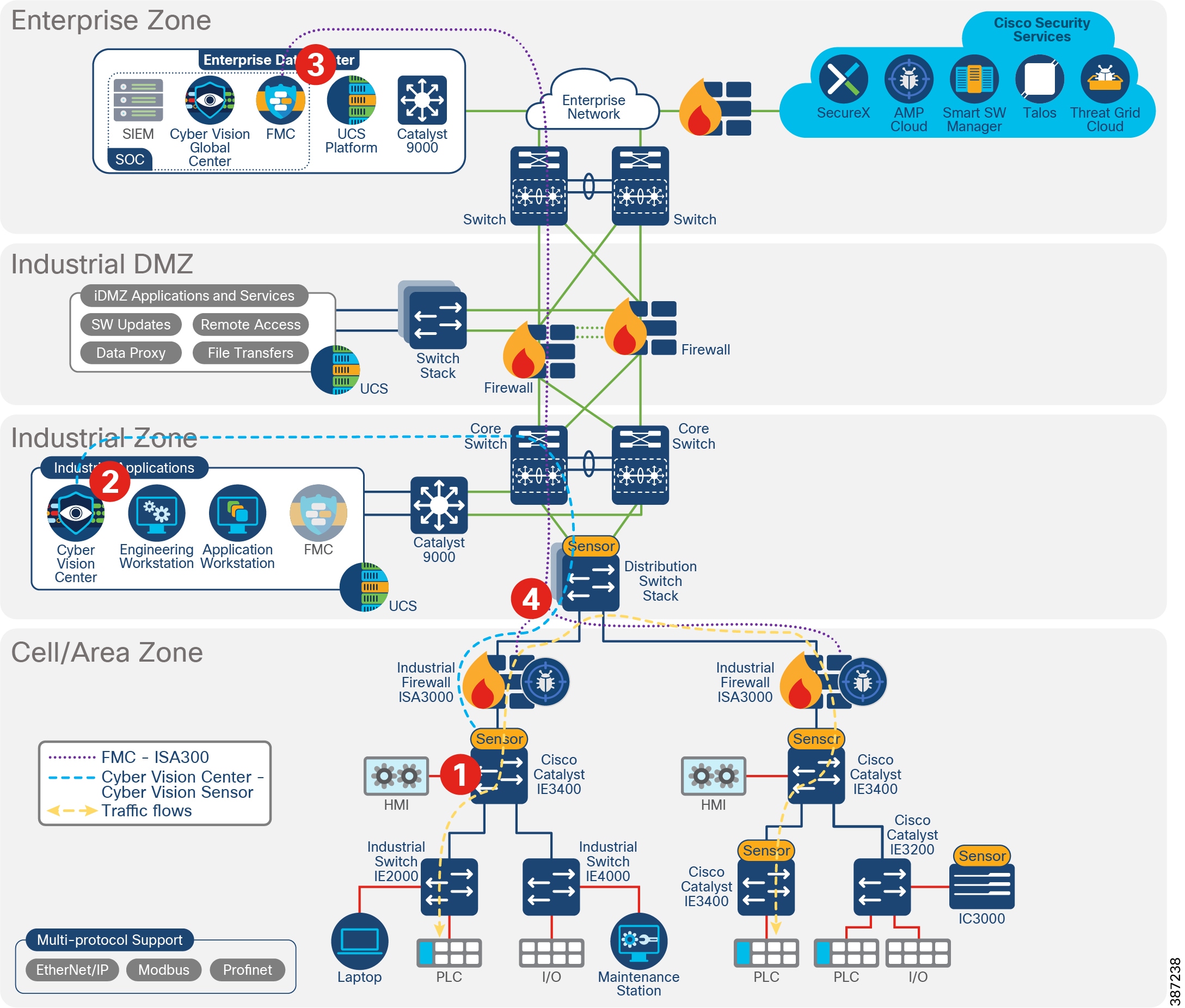
Detect and Respond
Detect and respond capabilities are the active capabilities used to monitor the network for cyber security issues and vulnerabilities and then address or mitigate the issues. This design leverages the components introduced before to detect threats. ISA 3000 is used for intrusion detection and malware detection. Cisco Cyber Vision is used to detect vulnerabilities on assets and flow anomalies. Both solution components have the capability to integrate with SecureX for incident investigation.
The detect and respond section of this document covers the following topics:
■![]() Firepower Deep Inspection Using File and Intrusion Policies—ISA 3000 performs deep packet inspection to detect network threats. This subsection covers Firepower intrusion concepts used in this design so the reader can understand the context of the recommendations. Some concepts explained in this section include network analysis policy used to provide context to intrusion events and improve FMC recommendations, intrusion and file policies, and SCADA protocol inspection. If you are familiar with Firepower deep inspection policies and elements you can skip this section.
Firepower Deep Inspection Using File and Intrusion Policies—ISA 3000 performs deep packet inspection to detect network threats. This subsection covers Firepower intrusion concepts used in this design so the reader can understand the context of the recommendations. Some concepts explained in this section include network analysis policy used to provide context to intrusion events and improve FMC recommendations, intrusion and file policies, and SCADA protocol inspection. If you are familiar with Firepower deep inspection policies and elements you can skip this section.
■![]() Cisco Cyber Vision Knowledge Database—Introduces Cisco Cyber Vision Database to detect known vulnerabilities in assets included in inventory.
Cisco Cyber Vision Knowledge Database—Introduces Cisco Cyber Vision Database to detect known vulnerabilities in assets included in inventory.
■![]() Cisco Cyber Vision Monitor Mode—Explains how to use Cisco Cyber Vision to detect flow anomalies.
Cisco Cyber Vision Monitor Mode—Explains how to use Cisco Cyber Vision to detect flow anomalies.
■![]() SecureX—This Cisco service is provided to aggregate and correlate data from different security products. Cisco Cyber Vision has the capability to start an investigation on SecureX and ISA 3000 sends intrusion events to SecureX.
SecureX—This Cisco service is provided to aggregate and correlate data from different security products. Cisco Cyber Vision has the capability to start an investigation on SecureX and ISA 3000 sends intrusion events to SecureX.
■![]() Detect and Respond Design Considerations—Provides guidance and recommendations to implement intrusion capabilities on ISA 3000 and explains FMC internet access requirements and alternatives. It provides recommendations for Cisco Cyber Vision KDB and monitoring mode.
Detect and Respond Design Considerations—Provides guidance and recommendations to implement intrusion capabilities on ISA 3000 and explains FMC internet access requirements and alternatives. It provides recommendations for Cisco Cyber Vision KDB and monitoring mode.
■![]() Detect and Respond Use Cases—Showcases detect and respond use cases validated on the CVD.
Detect and Respond Use Cases—Showcases detect and respond use cases validated on the CVD.
Firepower Deep Inspection Using File and Intrusion Policies
The term intrusion detection generally refers to the process of passively monitoring and analyzing network traffic for potential intrusions and storing attack data for security analysis. This is referred to as an Intrusion Detection System (IDS). Intrusion prevention includes the concept of intrusion detection but adds the ability to block or alter malicious traffic as it travels across your network. This is referred to as an Intrusion Prevention System (IPS). When the industrial firewall is deployed inline (as in this design) it provides IPS capabilities.
Deep inspection uses intrusion and file policies as the last line of defense before traffic is allowed to its destination. Intrusion policies govern the system’s intrusion prevention capabilities. File policies govern the system's file control and AMP for Networks capabilities.
Access control occurs before deep inspection. An access control rule and the access control default action determine which traffic is inspected by intrusion and file policies. By associating an intrusion or file policy with an access control rule, you are telling the system that before it passes traffic that matches the access control rule’s conditions, you first want to inspect the traffic with an intrusion policy, a file policy, or both.
An access control rule invokes various other policies to inspect and handle matching traffic in the following order:
1.![]() Discovery: Network Discovery Policy—First, the network discovery policy inspects traffic for discovery data. Discovery is passive analysis and does not affect the flow of traffic.
Discovery: Network Discovery Policy—First, the network discovery policy inspects traffic for discovery data. Discovery is passive analysis and does not affect the flow of traffic.
2.![]() AMP for Networks and File Control: File Policy—After traffic is inspected by discovery, the system can inspect it for prohibited files and malware. Within file inspection, simple blocking by type takes precedence over malware inspection and blocking.
AMP for Networks and File Control: File Policy—After traffic is inspected by discovery, the system can inspect it for prohibited files and malware. Within file inspection, simple blocking by type takes precedence over malware inspection and blocking.
3.![]() Intrusion Prevention: Intrusion Policy—After file inspection, the system can inspect traffic for intrusions and exploits. An intrusion policy examines decoded packets for attacks based on patterns and can block or alter malicious traffic. Intrusion policies are paired with variable sets, which allow you to use named values to accurately reflect your network environment.
Intrusion Prevention: Intrusion Policy—After file inspection, the system can inspect traffic for intrusions and exploits. An intrusion policy examines decoded packets for attacks based on patterns and can block or alter malicious traffic. Intrusion policies are paired with variable sets, which allow you to use named values to accurately reflect your network environment.
4.![]() Destination—Traffic that passes all the checks described above passes to its destination.
Destination—Traffic that passes all the checks described above passes to its destination.
Traffic that does not match any access control rules in the policy with an action other than Monitor is handled by the default action.
Note: The system does not perform any kind of inspection on trusted traffic. Although configuring an Allow rule with neither an intrusion nor file policy passes traffic like a Trust rule, Allow rules let you perform discovery on matching traffic.
Network Discovery Policy
Firepower system also provides visibility capabilities that allow you to create a network map of network components, identify some vulnerabilities, and give context to an attack. Note that this is not the chosen visibility tool in this design because it may not provide full visibility into the Cell Area/Zone (it only detects traffic flowing through the firewall). It is also different from Cisco Cyber Vision on the industrial devices and protocol support. Nevertheless, it is introduced in this section because of its role in intrusion prevention. On one hand, Firepower network discovery policy is used to get inspection rules recommendations to be enabled and disabled based on the hosts on your network; on the other hand, it can provide context to an intrusion event.
The network discovery policy controls how the system collects data on your organization’s network assets and which network segments and ports are monitored. Discovery rules within the policy specify which networks and ports the Firepower System monitors to generate discovery data based on network data in traffic and the zones to which the policy is deployed. You can create rules to exclude networks and zones from discovery.
Remember that the access control policy for each managed device defines the traffic that you permit for that device and, therefore, the traffic you can monitor with network discovery. If you block certain traffic using access control, the system cannot examine that traffic for host, user, or application activity. When the access control rule action is Trust, traffic is not examined either.
Benefits of customizing network discovery policies:
■![]() FMC can provide rule recommendations that match the hosts on your network.
FMC can provide rule recommendations that match the hosts on your network.
■![]() Network discovery is important for impact flags to reflect the severity of the attack. Information from known hosts is used to determine if the intrusion event by assigning a different score depending if the event occurs on the profiled networks, from known or unknown hosts, on used or unused ports or on a host showing an indication of compromise.
Network discovery is important for impact flags to reflect the severity of the attack. Information from known hosts is used to determine if the intrusion event by assigning a different score depending if the event occurs on the profiled networks, from known or unknown hosts, on used or unused ports or on a host showing an indication of compromise.
Intrusion Prevention
Intrusion policies are deployed on FTD devices to perform IPS. In an intrusion prevention deployment, when the system examines packets:
■![]() A network analysis policy governs how traffic is decoded and preprocessed so it can be further evaluated, especially for anomalous traffic that might signal an intrusion attempt.
A network analysis policy governs how traffic is decoded and preprocessed so it can be further evaluated, especially for anomalous traffic that might signal an intrusion attempt.
■![]() An intrusion policy uses intrusion and preprocessor rules to examine the decoded packets for attacks based on patterns. Intrusion policies are paired with variable sets, which allow you to use named values to accurately reflect your network environment.
An intrusion policy uses intrusion and preprocessor rules to examine the decoded packets for attacks based on patterns. Intrusion policies are paired with variable sets, which allow you to use named values to accurately reflect your network environment.
Network analysis and intrusion policies work together as part of the Firepower System’s intrusion detection and prevention feature. As the system analyzes traffic, the network analysis (decoding and preprocessing) phase occurs before and separately from the intrusion prevention (additional preprocessing and intrusion rules) phase.
The Firepower System is delivered with several similarly named network analysis and intrusion policies described in System-Provided Network Analysis and Intrusion Policies. It is recommended that you create a customized policy. When creating the policy, a system-provided one is used as a base layer and is customized to inspect traffic in the way that matters most to you so that you can improve both the performance of your managed devices and your ability to respond effectively to the events they generate. For this validation, connectivity over security and connectivity policy was used as a base. For industrial traffic, SCADA rules were added as described in Intrusion Policy.
System-Provided Network Analysis and Intrusion Policies lists the system-provided network analysis and intrusion policies.
In an inline deployment the system can block traffic without further inspection. Similarly, at each step of the process, a packet could cause the system to generate an event. Intrusion events are indications that a packet or its contents may represent a security risk.
Network Analysis Policy
Without decoding and preprocessing, the system could not appropriately evaluate traffic for intrusions because protocol differences would make pattern matching impossible. Network analysis policies govern these traffic-handling tasks before traffic matches access control rules and can be inspected by file or intrusion policies. This policy is relevant to the industrial automation design because it allows you to enable SCADA preprocessors and settings.
In a newly created access control policy, one default network analysis policy governs preprocessing for all intrusion policies invoked by the same parent access control policy. Initially, the system uses the Balanced Security and Connectivity network analysis policy as the default, but you can change it to another system-provided or custom network analysis policy.
The SCADA preprocessors are enabled and configured in the network analysis policy. Because they are disabled by default, you should at least customize the policy to enable the preprocessors for industrial automation environments.
Figure 29 Enable SCADA Preprocessors
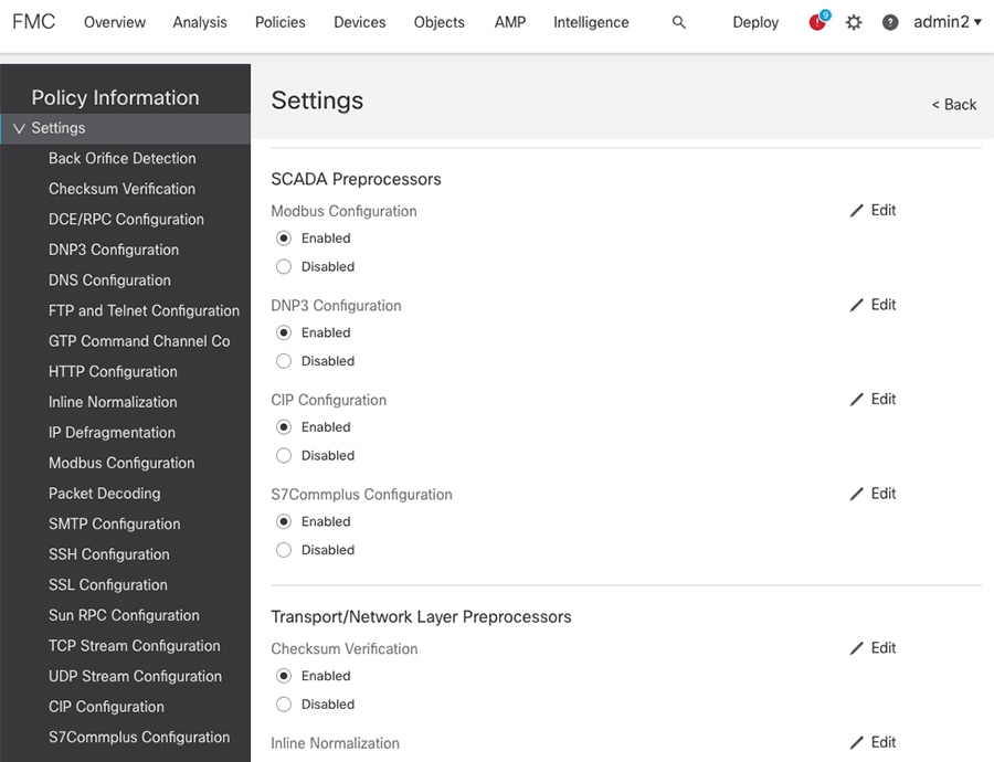
For more information on configuring preprocessors settings, refer to the Firepower Management Center Configuration Guide at:
https://www.cisco.com/c/en/us/td/docs/security/firepower/670/configuration/guide/fpmc-config-guide-v67.html.
Intrusion Policy
You can use intrusion prevention as the system’s last line of defense before traffic is allowed to proceed to its destination. Intrusion policies govern how the system inspects traffic for security violations and, in inline deployments, can block or alter malicious traffic. The main function of intrusion policies is to manage which intrusion and preprocessor rules are enabled and how they are configured.
An intrusion rule is a specified set of keywords and arguments that detects attempts to exploit vulnerabilities on your network; the system uses an intrusion rule to analyze network traffic to check if it matches the criteria in the rule. The system compares packets against the conditions specified in each rule and, if the packet data matches all the conditions specified in a rule, the rule triggers.
Intrusion Rule Example shows an example of a system-provided intrusion rule “PROTOCOL-SCADA Cisco IE2000 CIP get attributes all packet processing memory leak attempt”.
Figure 30 Intrusion Rule Example
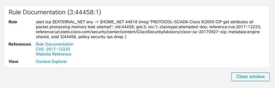
The system includes rules created by Talos. Some of the provided rules are preprocessor rules, which are rules associated with preprocessors and packet decoder detection options in the network analysis policy. Most preprocessor rules are disabled by default; you must enable them in an intrusion policy to generate events and, in an inline deployment, drop offending packets. Enable Preprocessor Rules shows how to search for SCADA Preprocessor CIP rules to enable them. On a given intrusion policy, navigate to the rules tab and search for the preprocessor option on the list. You can select the desired preprocessor and change the state of the rules to Generate Events, Drop and Generate Events, or Disable.
Figure 31 Enable Preprocessor Rules
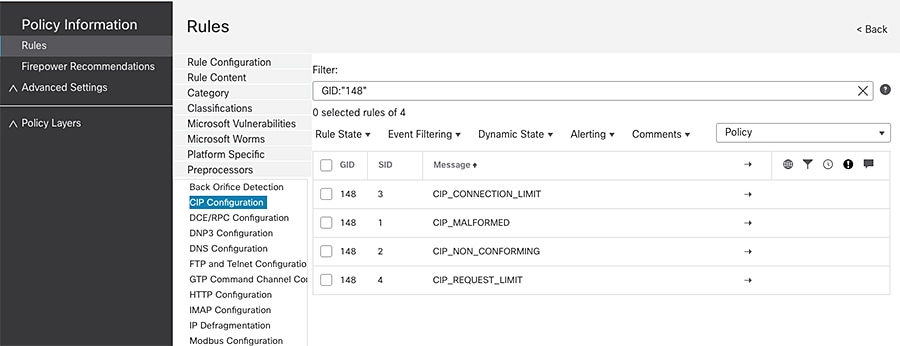
The system also includes some rules for SCADA protocols. To select those on an intrusion policy, go to rules -> Category -> Protocol-scada and select the ones that apply to your network.
As explained, in a custom intrusion policy, you can tune detection by enabling and disabling rules, as well as by writing and adding your own standard text rules. Some examples of customized rules are provided in Creating SCADA Custom Inspection Rules.
Firepower also provides recommendations to associate to your policy based on the hosts on your network, the operating systems, servers, and client application protocols detected on your network with rules specifically written to protect those assets. For more information on Firepower recommendations, refer to the FMC configuration guide at:
https://www.cisco.com/c/en/us/td/docs/security/firepower/670/configuration/guide/fpmc-config-guide-v67/tailoring_intrusion_protection_to_your_network_assets.html.
SCADA Protocol Inspection
There are built-in inspection rules for SCADA protocols. They are disabled by default. To enable them you can search preprocessors rule as explained in previous section or you can use the Generator ID number (GID). Each preprocessor has its own GID that indicates which preprocessor was triggered by the packet. Some of the preprocessors also have related SIDs, which are ID numbers that classify potential attacks. This helps you analyze events more effectively by categorizing the type of event much the way a rule's Snort ID (SID) can offer context for packets triggering rules. The following list contains the GIDs for SCADA preprocessors:
Creating SCADA Custom Inspection Rules
The following section introduces customized inspection rules that apply to SCADA protocols. To create a custom rule, you must be familiar with standard text rules components. An intrusion rule is a set of keywords and arguments that the system uses to detect attempts to exploit vulnerabilities on your network. As the system analyzes network traffic, it compares packets against the conditions specified in each rule. If the packet data matches all the conditions specified in a rule, the rule triggers. You can view and evaluate intrusion events from the FMC web interface. You can write custom standard text rules to tune the types of events you are likely to see.
All standard text rules contain two logical sections: the rule header and the rule options. The rule header contains:
■![]() The rule’s action or type—If a rule is an alert rule, it generates an intrusion event. If it is a pass rule, it ignores the traffic. For a drop rule in an inline deployment, the system drops the packet and generates an event.
The rule’s action or type—If a rule is an alert rule, it generates an intrusion event. If it is a pass rule, it ignores the traffic. For a drop rule in an inline deployment, the system drops the packet and generates an event.
■![]() The protocol—ICMP, IP, TCP, UDP
The protocol—ICMP, IP, TCP, UDP
■![]() The source and destination IP addresses and netmasks
The source and destination IP addresses and netmasks
■![]() Direction indicators showing the flow of traffic from source to destination:
Direction indicators showing the flow of traffic from source to destination:
–![]() Directional—Only traffic from the specified source IP address to the specified destination IP address
Directional—Only traffic from the specified source IP address to the specified destination IP address
–![]() Bidirectional—All traffic traveling between the specified source and destination IP addresses
Bidirectional—All traffic traveling between the specified source and destination IP addresses
■![]() The source and destination ports
The source and destination ports
The rule options section contains:
■![]() Event messages—Text that will be displayed in an intrusion event
Event messages—Text that will be displayed in an intrusion event
■![]() Keywords and their parameters and arguments
Keywords and their parameters and arguments
■![]() Patterns that a packet’s payload must match to trigger the rule
Patterns that a packet’s payload must match to trigger the rule
A rule can contain one or more keywords to match and a packet should match all conditions in the rule.
Note: Each preprocessor provides a set of keywords to access protocol fields. For SCADA keywords see:
https://www.cisco.com/c/en/us/td/docs/security/firepower/670/configuration/guide/fpmc-config-guide-v67/the_intrusion_rules_editor.html#ID-2235-0000226f.
Custom S7Commplus Rule
The S7Commplus preprocessor is a Snort module that decodes the S7Commplus protocol. It also provides rule options to access certain protocol fields. This allows a user to write rules for S7Commplus packets. You can use the S7Commplus keywords alone or in combination to create custom intrusion rules that identify attacks against traffic detected by the S7Commplus preprocessor. For configurable keywords, specify a single known value or a single integer within the allowed range.
S7Commplus Rule shows an example of customized rule to detect a create object request. It uses the keywords s7commplus_opcode that specifies the direction of the transaction and s7commplus_func that specifies the function that needs to be performed by the PLC.
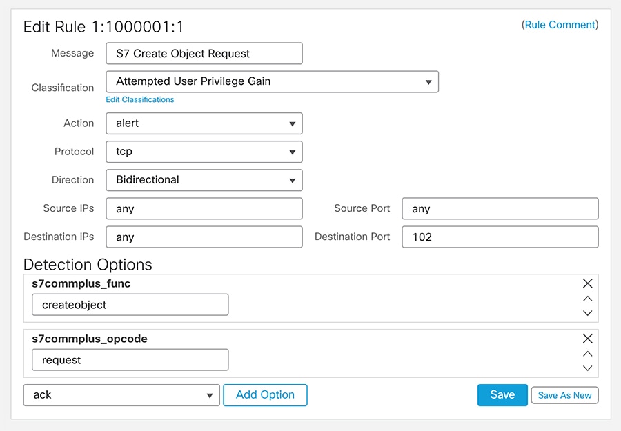
Note: Using multiple s7commplus_func or s7commplus_opcode keywords in the same rule negates the rule and it will never match traffic. To search for multiple values with these keywords, create multiple rules.
Custom CIP Rule
It is possible to create inspection rules that could match on individual fields within a packet (for example, CIP class and service fields). You can use CIP keywords alone or in combination to create custom intrusion rules that identify attacks against CIP and ENIP traffic detected by the CIP preprocessor. For configurable keywords, specify a single integer within the allowed range.
CIP Rule shows an inspection rule to detect modifications of an attribute value using service instance Set_Attribute_Single (0x10).
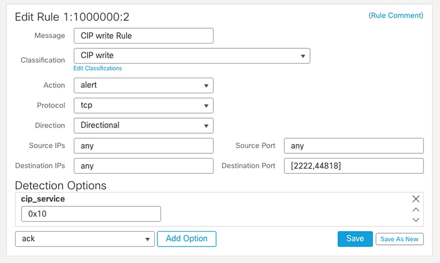
Note: Cisco Cyber Vision has a packet capture functionality on its sensors. Capturing traffic and analyzing the packets in the network can provide information on detection options to use.
Note: CIP detection needs to be configured using IPS rules instead of AppID as it helps in logging each transaction irrespective of the end or beginning of the connection.
Custom Modbus Rules
Similar to the S7Commplus and CIP rules shown before, you can use Modbus keywords alone or in combination with other keywords. Modbus Rule shows a Modbus Intrusion rule to detect Modbus Write Single Coil function.
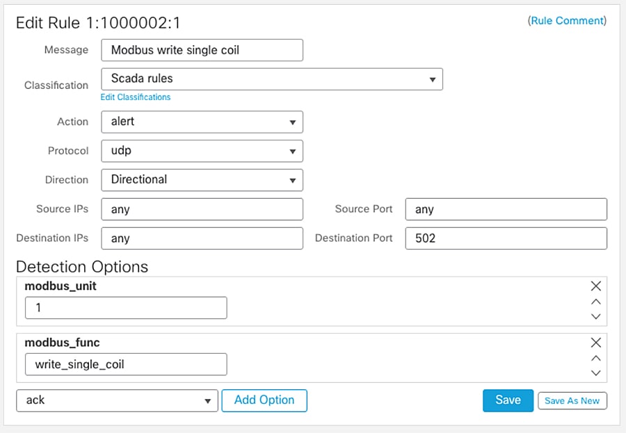
Variable Sets
Variables represent values commonly used in intrusion rules to identify source and destination IP addresses and ports. FMC provides a default variable set, but it is possible to create your own custom sets. In this design the variable set was customized to identify networks protected by the firewall.
Most of the shared object rules and standard text rules that the Firepower System provides use predefined default variables to define networks and port numbers. For example, the majority of the rules use the variable $HOME_NET to specify the protected network and the variable $EXTERNAL_NET to specify the unprotected (or outside) network. Customizing the variable set will provide directionality to the rules.
Rules are more effective when variables more accurately reflect your network environment. During Foundation Industrial Security validation $HOME_NET was modified to match IP addresses in the Cell/Area Zone being protected and $EXTERNAL_NET for any network but $HOME_NET. Appendix D—System-Provided Variables contains a list of variables in default variable set and guidance in which ones should be modified.
To use your variables, you link variable sets to intrusion policies associated with access control rules or with the default action of an access control policy. By default, the Firepower System links the default variable set to all intrusion policies used in an access control policy. When you deploy an access control policy that uses an intrusion policy, intrusion rules that you have enabled in the intrusion policy use the variable values in the linked variable set. Using a Variable Set shows where to link a variable set to an intrusion policy when editing an access control rule.
Figure 35 Using a Variable Set
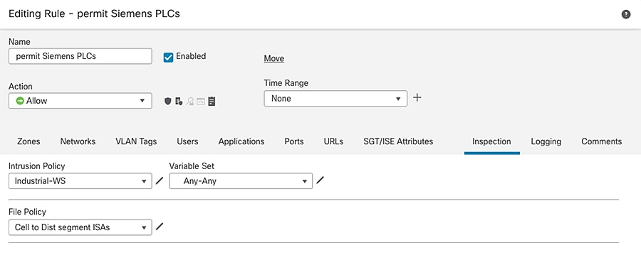
Intrusion Event Generation
When the system identifies a possible intrusion, it generates an intrusion or preprocessor event. Managed devices transmit their events to the FMC, where they can be analyzed to gain a greater understanding of the attacks against your network assets. In an inline deployment, managed devices can also drop or replace packets that you know to be harmful. As the database accumulates intrusion events, you can begin your analysis of potential attacks. The system provides you with the tools you need to review intrusion events and evaluate whether they are important in the context of your network environment and your security policies.
Understanding CIP Events
By design, application detectors detect and event viewers display the same application one time per session. A CIP session can include multiple applications in different packets and a single CIP packet can contain multiple applications. The CIP preprocessor handles all CIP and ENIP traffic according to the corresponding intrusion rule.
CIP Event Field Values shows the CIP values displayed in event views.
Interruptions to Traffic Flow and Inspection During Deploy
When you deploy changes on the devices from FMC, resource demands may result in a small number of packets dropping without inspection. Additionally, deploying some configurations restarts the Snort process, which interrupts traffic inspection. If the Snort process needs to be restarted a dialog warns of the potential interruption prior to deployment. You can either proceed with, cancel, or delay deployment. Whether traffic drops during this interruption or passes without further inspection depends on how the target device handles traffic. For FTD interfaces configured as inline traffic action during Snort restart is determined by the inline interface setting Snort Fail Open: Down option. When disabled, traffic is dropped during Snort restart. When enabled, traffic passes without inspection. Snort Fail Open Configuration shows inline set configuration that allows traffic without inspection while Snort process is restarting.
Figure 36 Snort Fail Open Configuration
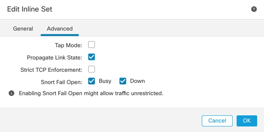
Note: Traffic may be inspected during policy application if traffic during policy apply setting is enabled (default). Inspection will continue unless a configuration that you deploy requires the Snort process to restart.
File Analysis and Malware Detection
File Policies can be enabled to detect and block malware and to detect and control traffic by file type. You associate file policies with access control rules that handle network traffic as part of your overall access control configuration. If your organization wants to block not only the transmission of malware files, but all files of a specific type (regardless of whether the files contain malware), file control allows you to monitor network traffic for transmissions of specific file types, then either block or allow the file.
AMP for Firepower can detect, capture, track, analyze, log, and optionally block the transmission of malware in network traffic. In the FMC web interface, this feature is called AMP for Networks. Depending on the options you enable in a file rule, the system inspects files for malware using local and/or cloud-based tools.
A file policy is a set of configurations that the system uses to perform malware protection and file control as part of your overall access control configuration. This association ensures that before the system passes a file in traffic that matches an access control rule’s conditions, it first inspects the file. By associating different file policies with different access control rules, you have granular control over how you identify and block files transmitted on your network. Within file inspection, simple blocking by type takes precedence over malware inspection and blocking.
When the system detects malware on your network, it generates file and malware events. To further target your analysis, you can use a malware file's network file trajectory (a map of how the file traversed your network, passing among hosts, as well as various file properties) to track the spread of an individual threat across hosts over time, allowing you to concentrate outbreak control and prevention efforts where most useful.
License requirements for file policies depend on the required capabilities.
■![]() Block or allow all files of a particular type requires Threat license.
Block or allow all files of a particular type requires Threat license.
■![]() Selectively allow or block files based on a judgment that it contains or is likely to contain malware requires Malware and Threat licenses.
Selectively allow or block files based on a judgment that it contains or is likely to contain malware requires Malware and Threat licenses.
■![]() Store files requires Malware and Threat licenses.
Store files requires Malware and Threat licenses.
For more information on file policies, configuration, and best practices see:
https://www.cisco.com/c/en/us/td/docs/security/firepower/670/configuration/guide/fpmc-config-guide-v67/file_policies_and_advanced_malware_protection.html.
Cloud Connections for Malware Protection
Connections to public or private clouds are required in order to protect your network from malware. The following section describes those clouds and deployment options for deployments with restricted cloud connectivity.
Note: The design was validated with direct cloud connectivity but on-prem options should be considered.
AMP Clouds
AMP cloud is a Cisco-hosted server that uses big data analytics and continuous analysis to provide intelligence that the system uses to detect and block malware on your network. The AMP cloud provides dispositions for possible malware detected in network traffic by managed devices, as well as data updates for local malware analysis and file pre-classification.
Cisco offers the following options for obtaining data from the Cisco cloud about known malware threats:
■![]() AMP public cloud—Your FMC communicates directly with the public Cisco cloud.
AMP public cloud—Your FMC communicates directly with the public Cisco cloud.
■![]() An AMP private cloud is deployed on your network and acts as a compressed, on-premises AMP cloud. The Cisco AMP Private Cloud Appliance supports two deployment modes: “cloud proxy mode” and “air-gap mode.”
An AMP private cloud is deployed on your network and acts as a compressed, on-premises AMP cloud. The Cisco AMP Private Cloud Appliance supports two deployment modes: “cloud proxy mode” and “air-gap mode.”
For details see:
https://www.cisco.com/c/en/us/td/docs/security/firepower/60/configuration/guide/fpmc-config-guide-v60/Reference_a_wrapper_Chapter_topic_here.html#ID-2193-0000051c.
Dynamic Analysis Cloud
Cisco Threat Grid runs eligible files in a sandbox environment and returns a threat score and dynamic analysis report to the Firepower System.
■![]() Cisco Threat Grid cloud—FTD devices send files directly to the cloud.
Cisco Threat Grid cloud—FTD devices send files directly to the cloud.
■![]() On-premises Cisco Threat Grid appliance—If your organization’s security policy does not allow the Firepower System to send files outside of your network, you can deploy an on-premises appliance. This appliance does not contact the public Cisco Threat Grid cloud. For more information see:
On-premises Cisco Threat Grid appliance—If your organization’s security policy does not allow the Firepower System to send files outside of your network, you can deploy an on-premises appliance. This appliance does not contact the public Cisco Threat Grid cloud. For more information see:
https://www.cisco.com/c/en/us/td/docs/security/firepower/60/configuration/guide/fpmc-config-guide-v60/Reference_a_wrapper_Chapter_topic_here.html#concept_71E2BDBBF3FB40F6B660B1165E2B65D8.
Cisco Cyber Vision Knowledge Database
Cisco Cyber Vision uses an internal knowledge database (KDB) which contains the list of recognized vulnerabilities, icons, threats, and so on.
These rules are sourced from several CERTs (Computer Emergency Response Team), manufacturers, and partner manufacturers (Schneider, Siemens, and so on). Technically, vulnerabilities are generated from the correlation of the KDB rules and normalized component properties. A vulnerability is detected when a component's properties (version, model, and so on) matches a KDB rule.
It is important to update the KDB in Cisco Cyber Vision with each new revision to be protected against vulnerabilities.
Cisco Cyber Vision Monitor Mode
Cisco Cyber Vision can be used to detect changes inside industrial networks. Because a network architecture (PLC, switch, SCADA) is constant and its behaviors tend to be stable over time, an established and configured network is predictable. However, some behaviors are unpredictable and can even compromise a network’s operation and security. Cyber Vision Monitor mode aims to show the evolution of a network’s behaviors, predicted or not, based on presets. Changes, either normal or abnormal, are noted as differences when a behavior happens.
Using the Monitor mode is particularly convenient for large networks as a preset shows a network fragment and changes are highlighted and managed separately, in the Monitor mode’s views.
A Preset is a set of criteria which aims to show a detailed fragment of a network. To start monitoring a network, you need to configure a preset and define what would be its normal, stable state. This will represent the preset's baseline.
A state may rely on a period, as a network fragment may be subject to several states. Hence, it is possible to create several planned, controlled and time-framed baselines per preset, and to monitor the whole network. For example, a normal state of the network can be a typical weekday operating mode, in which numerous processes are performed iteratively. During weekends, these processes may be slowed down or even stopped. Any network phase can be saved as a baseline by selecting a time span. Other examples of baselines can be a regular maintenance period, a degraded mode, a weekend and night mode, and so forth.
A baseline is created for a situation considered as part of a normal operating process in which all network behaviors (components, activities, properties, tags, variable accesses) will be taken into account for review. Any difference detected is highlighted. When reviewing these, they can be acknowledged and included in a new baseline or reported. It depends on whether the operator considers it normal or not. By acknowledging changes, each baseline is refined over time to match the evolving environment.
SecureX
SecureX is a cloud-native, built-in platform experience within Cisco Secure portfolio and connected to your infrastructure. It combines multiple otherwise disparate sensor and detection technologies into one unified location for visibility and provides automation and orchestration capabilities to maximize operational efficiency, all to secure your network, users and endpoints, cloud edge, and applications.
SecureX connects the breadth of Cisco's integrated security portfolio and your entire security infrastructure for a consistent experience that unifies visibility, enables automation, and strengthens your security across the network, endpoint, cloud, and applications. The result is simplified security built into the solutions that you already have.
SecureX threat response integrates threat intelligence from Cisco Talos and third-party sources to automatically research Indicators of Compromise (IOCs), also known as observables, and confirm threats quickly.
Cisco Firepower devices send data to SecureX threat response via a secure intermediary cloud service called Cisco Security Service Exchange (SSE). SecureX threat response queries the SSE for sightings related to the IP address being investigated and provides the SOC analyst with the additional context. Intrusion events are promoted to investigation-worthy incidents in the Incident Manager based on Talos poor IP reputation or user-defined filters for notable IP addresses or by the user manually. This allows the administrator to investigate incidents and speeds up the time needed to perform triage and analytics on intrusion events.
SecureX and SecureX threat response are available for all Cisco Secure Firewall customers. FTD devices can send events directly to the cloud or they can use syslog to send supported events to the Cisco cloud from Firepower devices.
Firepower and SecureX Direct Integration
Firepower devices send events to SSE, from where they can be automatically or manually promoted to incidents that appear in Cisco SecureX threat response. FMC and managed devices must be able to connect outbound on port 443 to the Cisco regional cloud.
Firepower and SecureX Integration Via Syslog
Syslog is used to send supported events to the Cisco cloud from Firepower devices. You must set up an on-premises Cisco Security Services Proxy (CSSP) server and configure your devices to send syslog messages to this proxy. CSSP requires direct Internet access so that it will integrate with the Cisco Security Service Exchange and Cisco SecureX Cloud. Every 10 minutes, the proxy forwards collected events to SSE, from where they can be automatically or manually promoted to incidents that appear in Cisco SecureX threat response.
CSSP is free and it can be downloaded from SSE portal. For more information see:
https://admin.sse.itd.cisco.com/assets/static/online-help/index.html#!t_download_the_cssp_installer_and_documentation.html.
Note: Direct Integration option was used for validation of this design.
Firepower and SecureX Integration Requirements
The following information is applicable to Firepower release 6.7. For earlies versions check FMC documentation.
■![]() In order to use SecureX and associated tools including SSE, you must have one of the following accounts on the regional cloud you will use:
In order to use SecureX and associated tools including SSE, you must have one of the following accounts on the regional cloud you will use:
■![]() The Firepower system must be licensed to generate the events that you want to view in SecureX.
The Firepower system must be licensed to generate the events that you want to view in SecureX.
–![]() Integration is not supported under a Firepower evaluation license.
Integration is not supported under a Firepower evaluation license.
–![]() For direct cloud connections, network cannot be using a Cisco Smart Software Manager On-Prem server.
For direct cloud connections, network cannot be using a Cisco Smart Software Manager On-Prem server.
■![]() Network cannot be deployed in an air-gapped environment.
Network cannot be deployed in an air-gapped environment.
■![]() You must have administrator privileges for the Cisco Smart Account from which your products are licensed.
You must have administrator privileges for the Cisco Smart Account from which your products are licensed.
■![]() Your licensing Smart Account and the account you use to access the cloud must both be associated with the same Cisco CCO account.
Your licensing Smart Account and the account you use to access the cloud must both be associated with the same Cisco CCO account.
■![]() Firepower devices use communication port TCP 443 to send events.
Firepower devices use communication port TCP 443 to send events.
■![]() For regional cloud domain names refer to:
For regional cloud domain names refer to:
https://www.cisco.com/c/en/us/td/docs/security/firepower/integrations/CTR/Firepower_and_Cisco_Threat_Response_Integration_Guide/send_events_to_the_cloud_directly.html.
For more information see:
https://www.cisco.com/c/en/us/td/docs/security/firepower/integrations/SecureX/firepower-and-securex-integration-guide.html.
Cisco Cyber Vision and SecureX Threat Response Integration
Cisco Cyber Vision allows to configure the platform URL for Cisco Threat Response. Once configured it enables a button to launch an investigation on IP and MAC addresses on SecureX Threat Response.
Detect and Respond Design Considerations
The following leverages the design considerations covered in the Discover and Segment sections above. It focuses on providing some guidance on system configurations for optimal detection on industrial networks. The section also includes some overview of Firepower internet access requirements. Although the design was validated with direct cloud connectivity, there is an overview for on-prem alternatives.
Recommendations when Tunning Firepower Inspection for Industrial Networks
■![]() SCADA preprocessors are disabled by default. You should customize your network analysis policy to enable SCADA if you want to inspect SCADA protocols. You should not enable SCADA preprocessors if your network does not have SCADA traffic. Refer to Network Analysis Policy for details.
SCADA preprocessors are disabled by default. You should customize your network analysis policy to enable SCADA if you want to inspect SCADA protocols. You should not enable SCADA preprocessors if your network does not have SCADA traffic. Refer to Network Analysis Policy for details.
■![]() You can tailor your intrusion prevention deployment by creating and using custom policies. You may find that the intrusion rules do not address the security needs of your network. By tuning your network analysis and intrusion policies you can configure, at a very granular level, how the system processes and inspects the traffic on your network for intrusions. You can customize intrusion policies to enable SCADA protocol rules. The recommendation is to review those rules and enabled the ones that apply to your system.
You can tailor your intrusion prevention deployment by creating and using custom policies. You may find that the intrusion rules do not address the security needs of your network. By tuning your network analysis and intrusion policies you can configure, at a very granular level, how the system processes and inspects the traffic on your network for intrusions. You can customize intrusion policies to enable SCADA protocol rules. The recommendation is to review those rules and enabled the ones that apply to your system.
■![]() Even if you use system-provided network analysis and intrusion policies, you should configure the system's intrusion variables to accurately reflect your network environment. At a minimum, modify $HOME_NET, to match your protected networks and $EXTERNAL_NET for everything else.
Even if you use system-provided network analysis and intrusion policies, you should configure the system's intrusion variables to accurately reflect your network environment. At a minimum, modify $HOME_NET, to match your protected networks and $EXTERNAL_NET for everything else.
■![]() To customize your intrusion prevention deployment, you can create multiple intrusion policies, each tailored to inspect traffic differently. Then configure an access control policy with rules that specify which policy inspects which traffic. For example, you can create an intrusion policy with SCADA protocol rules enabled to be applied in the ACL for CIP traffic; for remote servers traffic you can use one of the system provided rules without modification.
To customize your intrusion prevention deployment, you can create multiple intrusion policies, each tailored to inspect traffic differently. Then configure an access control policy with rules that specify which policy inspects which traffic. For example, you can create an intrusion policy with SCADA protocol rules enabled to be applied in the ACL for CIP traffic; for remote servers traffic you can use one of the system provided rules without modification.
■![]() Within each intrusion policy, you should verify that all rules applicable to your environment are enabled; improve performance by disabling rules that are not applicable to your environment. In an inline deployment, you can specify which rules should drop or modify malicious packets.
Within each intrusion policy, you should verify that all rules applicable to your environment are enabled; improve performance by disabling rules that are not applicable to your environment. In an inline deployment, you can specify which rules should drop or modify malicious packets.
■![]() Firepower recommendations allow you to associate the operating systems, servers, and client application protocols detected on your network with rules specifically written to protect those assets. For this to work network analysis policy needs to be configured. Refer to Network Discovery Policy.
Firepower recommendations allow you to associate the operating systems, servers, and client application protocols detected on your network with rules specifically written to protect those assets. For this to work network analysis policy needs to be configured. Refer to Network Discovery Policy.
■![]() You can modify existing rules and write new standard text rules as needed to catch new exploits or to enforce your security policies. For example, you could detect and optionally block industrial protocol actions. Some examples were provided in Creating SCADA Custom Inspection Rules.
You can modify existing rules and write new standard text rules as needed to catch new exploits or to enforce your security policies. For example, you could detect and optionally block industrial protocol actions. Some examples were provided in Creating SCADA Custom Inspection Rules.
■![]() As new vulnerabilities become known, Talos releases intrusion rule updates. These rule updates can modify any system-provided network analysis or intrusion policy and can provide new and updated intrusion rules and preprocessor rules, modified states for existing rules, and modified default policy settings. If a rule update affects your deployment, the web interface marks affected intrusion and network analysis policies as out of date, as well as their parent access control policies. You must re-deploy an updated policy for its changes to take effect.
As new vulnerabilities become known, Talos releases intrusion rule updates. These rule updates can modify any system-provided network analysis or intrusion policy and can provide new and updated intrusion rules and preprocessor rules, modified states for existing rules, and modified default policy settings. If a rule update affects your deployment, the web interface marks affected intrusion and network analysis policies as out of date, as well as their parent access control policies. You must re-deploy an updated policy for its changes to take effect.
■![]() For your convenience, you can configure rule updates to automatically re-deploy affected intrusion policies, either alone or in combination with affected access control policies. This allows you to easily and automatically keep your deployment up to date to protect against recently discovered exploits and intrusions.
For your convenience, you can configure rule updates to automatically re-deploy affected intrusion policies, either alone or in combination with affected access control policies. This allows you to easily and automatically keep your deployment up to date to protect against recently discovered exploits and intrusions.
■![]() CIP action detection needs to be configured using IPS rules instead of AppID as it helps in logging each transaction irrespective of the beginning or end of the connection. It is recommended to create access control rules that match ENIP/CIP and create inspection rules for CIP actions.
CIP action detection needs to be configured using IPS rules instead of AppID as it helps in logging each transaction irrespective of the beginning or end of the connection. It is recommended to create access control rules that match ENIP/CIP and create inspection rules for CIP actions.
■![]() To detect specific SCADA events not existing in built-in rules, create SCADA custom intrusion rules as described in Creating SCADA Custom Inspection Rules.
To detect specific SCADA events not existing in built-in rules, create SCADA custom intrusion rules as described in Creating SCADA Custom Inspection Rules.
■![]() The CIP preprocessor does not support an access control policy default action of Access Control: Trust or Block All Traffic, which may produce undesirable behavior, including not dropping traffic triggered by CIP applications specified in intrusion rules and access control rules or dropping traffic that does not need to be dropped.
The CIP preprocessor does not support an access control policy default action of Access Control: Trust or Block All Traffic, which may produce undesirable behavior, including not dropping traffic triggered by CIP applications specified in intrusion rules and access control rules or dropping traffic that does not need to be dropped.
■![]() To block CIP or ENIP application traffic using access control rules, ensure that the inline normalization preprocessor and its Inline Mode option are enabled (the default setting) in the corresponding network analysis policy.
To block CIP or ENIP application traffic using access control rules, ensure that the inline normalization preprocessor and its Inline Mode option are enabled (the default setting) in the corresponding network analysis policy.
Using Firepower Rules Recommendations Considerations
As described earlier, FMC could provide rule recommendations to optimize the intrusion detection in your network focusing on relevant rules according to devices in the network.
Follow these guidelines when using recommendations.
■![]() Configure the network discovery policy; when network discovery policy is left to any/any, Firepower will provide recommendations for devices that are not part of the network and oversubscribe the system.
Configure the network discovery policy; when network discovery policy is left to any/any, Firepower will provide recommendations for devices that are not part of the network and oversubscribe the system.
■![]() Enabling Accept Recommendations to Disable Rules could lead to disabling rules for hosts that are not accurately represented in the host profile. We recommend leaving it unchecked.
Enabling Accept Recommendations to Disable Rules could lead to disabling rules for hosts that are not accurately represented in the host profile. We recommend leaving it unchecked.
Recommended Practices for Pushing Configuration from FMC to FTD
Follow these recommendations when applying configuration on ISA 3000 to make sure you minimize the impact on traffic inspection:
■![]() We strongly recommend you deploy in a maintenance window or at a time when interruptions will have the least impact.
We strongly recommend you deploy in a maintenance window or at a time when interruptions will have the least impact.
■![]() Set your ACL advanced option to enable inspection during deploy.
Set your ACL advanced option to enable inspection during deploy.
■![]() Review your configured action for inspection when Snort process is down. To avoid traffic interruption on the network, leave the setting unchecked.
Review your configured action for inspection when Snort process is down. To avoid traffic interruption on the network, leave the setting unchecked.
Cisco Cyber Vision Knowledge Database and Respond Best Practices
■![]() When creating a baseline make sure you provide enough runtime to capture all flows and devices.
When creating a baseline make sure you provide enough runtime to capture all flows and devices.
■![]() Before creating a baseline, active discovery can be used to provide information on silent hosts.
Before creating a baseline, active discovery can be used to provide information on silent hosts.
■![]() Create baselines for different times of the day, days of the week or operation stage according to network characteristics. For example, weekend traffic may differ from weekday traffic.
Create baselines for different times of the day, days of the week or operation stage according to network characteristics. For example, weekend traffic may differ from weekday traffic.
■![]() Note that after an action has been taken to correct the vulnerability in an asset reported by Cisco Cyber Vision Center the operator should clear the vulnerability from the system.
Note that after an action has been taken to correct the vulnerability in an asset reported by Cisco Cyber Vision Center the operator should clear the vulnerability from the system.
Firepower Internet Access Requirements
By default, Firepower appliances are configured to connect to the internet on ports 443/tcp (HTTPS) and 80/tcp (HTTP). If you do not want your appliances to have direct access to the internet, you can configure a proxy server.
In most cases, it is the FMC that accesses the internet. However, sometimes managed devices also access the internet. For example, if your malware protection configuration uses dynamic analysis, managed devices submit files directly to the Cisco Threat Grid cloud.
See the following for a complete list of resources:
https://www.cisco.com/c/en/us/td/docs/security/firepower/601/configuration/guide/fpmc-config-guide-v601/Security__Internet_Access__and_Communication_Ports.html.
Deployment Options for AMP and Cisco Threat Grid Connectivity
As explained on File Analysis and Malware Detection, file reputation occurs from FMC and are directed to AMP cloud and File Analysis occurs from FTD device and it sends files to Thread Grid Cloud.
The following section shows two deployment alternatives:
■![]() AMP and Thread Grid deployed in the cloud, as validated in this design (AMP and Thread Grid in Public Cloud).
AMP and Thread Grid deployed in the cloud, as validated in this design (AMP and Thread Grid in Public Cloud).
Figure 37 AMP and Thread Grid in Public Cloud
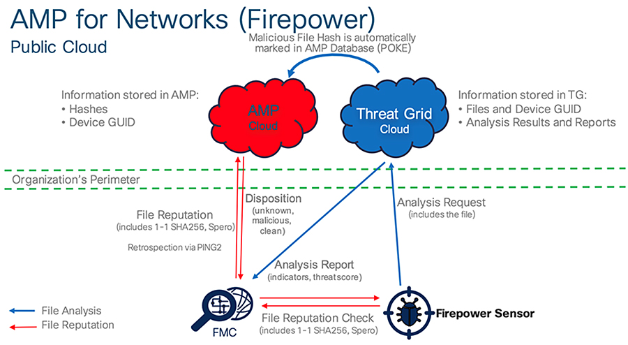
■![]() AMP and Thread Grid deployed on-prem, as an option to be considered on networks with restricted cloud connectivity (AMP and Thread Grid in Private Cloud).
AMP and Thread Grid deployed on-prem, as an option to be considered on networks with restricted cloud connectivity (AMP and Thread Grid in Private Cloud).
Figure 38 AMP and Thread Grid in Private Cloud
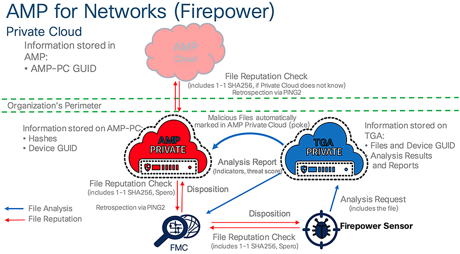
Detect and Respond Use Cases
The following use cases are enabled by Cisco Cyber Vision, ISA 3000, and SecureX in the Industrial Security Design.
Detect a Known CVE and Implement a Firewall Rule
Combining the vulnerability detection of Cisco Cyber Vision with the Cisco Firepower intrusion signatures helps provide specific detection for many Common Vulnerabilities and Exposures (CVEs), allowing the user to better detect relevant threats. The workflow is as follows:
1.![]() A device is connected to the network.
A device is connected to the network.
2.![]() The Cisco Cyber Vision Sensor discovers the device and sends information to Cisco Cyber Vision Center.
The Cisco Cyber Vision Sensor discovers the device and sends information to Cisco Cyber Vision Center.
3.![]() Device characteristics match a rule from Cyber Vision Knowledge DB and alerts of a vulnerability in the device.
Device characteristics match a rule from Cyber Vision Knowledge DB and alerts of a vulnerability in the device.
4.![]() The OT engineer reviews the recommended action, but it cannot be deployed immediately because it can cause downtime. The OT engineer informs an IT engineer of the issue.
The OT engineer reviews the recommended action, but it cannot be deployed immediately because it can cause downtime. The OT engineer informs an IT engineer of the issue.
5.![]() The IT engineer searches in FMC for a rule that matches the vulnerability; if found, the engineer adds it to the intrusion policy and applies it to the ISA 3000.
The IT engineer searches in FMC for a rule that matches the vulnerability; if found, the engineer adds it to the intrusion policy and applies it to the ISA 3000.
Figure 39 Detect a Known Vulnerability and Implement a Firewall Rule
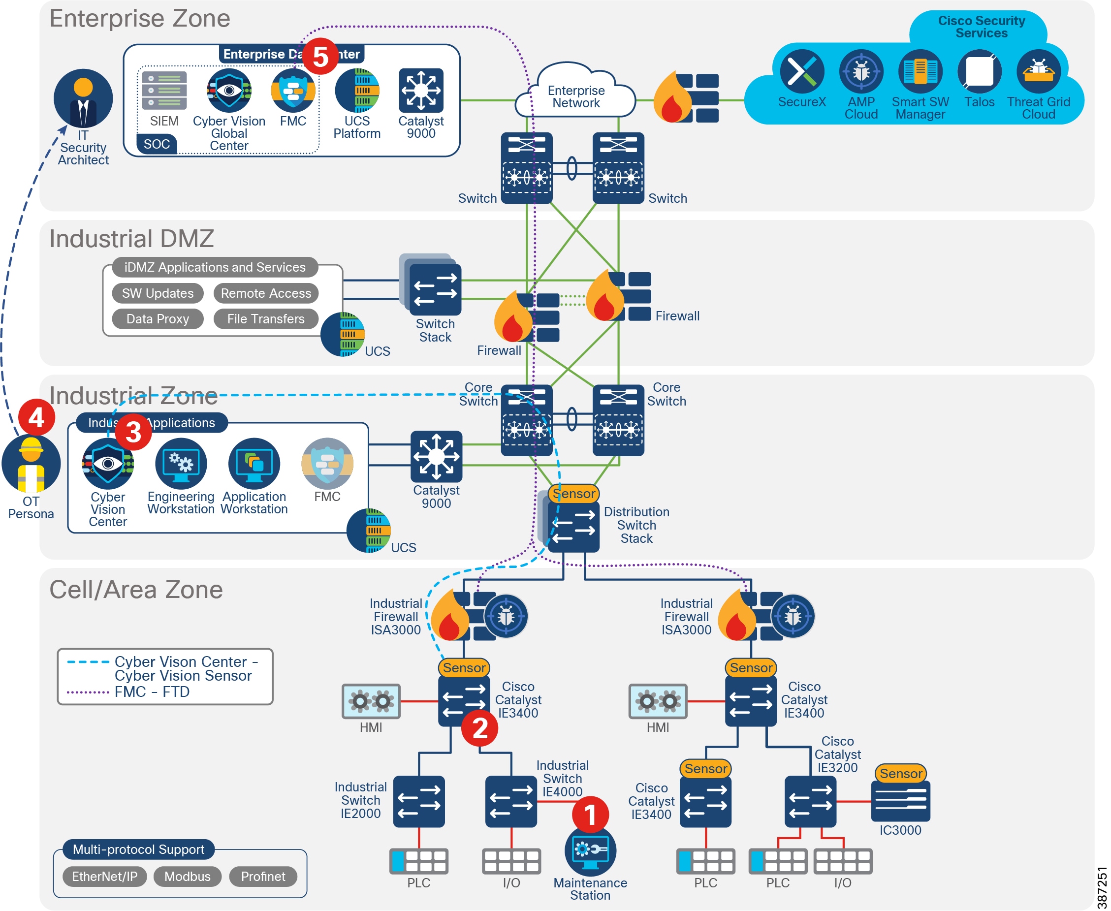
Discover Used Protocols and Block Unused or Unwanted Modes of that Protocol
Limiting unnecessary traffic can help improve network performance and decrease potential avenues for attacks. The baselining feature in Cisco Cyber Vision provides an active monitoring of “normal” operations, which can help highlight any extraneous activity that can be blocked through Firepower ACLs.
1.![]() Cisco Cyber Vision Sensor captures normal flows in the network.
Cisco Cyber Vision Sensor captures normal flows in the network.
2.![]() Cisco Cyber Vision Sensor sends metadata to Cisco Cyber Vision Center.
Cisco Cyber Vision Sensor sends metadata to Cisco Cyber Vision Center.
3.![]() The operator creates a baseline, which shows CIP inter-zone flows. However, no CIP write operations are captured as regular operation activities.
The operator creates a baseline, which shows CIP inter-zone flows. However, no CIP write operations are captured as regular operation activities.
4.![]() An administrator creates an inspection rule in FMC to block CIP writes and adds it to an intrusion policy. An ACL for interzone traffic allowing AppID “CIP/ENIP” is created with action allow and the intrusion policy is associated. They then configure an ACL rule to allow inter-zone traffic for the CIP/ENIP application with the intrusion policy applied.
An administrator creates an inspection rule in FMC to block CIP writes and adds it to an intrusion policy. An ACL for interzone traffic allowing AppID “CIP/ENIP” is created with action allow and the intrusion policy is associated. They then configure an ACL rule to allow inter-zone traffic for the CIP/ENIP application with the intrusion policy applied.
5.![]() The administrator deploys the configuration to the ISA 3000.
The administrator deploys the configuration to the ISA 3000.
Detect and Block a Known Malware
The Cisco Firepower integration with Threat Grid and AMP provides in-depth inspection to detect and block malware. If malware gets into a Cell/Area Zone, ISA 3000 can stop propagation to other zones containing the thread. In addition to that, it provides file trajectory capabilities.
1.![]() An engineer connects a laptop to a switch in the Cell/Area Zone to perform maintenance on a cell controller.
An engineer connects a laptop to a switch in the Cell/Area Zone to perform maintenance on a cell controller.
2.![]() The laptop is infected and begins attacking the network. The ISA 3000 performs file analysis using available tools. Depending on configuration it may do local analysis or cloud lookup.
The laptop is infected and begins attacking the network. The ISA 3000 performs file analysis using available tools. Depending on configuration it may do local analysis or cloud lookup.
3.![]() ISA 3000 gets analysis results and blocks the traffic to avoid spreading to other zones.
ISA 3000 gets analysis results and blocks the traffic to avoid spreading to other zones.
4.![]() ISA 3000 sends intrusion event to FMC. FMC shows a Malware event, and the File Trajectory feature provides useful tracking information for further triage and remediation.
ISA 3000 sends intrusion event to FMC. FMC shows a Malware event, and the File Trajectory feature provides useful tracking information for further triage and remediation.
Figure 40 Detect and Block a Known Malware
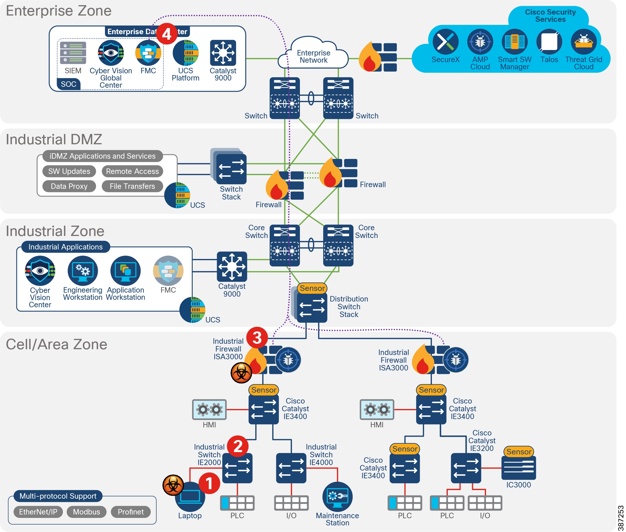
Detect Abnormal Application Flows and Alarm OT
Detecting any and all communications is key to understanding and securing the network. The Cyber Vision baseline feature can help highlight unexpected and potentially malicious activity in the network by monitoring a known good state for any changes. Often times, an infected device starts by scanning the network to identify vulnerable components to attack. This traffic anomaly can be easily identified using Cisco Cyber Vision Monitor Mode.
1.![]() Cisco Cyber Vision Sensor captures normal flows in the network.
Cisco Cyber Vision Sensor captures normal flows in the network.
2.![]() Cisco Cyber Vision Sensor sends metadata to Cisco Cyber Vision Center.
Cisco Cyber Vision Sensor sends metadata to Cisco Cyber Vision Center.
3.![]() An operator creates a baseline of the normal traffic flows.
An operator creates a baseline of the normal traffic flows.
4.![]() An infected device starts scanning the network.
An infected device starts scanning the network.
5.![]() Cisco Cyber Vision Center flags the abnormal behavior.
Cisco Cyber Vision Center flags the abnormal behavior.
6.![]() The operator reviews the anomaly and addresses the behavior.
The operator reviews the anomaly and addresses the behavior.
Cross-launch an Investigation from Cisco Cyber Vision Center
SecureX threat response aggregates and correlates threat intelligence sources and data from multiple security technologies into a single view. It can be used to obtain more information on a particular IP address for an abnormal flow. For example, a network flow to a public IP is detected on Cisco Cyber Vision, it is possible to launch a SecureX investigation from Cisco Cyber Vision Center.
1.![]() A new flow is detected from a baseline—a device is communicating with a public IP address.
A new flow is detected from a baseline—a device is communicating with a public IP address.
2.![]() An operator reviews the anomaly and launches an investigation in SecureX.
An operator reviews the anomaly and launches an investigation in SecureX.
Figure 41 Launch an Investigation on SecureX from Cyber Vision
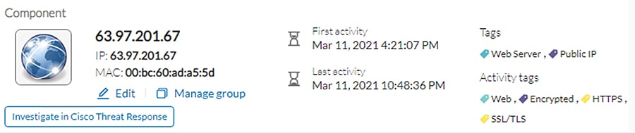
3.![]() An administrator reviews the new incident by checking for IP address reputation and other information available on the public IP. It is concluded that the IP address is secure. Additional investigation shows that IP address is from Cisco Thread Grid.
An administrator reviews the new incident by checking for IP address reputation and other information available on the public IP. It is concluded that the IP address is secure. Additional investigation shows that IP address is from Cisco Thread Grid.
Figure 42 IP Address Investigation
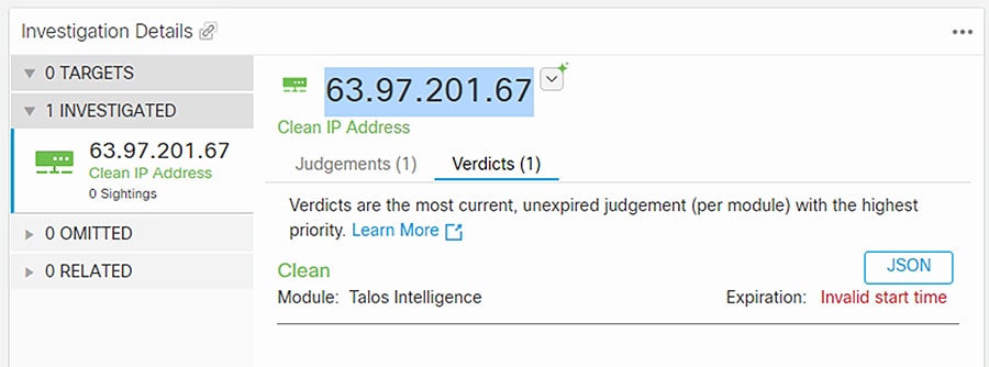
4.![]() Actions are taken to restrict the communication if needed.
Actions are taken to restrict the communication if needed.
Security Events from ISA 3000 are Sent to SecureX
ISA 3000 sends intrusion events to SecureX so they can be correlated with other security sources incidents.
1.![]() ISA 3000 sends intrusion events to SecureX using direct connectivity or syslog proxy.
ISA 3000 sends intrusion events to SecureX using direct connectivity or syslog proxy.
2.![]() An administrator leverages information obtained by ISA 3000 to correlate with data from other security products in the network.
An administrator leverages information obtained by ISA 3000 to correlate with data from other security products in the network.
3.![]() Actions are taken to restrict the communication if needed.
Actions are taken to restrict the communication if needed.
Detect Vulnerabilities in IT Assets and Recommend Mitigation
The Industrial network includes numerous devices and operating systems, including traditional IT assets such as laptops. FMC uses the network discovery policy to obtain information about hosts in the network and it is able to detect vulnerabilities on components. When ISA 3000 detects an intrusion event, FMC correlates the information with known hosts. As a result, FMC can display intrusion events flagged with an impact flag that is used to evaluate criticality. For example, if the intrusion occurs in a host belonging to the internal network and is a vulnerable host it displays a red flag for immediate attention.
Appendix A—Comparison of Cisco Cyber Vision, Cisco Industrial Network Director, and Cisco Stealthwatch
The security for an industrial network covers various aspects and Cisco’s approach is to provide a full spectrum of coverage. Cisco offers Cisco Cyber Vision, Cisco Industrial Network Director, and Cisco Stealthwatch, which are complementary technologies that, with Cisco Identity Services Engine, provide an effective combination for broad coverage.
Cisco Stealthwatch covers malware, zero-day worms, and other enterprise IT threats.
Appendix B—SCADA Preprocessors Rules
Modbus Preprocessor Rules
DNP3 Preprocessor Rules
CIP Preprocessor Rules
|
|
|
|
|
|
|
|
|
|
|
|
|
|
|
S7Commplus Preprocessor Rules
|
|
|
|
|
|
|
|
|
|
|
|
Appendix C—SCADA Preprocessors Configuration Options
|
|
|
|
|
|
|
|
|
|
|
|
|
|
|
|
|
|
|
■ ■ |
|
|
|
|
|
|
|
|
|
|
|
|
Note: You must add the default CIP detection port 44818 and any other CIP Ports you list to the TCP stream Perform Stream Reassembly on Both Ports list.
Appendix D—System-Provided Variables
Appendix E—Sensor Deployment Option Using RSPAN
There is an additional option to enable Cisco Cyber Vision sensors on the network, but it is not generally recommended since it can multiply the amount of traffic on links. For this option, enable RSPAN on all the switches and direct the monitored traffic to the switch where a hardware or network sensor is installed. RSPAN option requires a single sensor and no monitoring network, but this option may multiply the traffic in the network by duplicating the mirrored traffic in every port.
Figure 43 Sensor Deployment Option Using RSPAN
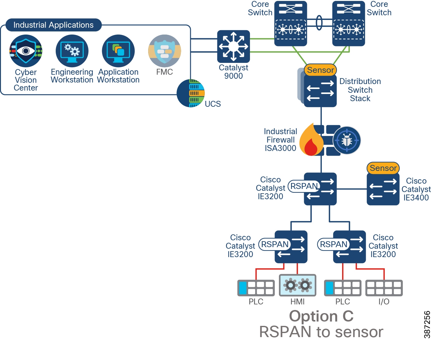
 Feedback