Cisco Multicloud Defense Architecture Guide
Available Languages
Bias-Free Language
The documentation set for this product strives to use bias-free language. For the purposes of this documentation set, bias-free is defined as language that does not imply discrimination based on age, disability, gender, racial identity, ethnic identity, sexual orientation, socioeconomic status, and intersectionality. Exceptions may be present in the documentation due to language that is hardcoded in the user interfaces of the product software, language used based on RFP documentation, or language that is used by a referenced third-party product. Learn more about how Cisco is using Inclusive Language.
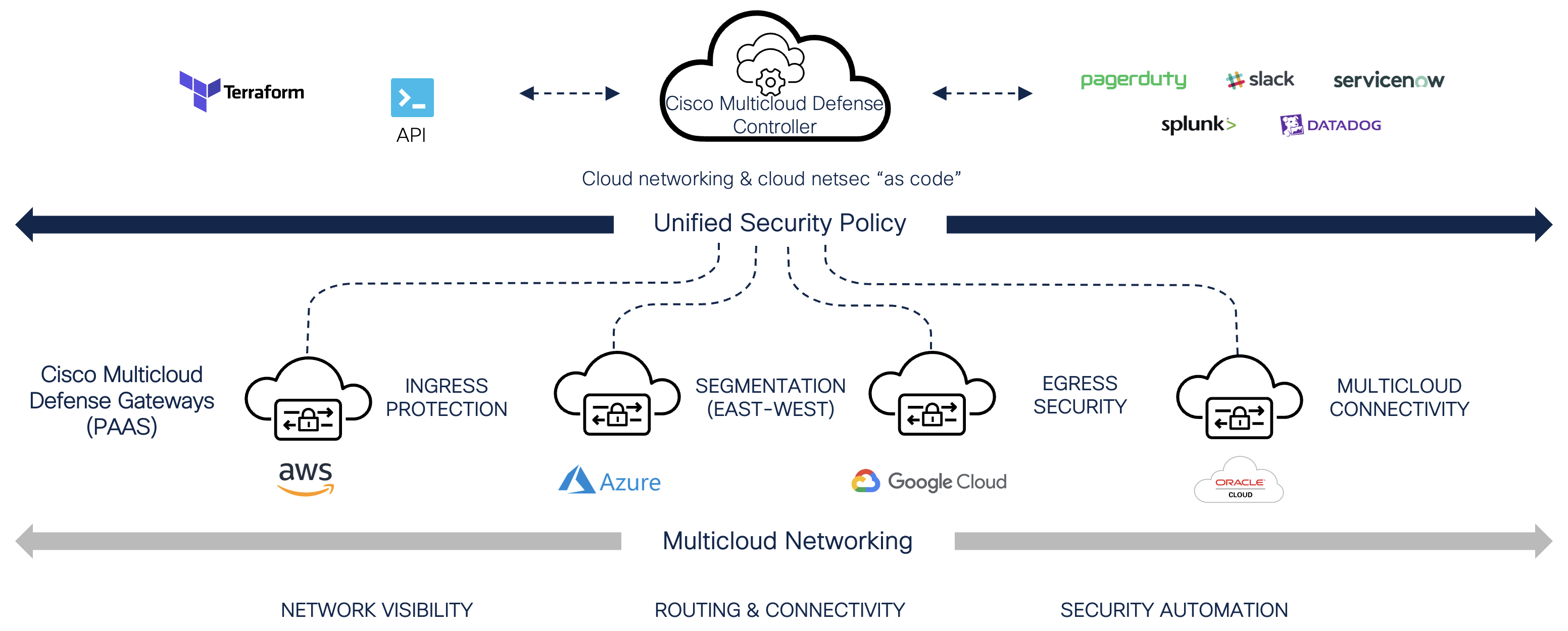
The Cisco Multicloud Defense Architecture Guide provides Reference Architecture diagrams of how the Cisco Multicloud Defense solution is deployed within each Cloud Provider and for each security use-case. These diagrams describe the architectural deployment scenarios available to address different security requirements. Cisco Multicloud Defense simplifies cloud security by orchestrating the deploy and management of advanced workload protection. The reference architectures are intended to provide users with information on how Cisco Multicloud Defense is deployed and are not intended for manual configuration.
The Cisco Multicloud Defense solution is made up of a set of components: Controller/UI, Gateway and Terraform Provider. The Cisco Multicloud Defense Controller/UI is a SaaS delivered component that is managed and maintained by Cisco. The Multicloud Defense Gateways are a PaaS component that is deployed within the customer Cloud Service Provider (CSP) account/subscription/project and managed through Cisco Defense Orchestrator. The Multicloud Defense Gateways are orchestrated and managed by the CDO using either the Multicloud Defense UI or the Multicloud Defense Terraform Provider. The Reference Architectures will primarily focus on how the Multicloud Defense Gateways are deployed to protect cloud workloads.
Cisco Multicloud Defense
In a centralized ingress deployment, a Service VPC will be used as a centralized security hub to connect all spoke VPCs and route traffic using an AWS Transit Gateway (TGW). Multicloud Defense will orchestrate the deployment of the Service VPC and attach the Service VPC to an existing or new TGW (orchestrated by Multicloud Defense). The Service VPC will use an AWS Network Load Balancer (NLB) as the destination for all ingress traffic. The NLB will load balance the traffic across one or more Multicloud Defense Gateway instances deployed to accommodate protection. The Multicloud Defense Gateway will act as a Reverse Proxy to inspect and protect northbound traffic destined for applications and workloads.
Deployment Architecture – AWS Centralized Ingress
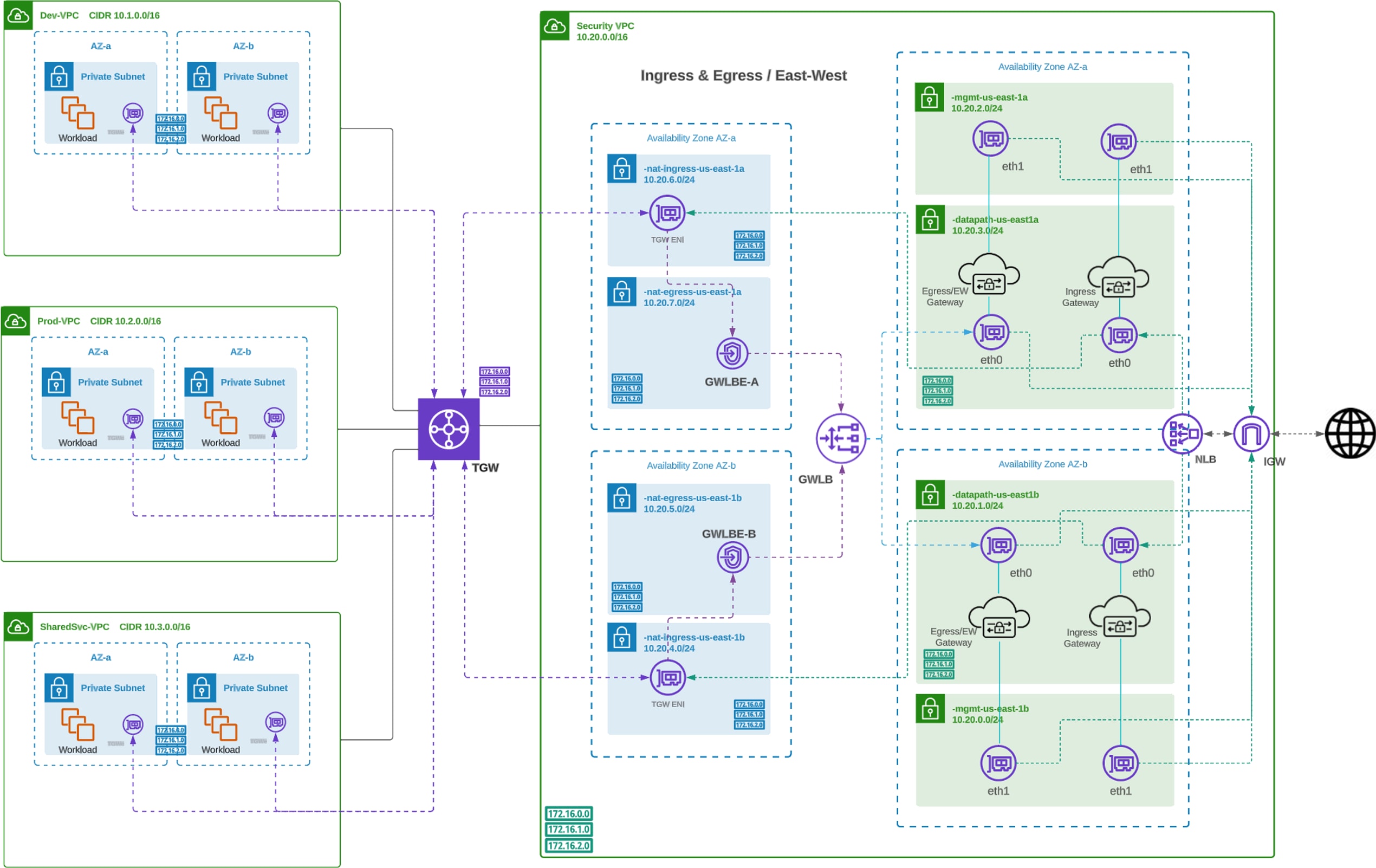
Centralized Ingress Deployment Architecture (AWS)
Traffic Flow – AWS Centralized Ingress
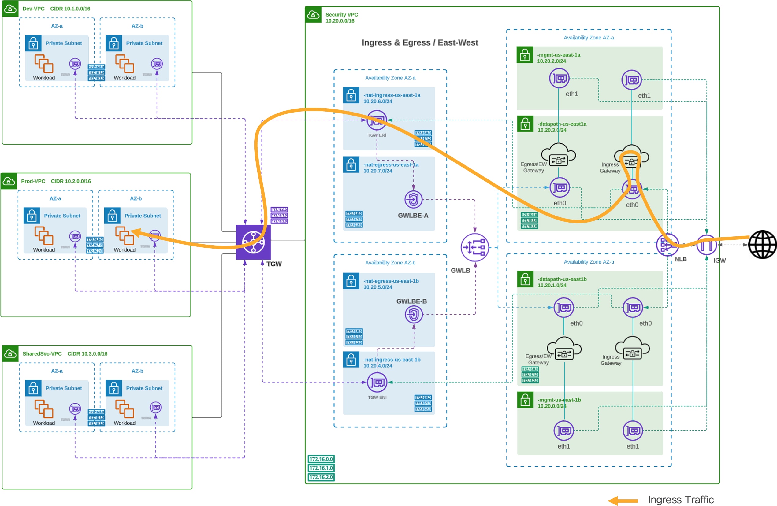
Centralized Ingress Traffic Flow (AWS)
Routing Configuration - AWS Centralized Ingress
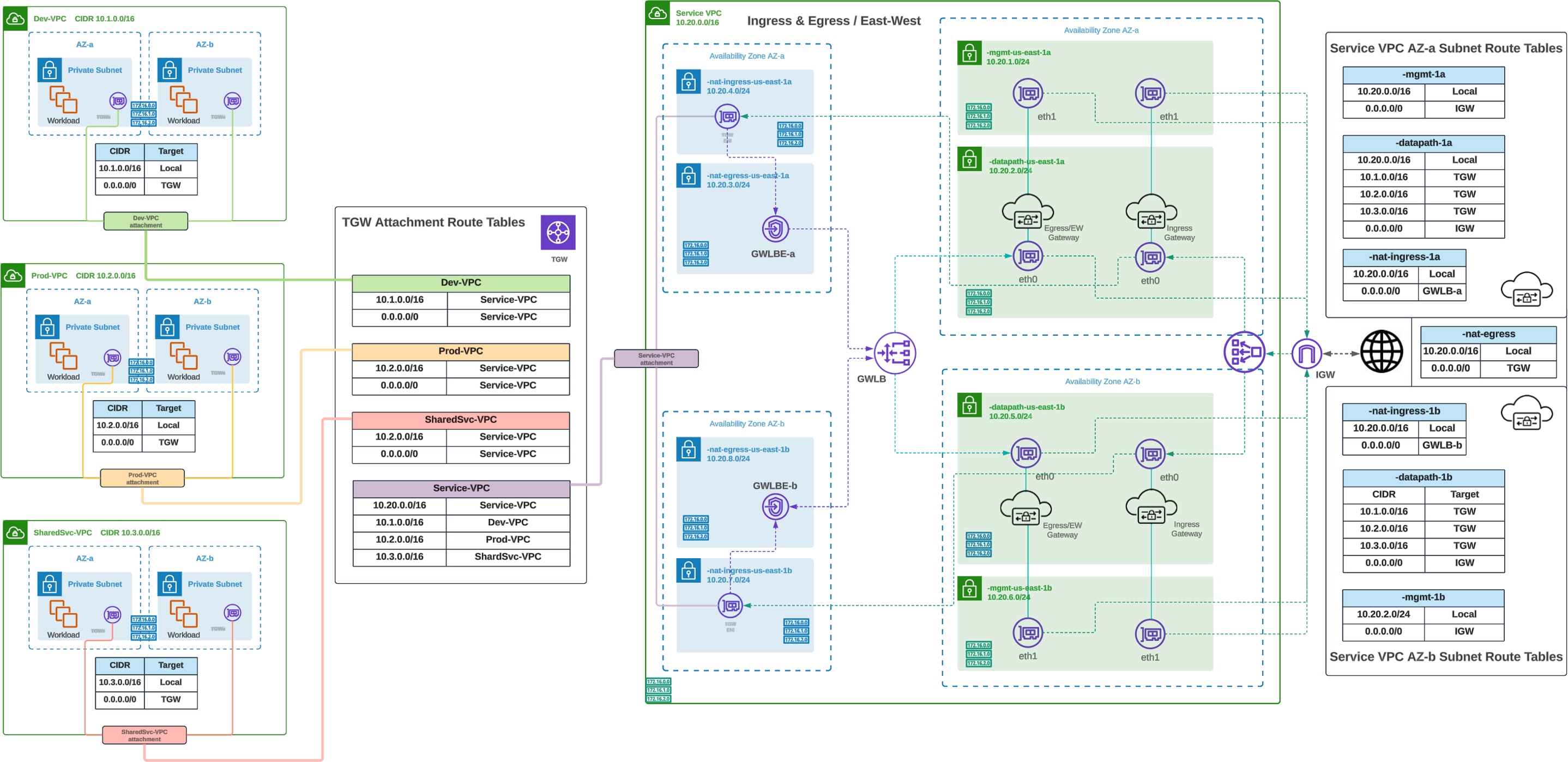
Centralized Ingress Routing Configuration (AWS)
Note: The diagram shows both Ingress and Egress / East-West Gateways. The Ingress and Egress / East-West Gateways can be deployed into the same VPC. If protection is for Ingress only, the Egress / East-West Gateway is not needed.
In a centralized Egress deployment, a Service VPC will be used as a centralized security hub to connect all spoke VPCs and route traffic using an AWS Transit Gateway (TGW). Multicloud Defense will orchestrate the deployment of the Service VPC and attach the Service VPC to an existing or new TGW (orchestrated by Multicloud Defense). The Service VPC will use an AWS Gateway Load Balancer (GWLB). The GWLB will load balance the traffic across one or more Multicloud Defense Gateway instances deployed to accommodate protection. The Multicloud Defense Gateway will operate in Forwarding or Forward Proxy to inspect and protect southbound and east-west traffic.
Deployment Architecture – AWS Centralized Egress
Refer to Figure 2 for a diagram of Centralized Egress Deployment Architecture (AWS).
Traffic Flow – AWS Centralized Egress
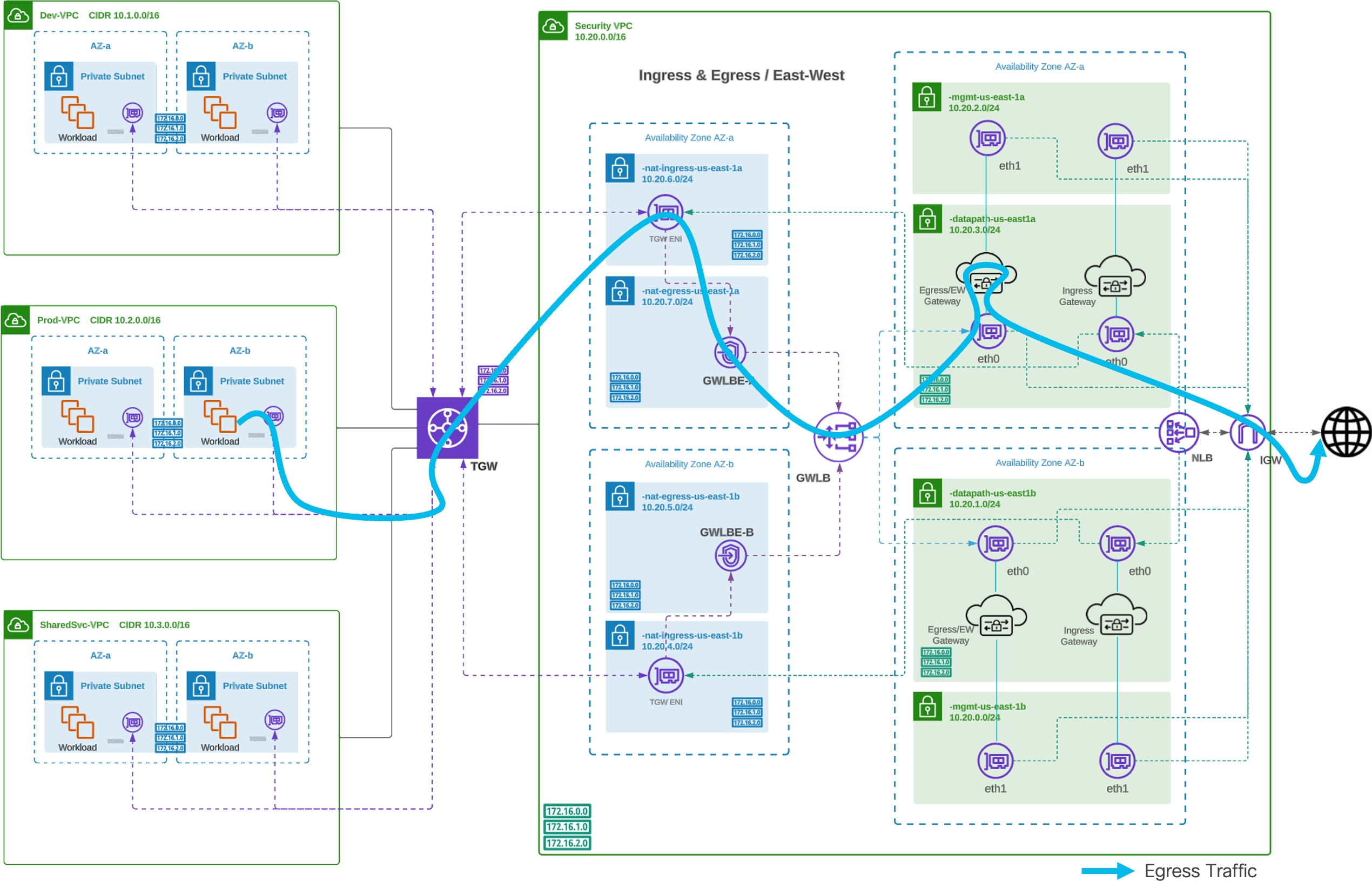
Centralized Egress Traffic Flow - Egress (AWS)
Routing Configuration – AWS Centralized Egress
Refer to Figure 4 for a diagram of Centralized Egress Routing Configuration (AWS).
Note: The diagram shows both Ingress and Egress / East-West Gateways. The Ingress and Egress / East-West Gateways can be deployed into the same VPC. If protection is for Egress /East-West only, the Ingress Gateway is not needed.
In a centralized East-West deployment, a Service VPC will be used as a centralized security hub to connect all spoke VPCs and route traffic using an AWS Transit Gateway (TGW). Multicloud Defense will orchestrate the deployment of the Service VPC and attach the Service VPC to an existing or new TGW (orchestrated by Multicloud Defense). The Service VPC will use an AWS Gateway Load Balancer (GWLB). The GWLB will load balance the traffic across one or more Multicloud Defense Gateway instances deployed to accommodate protection. The Multicloud Defense Gateway will operate in Forwarding or Forward Proxy to inspect and protect southbound and east-west traffic.
Deployment Architecture – AWS Centralized East-West
Refer to Figure 2 for a diagram of Centralized East-West Deployment Architecture (AWS).
Traffic Flow – AWS Centralized East-West, Inter-VPC
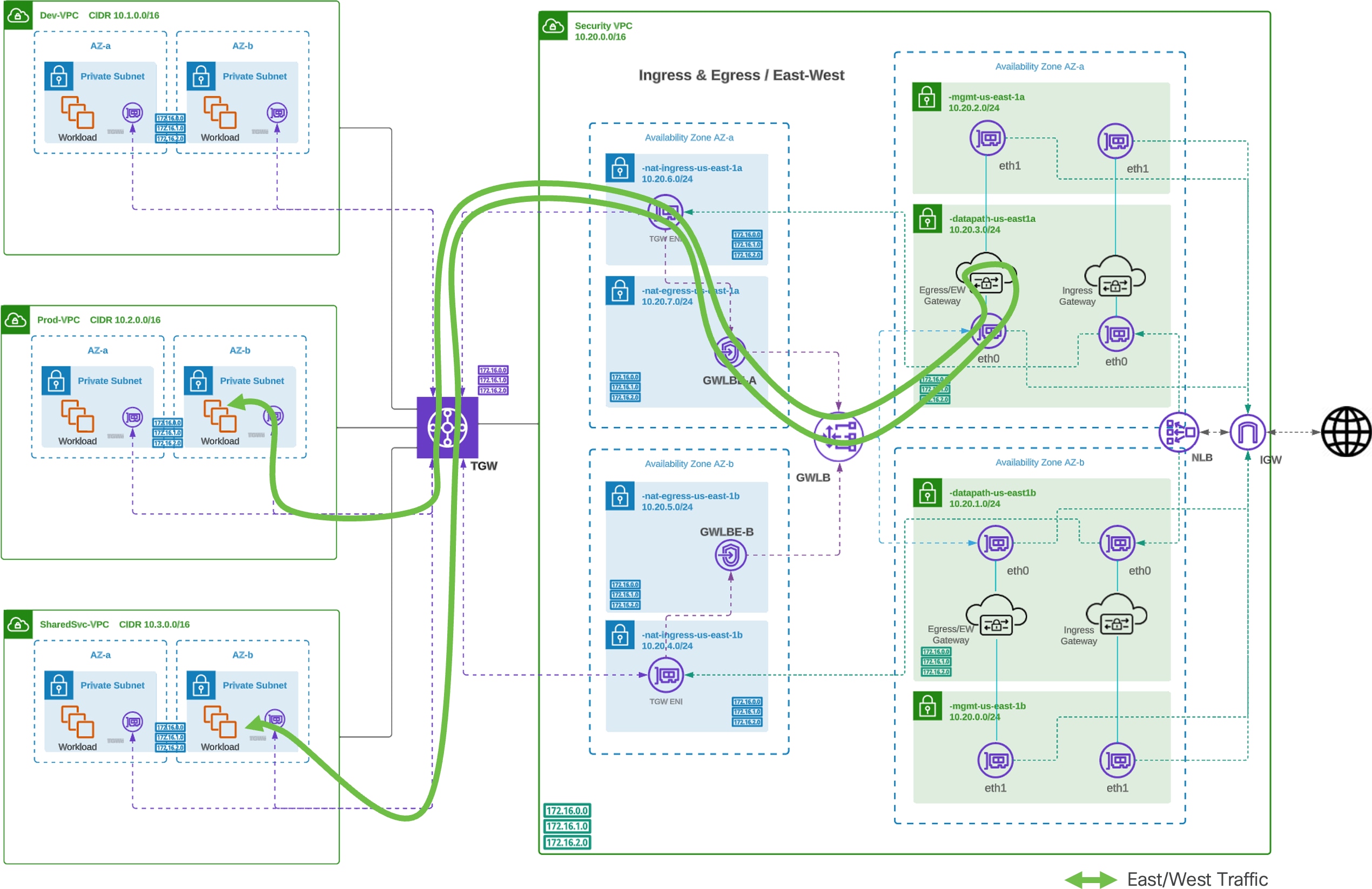
Traffic Flow Centralized East-West, Inter-VPC (AWS)
Traffic Flow – AWS Centralized East-West, Intra- VPC
Traffic Flow Centralized East-West, Intra-VPC (AWS)
Routing Configuration – AWS Centralized East-West
Refer to Figure 4 for a diagram of Centralized East-West Routing Configuration (AWS).
Note: The diagram shows both Ingress and Egress / East-West Gateways. The Ingress and Egress / East-West Gateways can be deployed into the same VPC. If protection is for Egress /East-West only, the Ingress Gateway is not needed.
AWS Centralized East-West with More Specific Routing (MSR)
The advent of More Specific Routing (MSR) in AWS allow for traffic communicating between subnets within a VPC to be inspected by Multicloud Defense. Multicloud Defense uses the Service VPC as the security hub and placement of a Gateway Load Balancer (GWLB) Endpoint into the Spoke VPC to route traffic to the Service VPC. The route table for each subnet would have MSR configured to route traffic through the Endpoint to the Service VPC for inspection.
Deployment Architecture and MSR Configuration
AWS Centralized MSR Configuration
AWS Centralized Egress / East-West (NAT Gateway)
When using Multicloud Defense to protect Egress traffic, traffic sent to the Internet will have a source IP of the Multicloud Defense Gateway instance. If there is a need for the Gateway instances to be deployed as private, and the IP address used to send traffic to the Internet needs to be static (does not change), the Service VPC can be deployed using a NAT Gateway. When the NAT Gateway option is enabled, the Multicloud Defense Gateway is deployed into private subnets and public subnets will be created to host the NAT Gateways (per AZ). All traffic to the Internet will be sent from the Gateway instances through the NAT Gateways using the NAT Gateway public IP addresses. This allows the IP address of the NAT Gateways to be whitelisted, which is often required when interfacing a cloud resource to a SaaS-delivered Identity Provider for authentication.
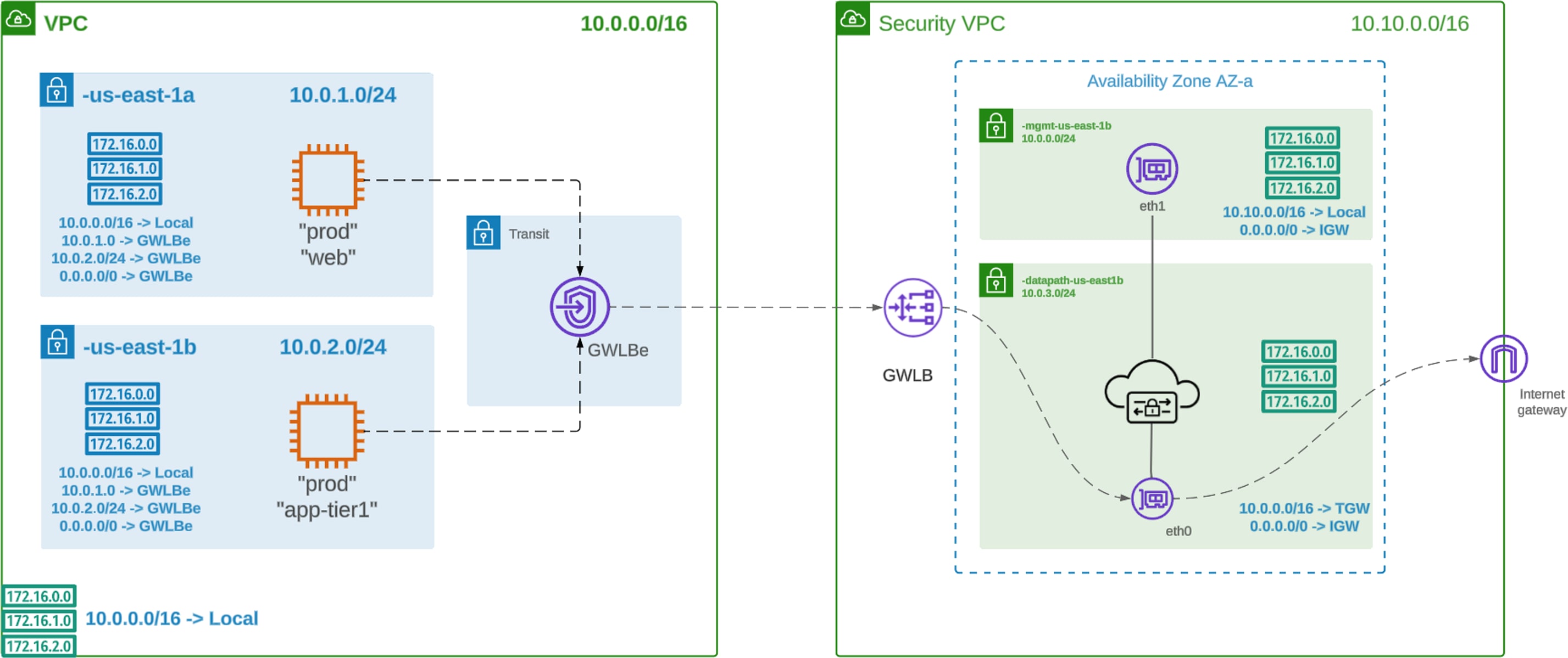
Deployment Architecture – AWS Centralized Egress/East-West
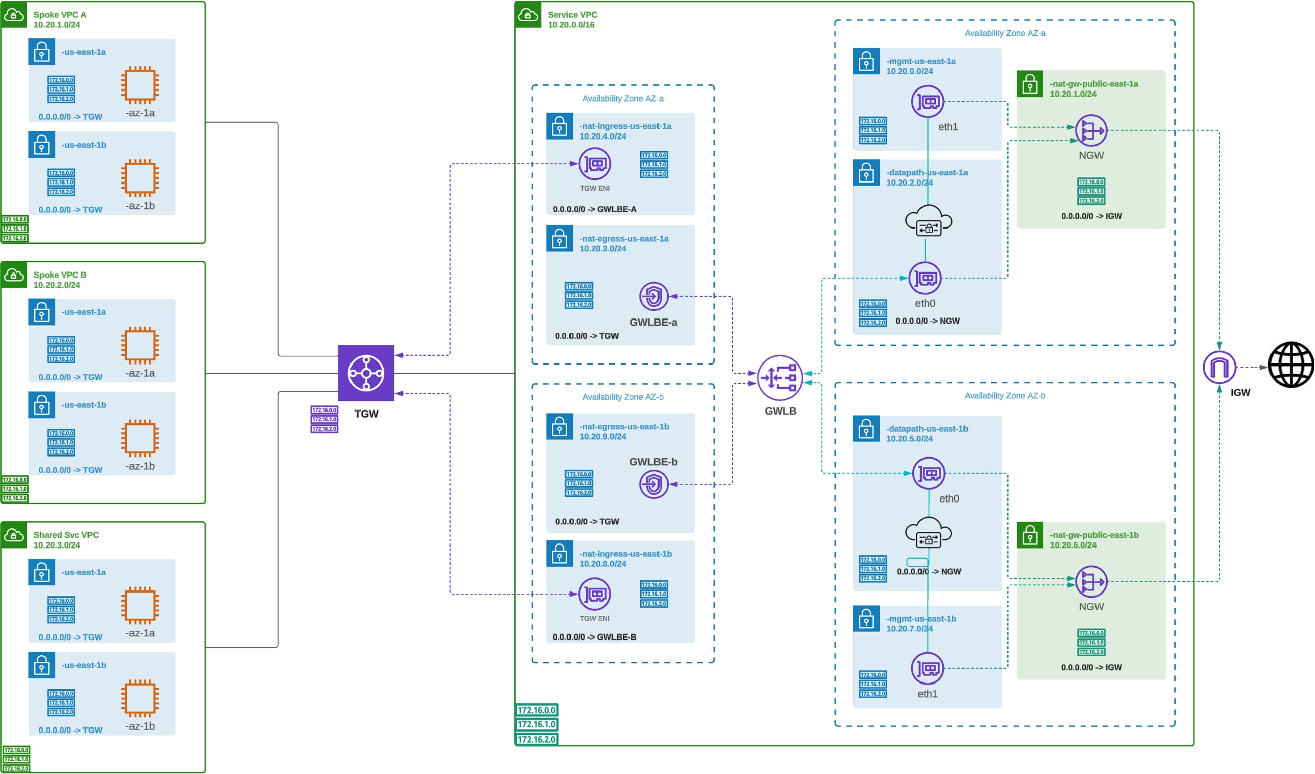
AWS Centralized Egress / East-West (NAT Gateway) – Deployment Architecture
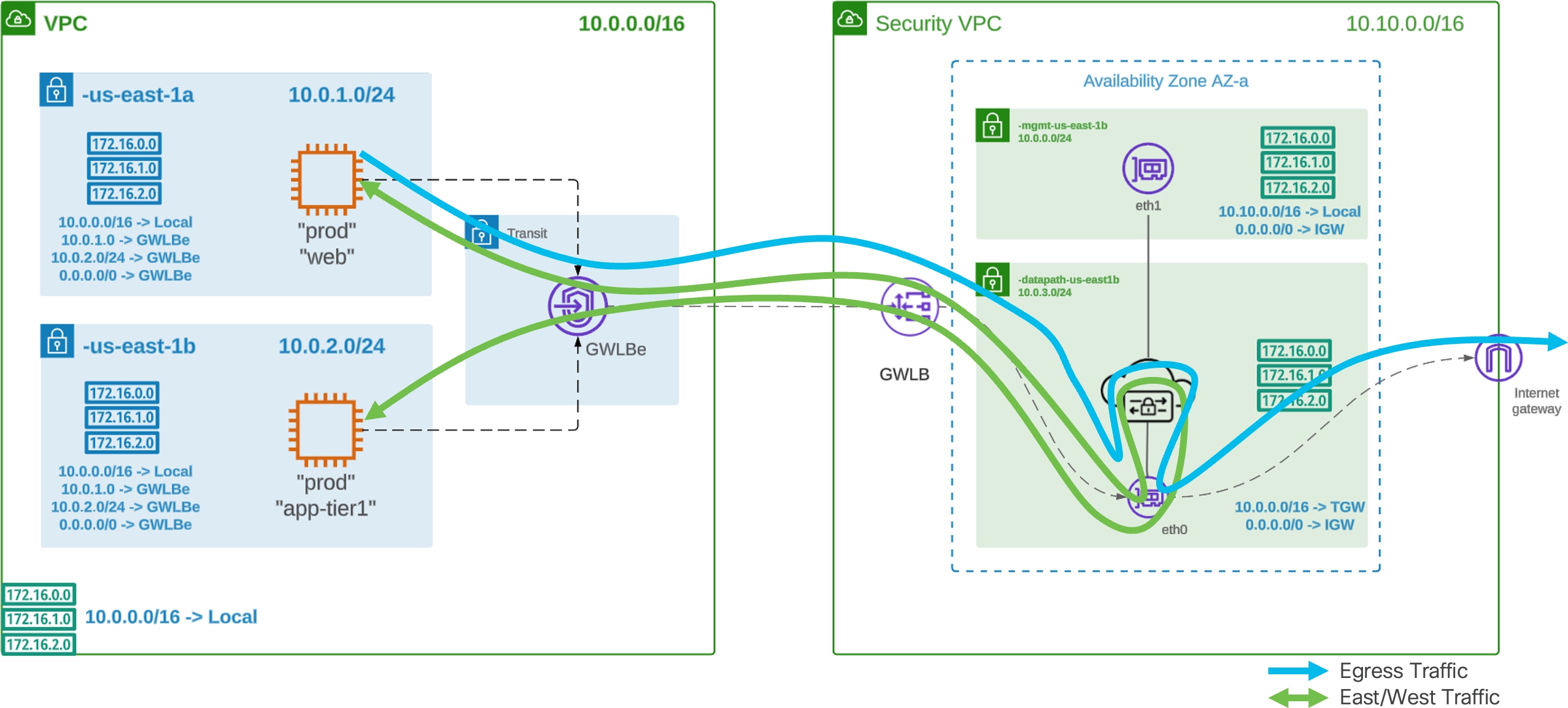
Traffic Flow – AWS Centralized Egress/East-West
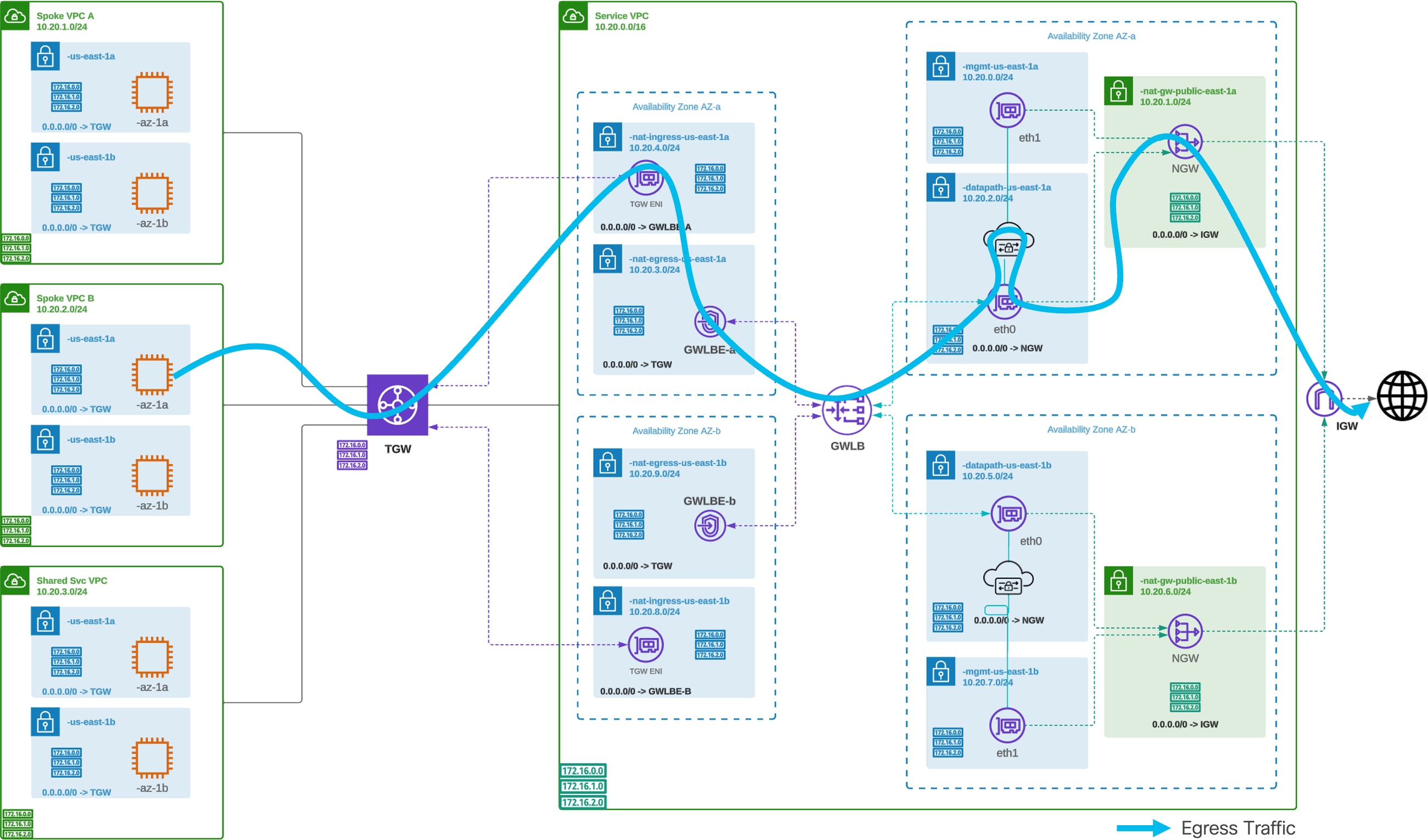
AWS Centralized Egress / East-West (NAT Gateway) – Traffic Flow
Routing Configuration – AWS Centralized Egress/East-West
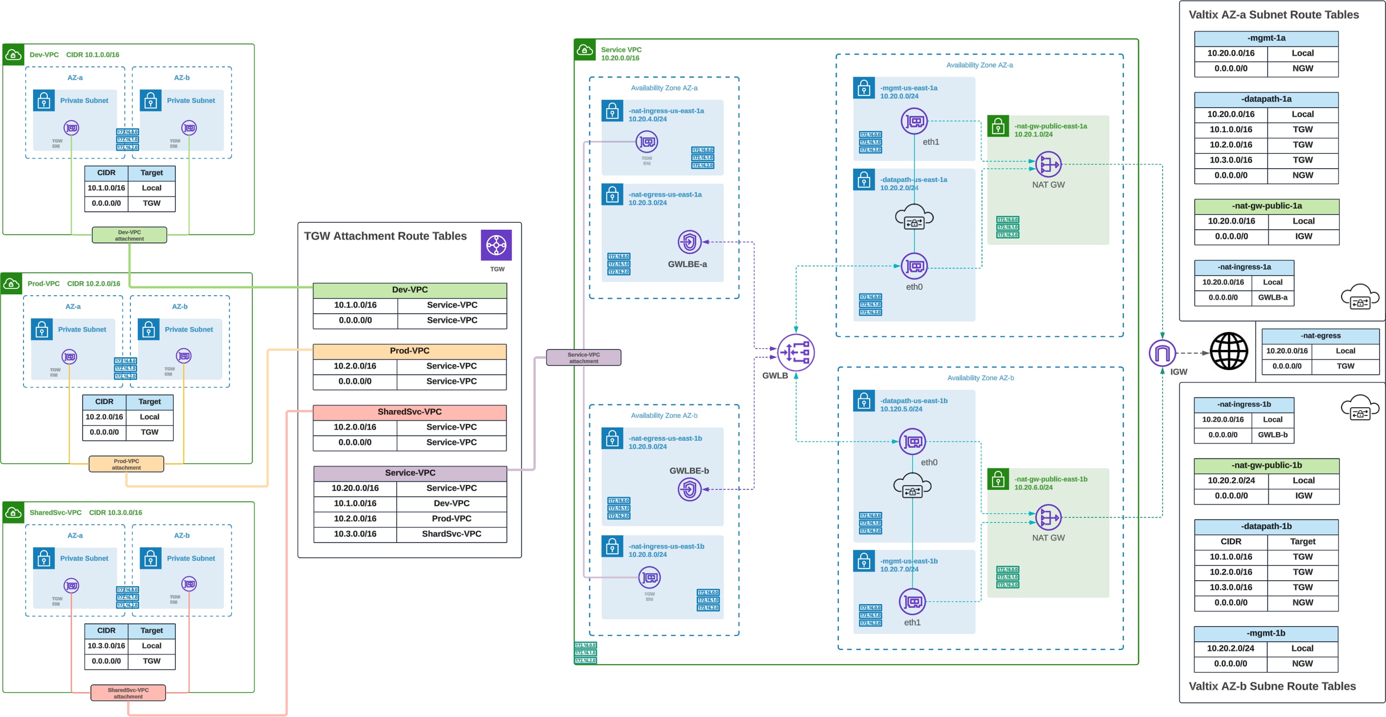
AWS Centralized Egress / East-West (NAT Gateway) – Routing Configuration
AWS Centralized GWLB-based Ingress / Egress
In a centralized GWLB-based ingress and egress deployment, a Service VPC will be used as a centralized security hub to connect all spoke VPCs and route traffic using a Gateway Load Balancer (GWLB) and GWLB Endpoints. Multicloud Defense will orchestrate the deployment of the Service VPC, Service VPC infrastructure, Gateways and the GWLB. The GWLB Endpoints in the Spoke VPCs, used to connect to the GWLB, will need to be orchestrated by the user (AWS Console or Terraform). The GWLB Endpoints will be used to pass traffic to Multicloud Defense. The GWLB will load balance the traffic across one or more Multicloud Defense Gateway instances. The Multicloud Defense Gateway will Forward or Forward Proxy the traffic to inspect and protect north- and south-bound traffic destined for applications and workloads, or the Internet.
Routing Configuration – AWS Centralized GWLB-based Ingress/Egress
Refer to Figure 11 for a diagram of AWS Centralized GWLB-based Ingress / Egress – Routing Configuration.
In Centralized Ingress model, Multicloud Defense would orchestrate a Service VNet and create a VNet peering between the Spoke VNet and Service VNet. Multicloud Defense will create User Defined Routes (UDR) in Spoke VNets to have traffic routed to the Service VNet. All necessary component inside the Service VNet(Multicloud Defense Gateway, Network Security Group, NLB) will be created and managed by Multicloud Defense. The NLB would be a public endpoint to receive internet traffic and load balanced to Multicloud Defense Gateways. Multicloud Defense Gateways will act as a reverse proxy and protect your workloads.
Deployment Architecture – Azure Centralized Ingress
Azure Centralized Ingress - Deployment Architecture
Note: The diagram shows both Ingress Gateway and Egress+East-West Gateway. User can choose to deploy Ingress and Egress+East-West Gateway in the same VPC. If protection is for Ingress only, deployment of Egress Gateway is not needed.
Traffic Flow – Azure Centralized Ingress
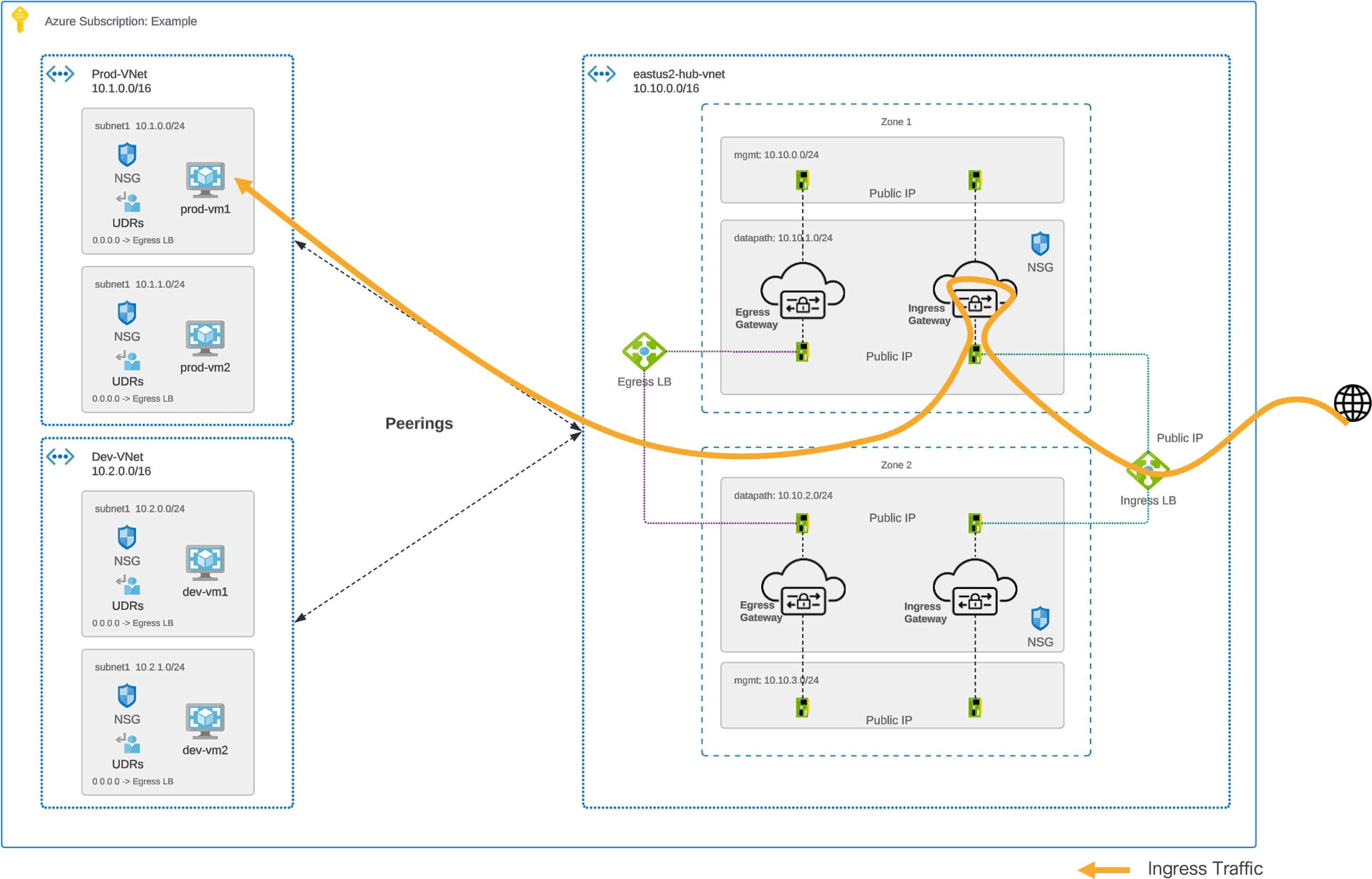
Azure Centralized Ingress – Traffic Flow
Routing Configuration – Azure Centralized Ingress
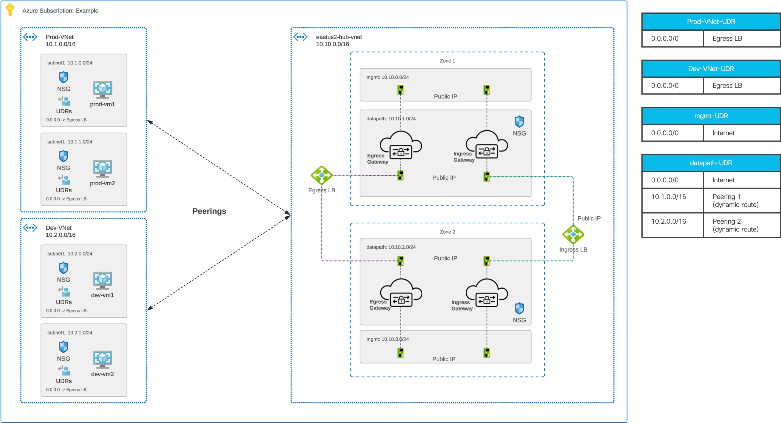
Azure Centralized Ingress - Routing Configuration
Multicloud Defense orchestrate a Service VNet in a centralized model where the Service VNet will act as the enforcement hub. A VNet peering would be created between the Spoke VNet and the Service VNet. Multicloud Defense will create/update User Defined Routes(UDR) in Spoke VNets to have traffic routed to the Service VNet. Inside the Service VNet, there would be a Network Load Balancer(NLB) and Multicloud Defense Gateway. Traffic from Spoke VNet would be routed to the NLB, which would then be load balanced between Multicloud Defense Gateways in multiple Availability Zones.
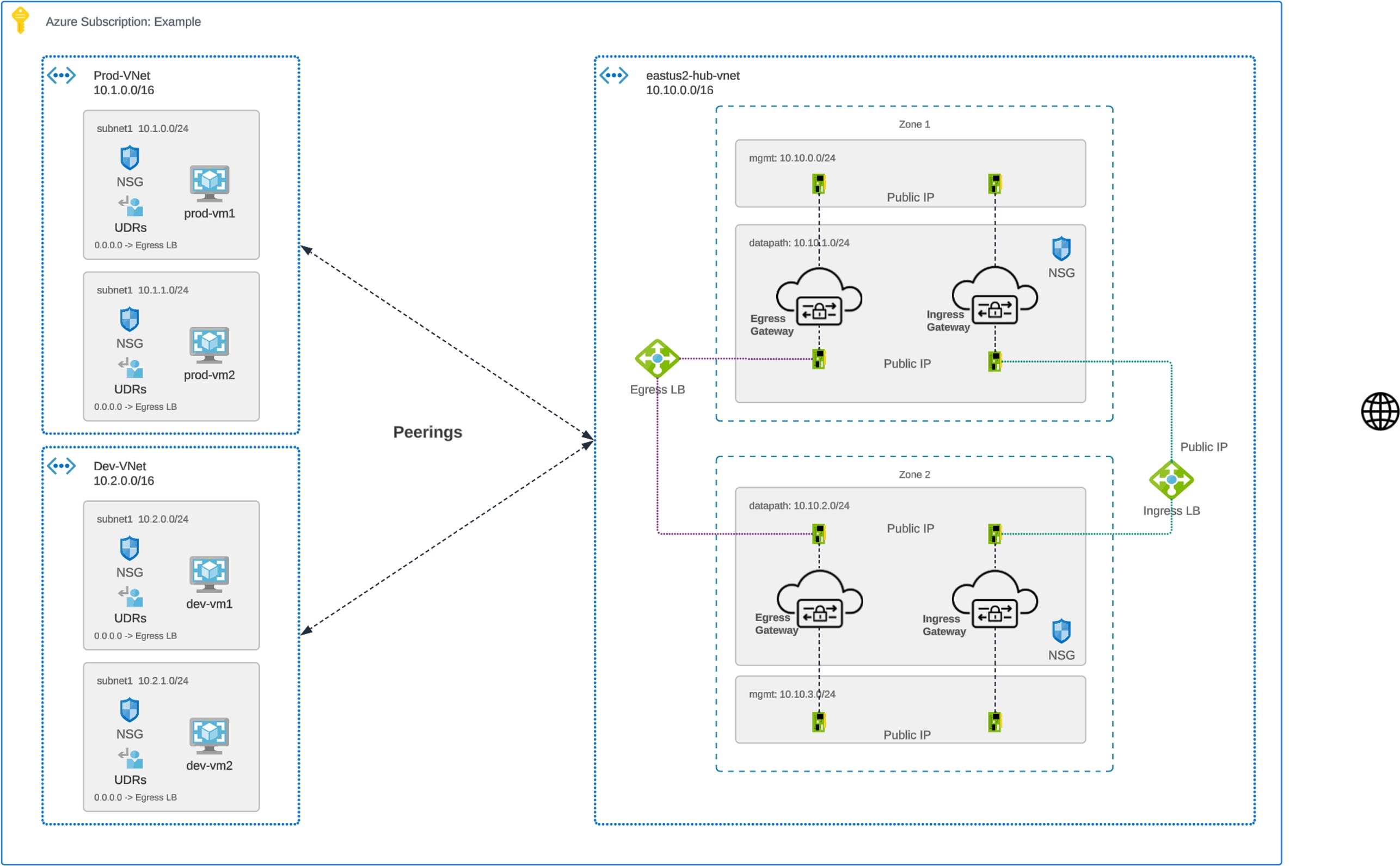
Deployment Architecture – Azure Centralized Egress
Refer to Figure 12 for a diagram of Azure Centralized Egress - Deployment Architecture.
Note: The diagram shows both Ingress Gateway and Egress+East-West Gateway. User can choose to deploy Ingress and Egress+East-West Gateway in the same VPC. If protection is for Egress/East-West only, deployment of Ingress Gateway is not needed.
Traffic Flow – Azure Centralized Egress
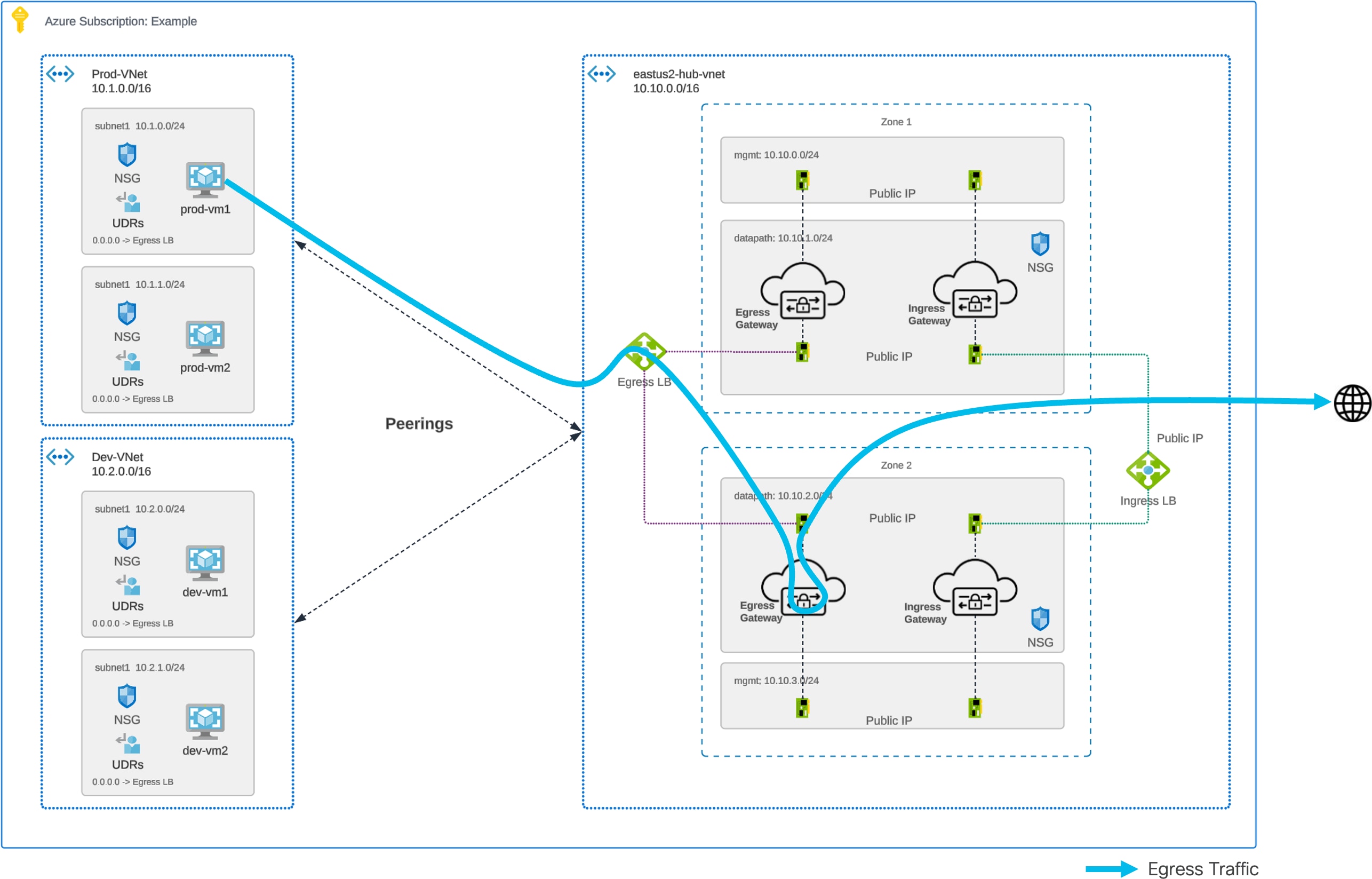
Azure Centralized Egress – Traffic Flow
Routing Configuration – Azure Centralized Egress
Refer to Figure 14 for a diagram of Azure Centralized Egress - Routing Configuration.
Deployment Architecture – Azure Centralized East-West
Refer to Figure 12 for a diagram of Azure Centralized East-West - Deployment Architecture.
Traffic Flow – Azure Centralized East-West
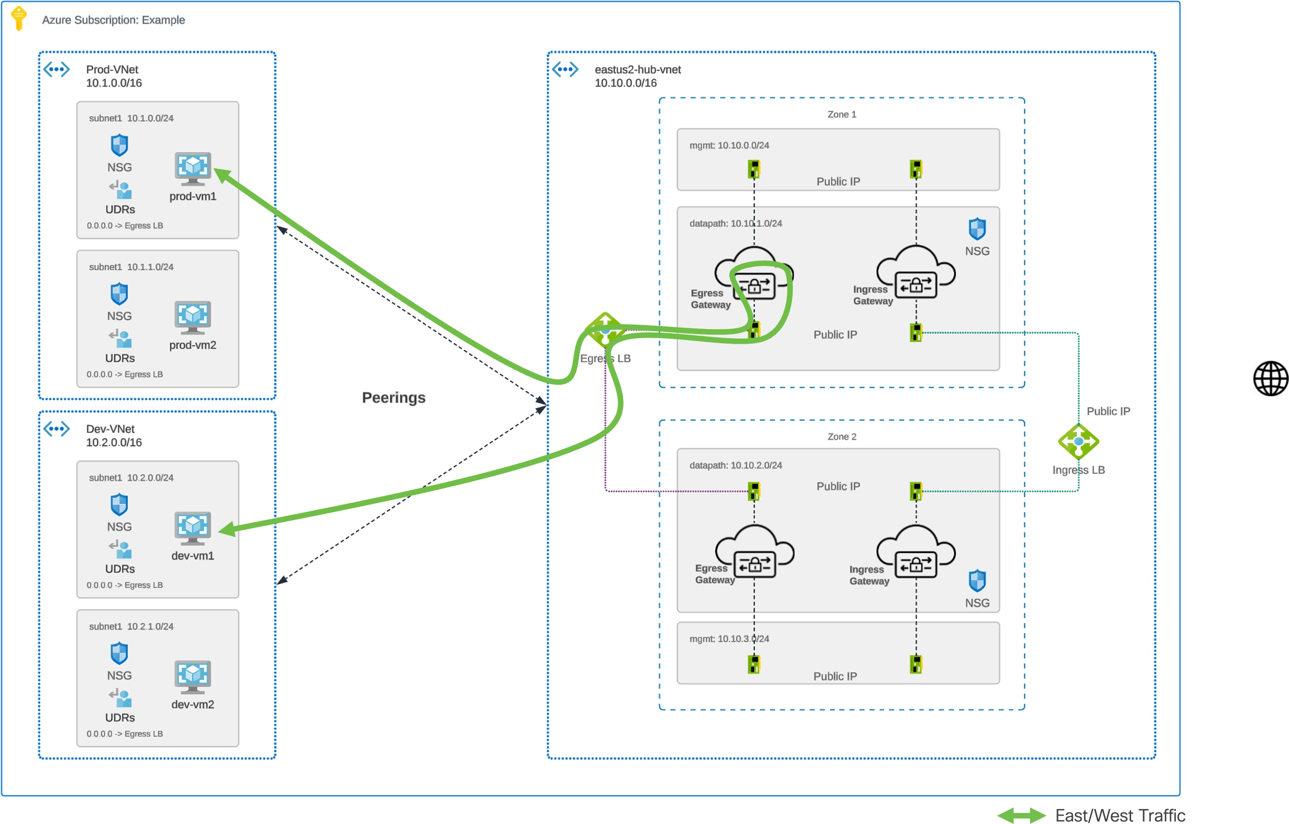
Azure Centralized East-West - Traffic Flow
Routing Configuation – Azure Centralized East-West
Refer to Figure 14 for a diagram of Azure Centralized East-West - Routing Configuration.
Multicloud Defense's Centralized Security in GCP is achieved by deploying a VPC (called Security VPC or Service VPC) for all security components and perform a VPC Peering between the Security VPC and all spoke VPCs. Multicloud Defense orchestrates the Service VPC (and all necessary component) to protect all type of traffic (ingress, egress, and east-west). Inside the Service VPC, there would be two (2) gateways, one for ingress and one for egress/east-west. Multicloud Defense can also orchestrate the VPC peering between Service VPC and all Spoke VPCs by a simple click of a button.
Deployment Architecture – GCP Centralized Ingress
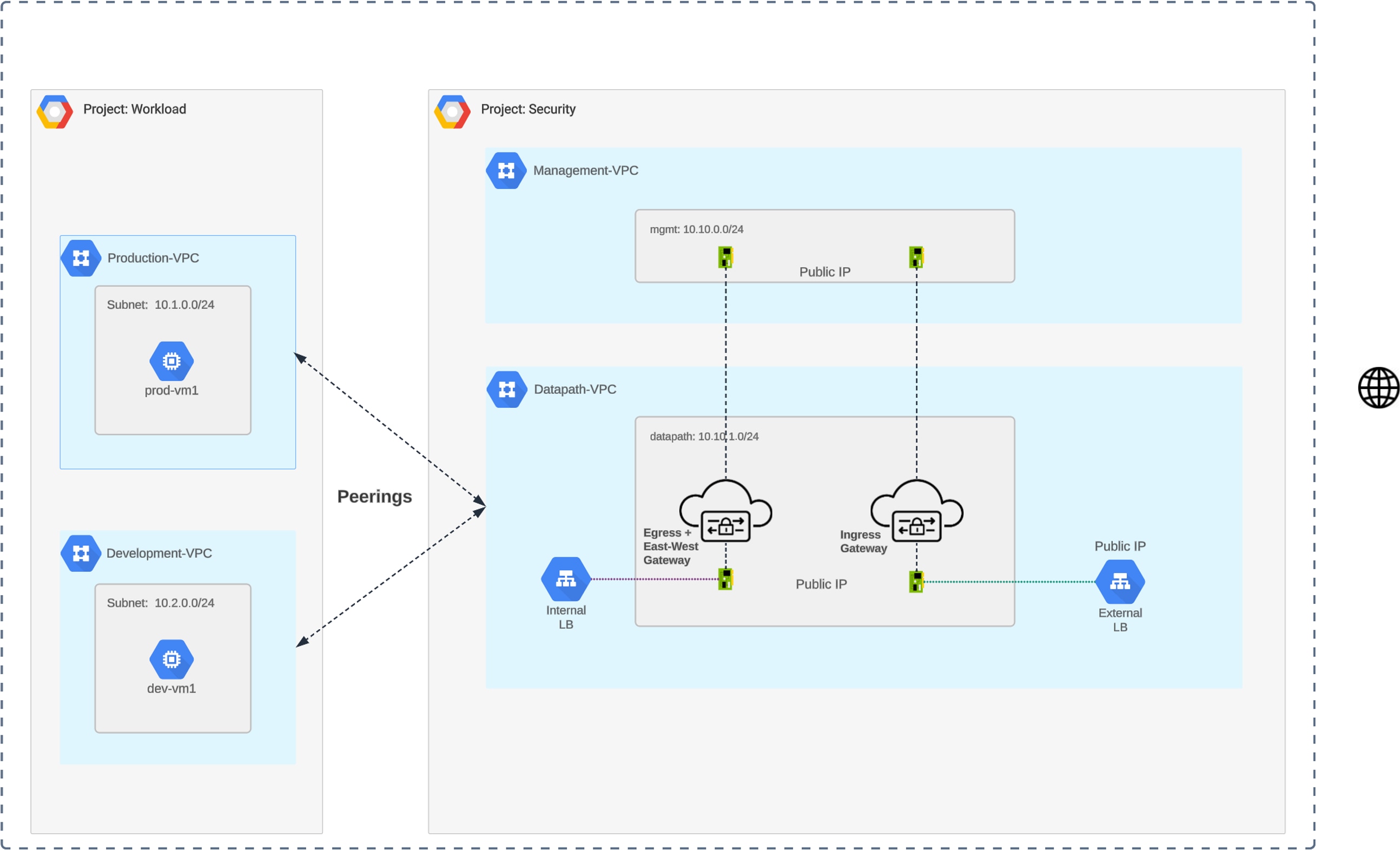
GCP Centralized Ingress – Deployment Architecture
Traffic Flow – GCP Centralized Ingress
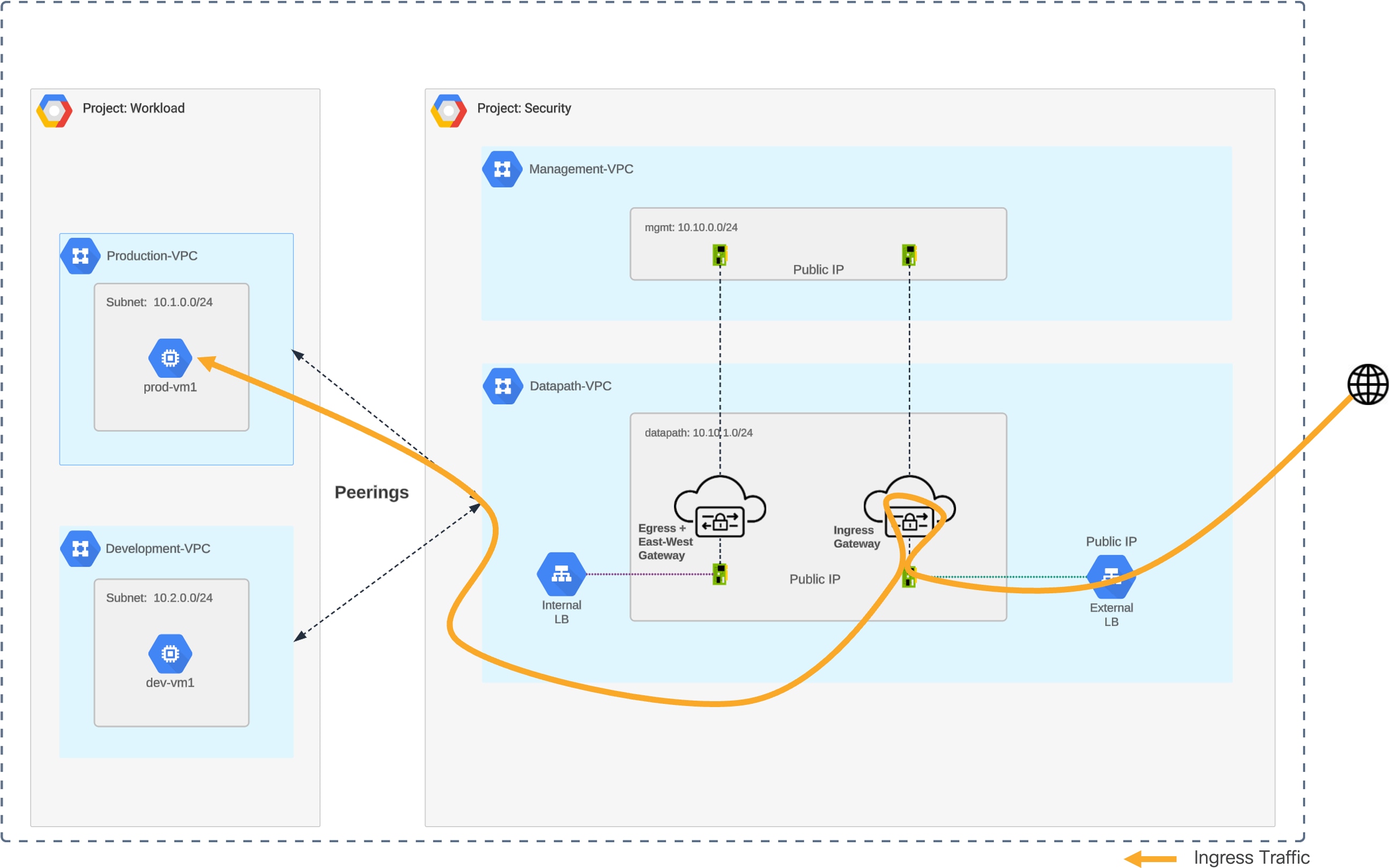
GCP Centralized Ingress – Traffic Flow
Routing Configuration – GCP Centralized Ingress
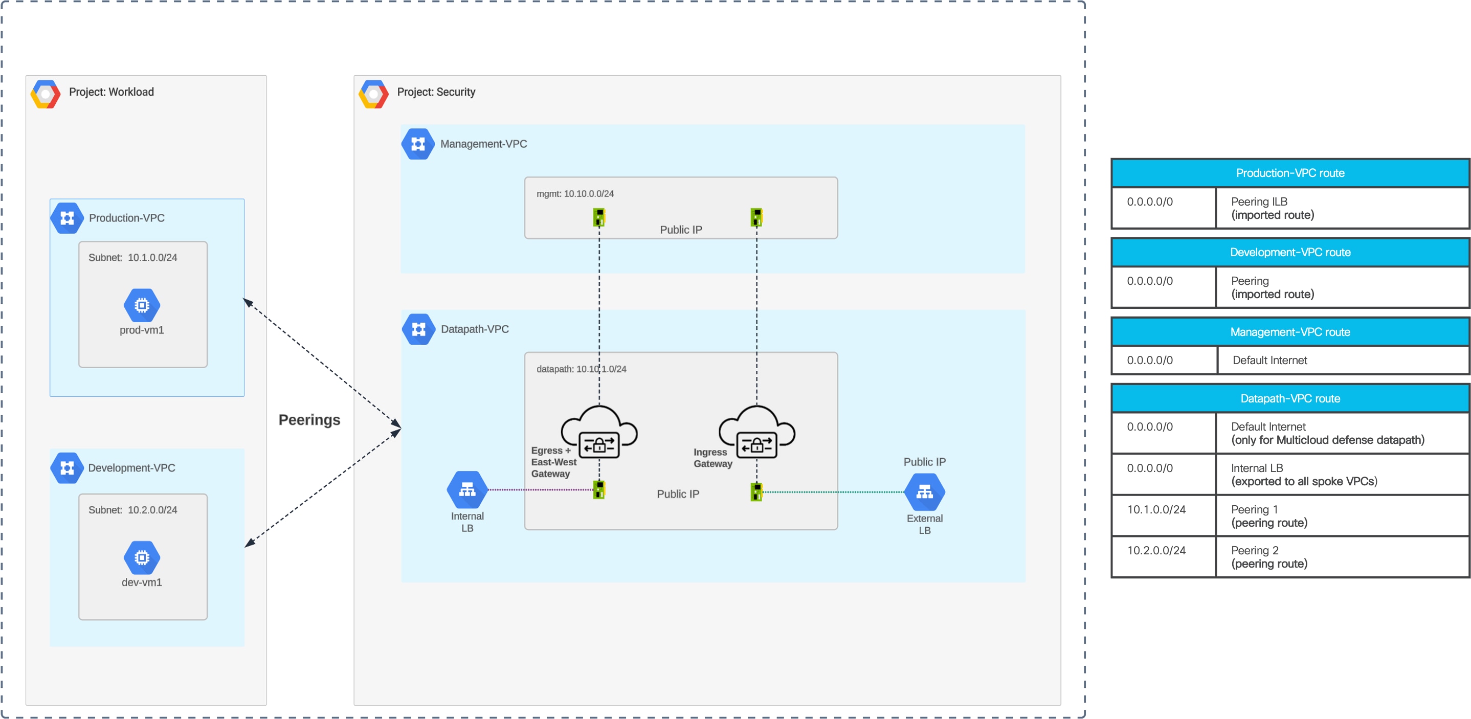
GCP Centralized Ingress – Routing Configuration
Deployment Architecture – GCP Centralized Egress
Refer to Figure 17 for a diagram of GCP Centralized Egress – Deployment Architecture.
Traffic Flow – GCP Centralized Egress
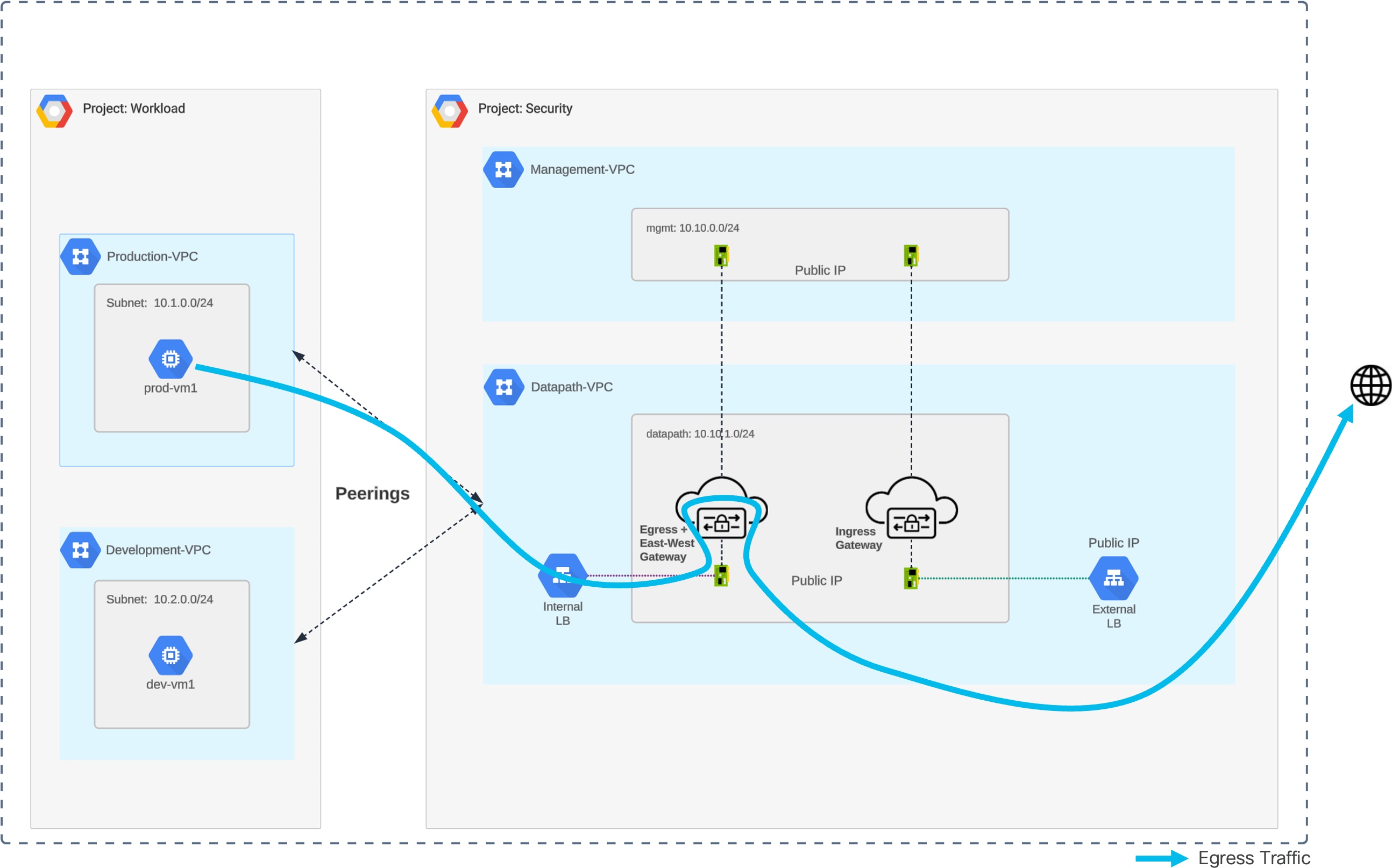
GCP Centralized Egress – Traffic Flow
Routing Configuration – GCP Centralized Egress
Refer to Figure 19 for a diagram of GCP Centralized Egress – Routing Configuration.
Deployment Architecture – GCP Centralized East-West
Refer to Figure 17 for a diagram of GCP Centralized East-West – Deployment Architecture.
Traffic Flow – GCP Centralized East-West
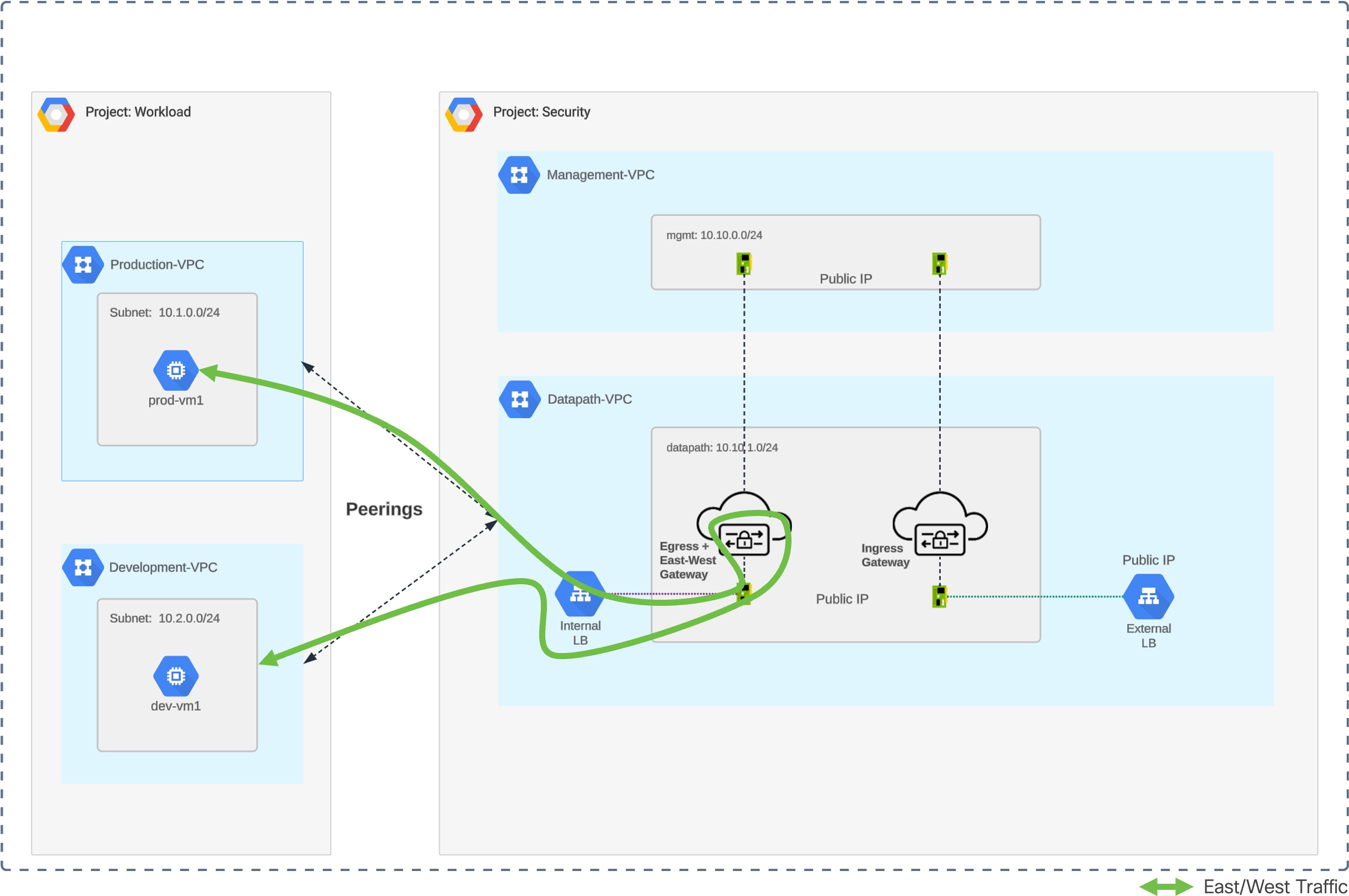
GCP Centralized East-West – Traffic Flow
Routing Configuration – GCP Centralized East-West
Refer to Figure 19 for a diagram of GCP Centralized East-West – Routing Configuration.
If you have feedback on this architecture guide, please send an email to ask-multicloud-defense@cisco.com.
For more information on Cisco Multicloud Defense, see www.cisco.com/go/multicloud-defense.